Woods S30CD User manual
- Type
- User manual

OPER ATOR'S MANUAL
FLAIL
SHREDDER
MAN0943
(Rev. 2/15/2016)
Center Drive
Front & Rear Casters
S20CD
S22CD
S25CD
S27CD
S30CD

2 Introduction
Gen’l (Rev. 3/28/2012)
TO THE DEALER:
Assembly and proper installation of this product is the responsibility of the Woods
®
dealer. Read manual instructions
and safety rules. Make sure all items on the Dealer’s Pre-Delivery and Delivery Check Lists in the Operator’s Manual
are completed before releasing equipment to the owner.
The dealer must complete the online Product Registration form at the Woods Dealer Website which certifies that
all Dealer Check List items have been completed. Dealers can register all Woods product at
dealer.WoodsEquipment.com under Product Registration.
Failure to register the product does not diminish customer’s warranty rights.
TO THE OWNER:
Read this manual before operating your Woods equipment. The information presented will prepare you to do a better
and safer job. Keep this manual handy for ready reference. Require all operators to read this manual carefully and
become acquainted with all adjustment and operating procedures before attempting to operate. Replacement manuals
can be obtained from your dealer. To locate your nearest dealer, check the Dealer Locator at
www.WoodsEquipment.com, or in the United States and Canada call 1-800-319-6637.
The equipment you have purchased has been carefully engineered and manufactured to provide dependable and
satisfactory use. Like all mechanical products, it will require cleaning and upkeep. Lubricate the unit as specified.
Observe all safety information in this manual and safety decals on the equipment.
For service, your authorized Woods dealer has trained mechanics, genuine Woods service parts, and the necessary
tools and equipment to handle all your needs.
Use only genuine Woods service parts. Substitute parts will void the warranty and may not meet standards required for
safe and satisfactory operation. Record the model number and serial number of your equipment in the spaces
provided:
Model:
_______________________________
Date of Purchase:
_____________________
Serial Number:
(see Safety Decal section for location) ____________________________________
Provide this information to your dealer to obtain correct repair parts.
Throughout this manual, the term NOTICE is used to indicate that failure to observe can cause damage to equipment.
The terms CAUTION, WARNING, and DANGER are used in conjunction with the Safety-Alert Symbol (a triangle with
an exclamation mark) to indicate the degree of hazard for items of personal safety.

Introduction 3
MAN0943 (11/1/2013)
TABLE OF CONTENTS
INTRODUCTION . . . . . . . . . . . . . . . . . . . . . . . . . . . . . . . . . . . . . . . . . . . . . . .2
SPECIFICATIONS. . . . . . . . . . . . . . . . . . . . . . . . . . . . . . . . . . . . . . . . . . . . . .4
BALANCE STATEMENT . . . . . . . . . . . . . . . . . . . . . . . . . . . . . . . . . . . . . . . . .5
GENERAL INFORMATION . . . . . . . . . . . . . . . . . . . . . . . . . . . . . . . . . . . . . . .5
SAFETY RULES . . . . . . . . . . . . . . . . . . . . . . . . . . . . . . . . . . . . . . . . . . . . . . .6
SAFETY DECALS . . . . . . . . . . . . . . . . . . . . . . . . . . . . . . . . . . . . . . . . . . . . .10
OPERATOR SIGN-OFF RECORD . . . . . . . . . . . . . . . . . . . . . . . . . . . . . . . .13
OPERATION . . . . . . . . . . . . . . . . . . . . . . . . . . . . . . . . . . . . . . . . . . . . . . . . .14
FIELD OPERATION . . . . . . . . . . . . . . . . . . . . . . . . . . . . . . . . . . . . . . . . . . .19
SHREDDER STORAGE & CLEANING . . . . . . . . . . . . . . . . . . . . . . . . . . . . .22
SERVICE & MAINTENANCE . . . . . . . . . . . . . . . . . . . . . . . . . . . . . . . . . . . .25
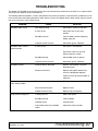
TROUBLESHOOTING . . . . . . . . . . . . . . . . . . . . . . . . . . . . . . . . . . . . . . . . .37
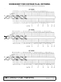
CONTOUR FLAIL PATTERN WORKSHEETS . . . . . . . . . . . . . . . . . . . . . . .38
ASSEMBLY . . . . . . . . . . . . . . . . . . . . . . . . . . . . . . . . . . . . . . . . . . . . . . . . . .40
DEALER CHECK LISTS . . . . . . . . . . . . . . . . . . . . . . . . . . . . . . . . . . . . . . . .47
INDEX TO PARTS LISTS . . . . . . . . . . . . . . . . . . . . . . . . . . . . . . . . . . . . . . .49
BOLT TORQUE CHART . . . . . . . . . . . . . . . . . . . . . . . . . . . . . . . . . . . . . . . .69
BOLT SIZE CHART & ABBREVIATIONS . . . . . . . . . . . . . . . . . . . . . . . . . . .70
INDEX . . . . . . . . . . . . . . . . . . . . . . . . . . . . . . . . . . . . . . . . . . . . . . . . . . . . . .71
PRODUCT WARRANTY . . . . . . . . . . . . . . . . . . . . . . . . . . . . . . . . . . . . . . . .72
REPLACEMENT PARTS WARRANTY . . . . . . . . . . . . INSIDE BACK COVER
Si no lee Ingles, pida ayuda a
alguien que si lo lea para que le
traduzca las medidas de seguridad.
LEA EL INSTRUCTIVO!
!

4 Introduction
MAN0943 (11/1/2013)
SPECIFICATIONS
Maximum Outside Body Width:
20′ . . . . . . . . . . . . . . . . . . 253 in. (6.4 m)
22′ . . . . . . . . . . . . . . . . . . 277 in. (7.0 m)
25′ . . . . . . . . . . . . . . . . . . 309 in. (7.8 m)
27′ . . . . . . . . . . . . . . . . . . 334 in. (8.4 m)
30′ . . . . . . . . . . . . . . . . . . 375 in. (9.5 m)
Cutting Height: . . . . . . . . . . . . . . . . . . . . 3 - 18 in. (7.62 cm to 45.7 cm)
Width of Cut:
20′ . . . . . . . . . . . . . . . . . . 247 in. (6.2 m)
22′ . . . . . . . . . . . . . . . . . . 271 in. (6.8 m)
25′ . . . . . . . . . . . . . . . . . . 303 in. (7.6 m)
27′ . . . . . . . . . . . . . . . . . . 327 in. (8.3 m)
30′ . . . . . . . . . . . . . . . . . . 360 in. (9.1 m)
Knives: Cups
“L” “L” Cut-Off
Number on 20′ . . . . . . . . . . . . 116 . . . . . . . . . . 228. . . . . . . . . . . . 4
Number on 22′ . . . . . . . . . . . . 128. . . . . . . . . . 252. . . . . . . . . . . . 4
Number on 25′ . . . . . . . . . . . . 144. . . . . . . . . . 284. . . . . . . . . . . . 4
Number on 27′ . . . . . . . . . . . . 156. . . . . . . . . . 308. . . . . . . . . . . . 4
Number on 30′ . . . . . . . . . . . . 176. . . . . . . . . . 348. . . . . . . . . . . . 4
Recommended Tire Size: . . . . . . . . . . . . 9.5L - 15,6 ply rated
Tire Inflation Pressure: . . . . . . . . . . . . . . 25 psi
Rotor: Speed . . . . . . . . . . . . . . . . . . . . . 1350 RPM dynamically balanced
Drive: PTO . . . . . . . . . . . . . . . . . . . . . . . 1000 RPM
Weight of Shredder (approximate):
20′ w/4 casters* . . . . 4800 lbs (2177 kg)
22′ w/4 casters* . . . . 5100 lbs (2313 kg)
25′ w/4 casters* . . . . 5600 lbs (2540 kg)
27′ w/4 casters* . . . . 5900 lbs (2676 kg)
30′ w/4 casters* . . . . 7400 lbs (3357 kg)
* each caster assembly weighs
approximately 214 lbs

Introduction 5
MAN0943 (11/1/2013)
IMPORTANT!
BALANCE STATEMENT
Both of the Woods Center Drive Shredder flail tubes
are balanced as rotor assemblies to meet or exceed
factory standards before installation. After installation,
the shredders are statistically inspected to check bal-
ance. These factory efforts allow the shredder to oper-
ate smoothly and be free of excessive vibration when
delivered to the customer.
■
The operator must be familiar with all safety
rules and safety decals before installing and run-
ning the shredder. All personnel must be familiar
with and stay out of the hazard area whenever the
shredder is running. (See Figure 17, page 22).
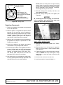
Smooth, acceptable vibration levels can be easily esti-
mated in the field. After machine shutdown and coast
down has been completed, place a quarter on a clean
top panel of the shredder. At full rotor rpm (while main-
taining all safety rules regarding safe distances from
rotating equipment) observe the quarter. If the quarter
stays still and does not bounce around, the operator
can estimate that the shredder is free from excessive
vibration. If the quarter jumps around during full rotor
rpm, the shredder may be operating with excessive
vibration where troubleshooting and maintenance are
required (refer to the Troubleshooting section).
The Woods Center Drive Flail Shredder has been
designed for maximum durability when shredding any
type of crop. While operating in the field, many factors
can affect and degrade shredder rotor balance and
cause increased vibration levels.
●
Operating too low to the ground or in frequent con-
tact with the ground can cause the flail knives to
wear unevenly. This can reduce their chopping
effect and also increase vibration levels.
●
Hitting large rocks or other foreign objects can
damage knives and other rotor parts, causing
excessive vibration.
●
Over time, certain types of soil and crops can also
lead to uneven knife wear and increased vibration
levels.
●
Once field operation has been started, it is the
operator’s responsibility to check and maintain
shredder rotor balance.
●
If knife replacement is required due to wear or
damage, refer to REPLACING FLAILS, page 31.
●
Throughout the life of the flail shredder, removing
the flail tubes for replacement or re-balance may
be necessary.
●
If flail tube replacement is required due to wear or
damage, refer to SERVICING ROTORS (FLAIL
TUBES), page 32.
●
Any re-balance should be done with all knives
installed.
●
Factory balanced repair rotors are available
through your local Woods dealer.
●
Consult with your local balance shop experts or
contact Woods Technical Service for re-balance or
replacement options.
Continued operation with excessive vibration can
cause damage to and shorten component life, void
product warranty, and affect personal safety. Checking
and maintaining shredder rotor balance is the owner/
operator’s responsibility.
GENERAL INFORMATION
The purpose of this manual is to assist you in operating
and maintaining your flail shredder. Read it carefully. It
furnishes information and instructions that will help you
achieve years of dependable performance. These
instructions have been compiled from extensive field
experience and engineering data. Some information
may be general in nature due to unknown and varying
operating conditions. However, through experience
and these instructions, you should be able to develop
procedures suitable to your particular situation.
The illustrations and data used in this manual were cur-
rent at the time of printing but, due to possible inline
production changes, your machine may vary slightly in
detail. We reserve the right to redesign and change the
machines as may be necessary without notification.
Throughout this manual, references are made to right
and left directions. These are determined by standing
behind the equipment facing the direction of forward
travel.

6 Safety
Shredder_S30CD (07/12/2011)
TRAINING
Safety instructions are important! Read all
attachment and power unit manuals; follow all
safety rules and safety decal information. (Replace-
ment manuals and safety decals are available from
your dealer. To locate your nearest dealer, check
the Dealer Locator at www.WoodsEquipment.com,
or in the United States and Canada call 1-800-319-
6637.) Failure to follow instructions or safety rules
can result in serious injury or death.
If you do not understand any part of this manual
and need assistance, see your dealer.
Know your controls and how to stop engine and
attachment quickly in an emergency.
Operators must be instructed in and be capable
of the safe operation of the equipment, its attach-
ments, and all controls. Do not allow anyone to
operate this equipment without proper instruc-
tions.
Keep hands and body away from pressurized
lines. Use paper or cardboard, not hands or other
body parts to check for leaks. Wear safety goggles.
Hydraulic fluid under pressure can easily penetrate
skin and will cause serious injury or death.
Make sure that all operating and service person-
nel know that if hydraulic fluid penetrates skin, it
must be surgically removed as soon as possible by
a doctor familiar with this form of injury or gan-
grene, serious injury, or death will result. CON-
TACT A PHYSICIAN IMMEDIATELY IF FLUID
ENTERS SKIN OR EYES. DO NOT DELAY.
Never allow children or untrained persons to
operate equipment.
PREPARATION
Use a suitable lifting device of sufficient capac-
ity. Use adequate personnel to handle heavy com-
ponents.
Check that all hardware is properly installed.
Always tighten to torque chart specifications
unless instructed otherwise in this manual.
Air in hydraulic systems can cause erratic oper-
ation and allows loads or equipment components
to drop unexpectedly. When connecting equipment
or hoses or performing any hydraulic maintenance,
purge any air in hydraulic system by operating all
hydraulic functions several times. Do this before
putting into service or allowing anyone to
approach the equipment.
Make sure all hydraulic hoses, fittings, and
valves are in good condition and not leaking before
starting power unit or using equipment. Check and
route hoses carefully to prevent damage. Hoses
must not be twisted, bent sharply, kinked, frayed,
pinched, or come into contact with any moving
parts. Operate moveable components through full
operational range to check clearances. Replace
any damaged hoses immediately.
Always wear relatively tight and belted clothing
to avoid getting caught in moving parts. Wear
sturdy, rough-soled work shoes and protective
equipment for eyes, hair, hands, hearing, and head;
and respirator or filter mask where appropriate.
Make sure attachment is properly secured,
adjusted, and in good operating condition.
Make sure spring-activated locking pin or collar
slides freely and is seated firmly in tractor PTO
spline groove.
Before starting power unit, check all equipment
driveline guards for damage. Replace any damaged
guards. Make sure all guards rotate freely on all
drivelines. If guards do not rotate freely on drive-
lines, repair and replace bearings before putting
equipment into service.
Power unit must be equipped with ROPS or
ROPS cab and seat belt. Keep seat belt securely
fastened. Falling off power unit can result in death
from being run over or crushed. Keep foldable
ROPS system in “locked up” position at all times.
Connect PTO driveline directly to power unit
PTO shaft. Never use adapter sleeves or adapter
shafts. Adapters can cause driveline failures due to
incorrect spline or incorrect operating length and
can result in personal injury or death.
Safety is a primary concern in the design and
manufacture of our products. Unfortunately, our
efforts to provide safe equipment can be wiped
out by an operator’s single careless act.
In addition to the design and configuration of
equipment, hazard control and accident preven-
tion are dependent upon the awareness, concern,
judgement, and proper training of personnel
involved in the operation, transport, maintenance
and storage of equipment.
It has been said “The best safety device is an
informed, careful operator.” We ask you to be that
kind of operator.
SAFETY RULES
ATTENTION! BECOME ALERT! YOUR SAFETY IS INVOLVED!

Safety 7
Shredder_S30CD (07/12/2011)
Inspect rubber flaps and swing rod before each
use. Replace if damaged or missing. Flaps must
pivot and hang freely so there are no gaps. Do not
put equipment into service until repaired.
Remove accumulated debris from this equip-
ment, power unit, and engine to avoid fire hazard.
Make sure all safety decals are installed.
Replace if damaged. (See Safety Decals section for
location.)
Make sure shields and guards are properly
installed and in good condition. Replace if dam-
aged.
A minimum 20% of tractor and equipment
weight must be on the tractor front wheels when
attachments are in transport position. Without this
weight, front tractor wheels could raise up result-
ing in loss of steering. The weight may be attained
with front wheel weights, ballast in tires or front
tractor weights. Weigh the tractor and equipment.
Do not estimate.
Inspect and clear area of stones, branches, or
other hard objects that might be thrown, causing
injury or damage.
TRANSPORTATION
Power unit must be equipped with ROPS or
ROPS cab and seat belt. Keep seat belt securely
fastened. Falling off power unit can result in death
from being run over or crushed. Keep foldable
ROPS system in “locked up” position at all times.
Always sit in power unit seat when operating
controls or starting engine. Securely fasten seat
belt, place transmission in neutral, engage brake,
and ensure all other controls are disengaged
before starting power unit engine.
Always raise unit and install transport locks
before transporting. Leak down or failure of
mechanical or hydraulic system can cause equip-
ment to drop.
Always attach safety chain to tractor drawbar
when transporting unit.
OPERATION
Do not allow bystanders in the area when oper-
ating, attaching, removing, assembling, or servic-
ing equipment.
Keep bystanders away from equipment.
Do not operate or transport equipment while
under the influence of alcohol or drugs.
Operate only in daylight or good artificial light.
Keep hands, feet, hair, and clothing away from
equipment while engine is running. Stay clear of all
moving parts.
Always comply with all state and local lighting
and marking requirements.
Never allow riders on power unit or attachment.
Power unit must be equipped with ROPS or
ROPS cab and seat belt. Keep seat belt securely
fastened. Falling off power unit can result in death
from being run over or crushed. Keep foldable
ROPS system in “locked up” position at all times.
Always sit in power unit seat when operating
controls or starting engine. Securely fasten seat
belt, place transmission in neutral, engage brake,
and ensure all other controls are disengaged
before starting power unit engine.
Operate tractor PTO at the rpm speed stated in
“Specifications” section.
(Safety Rules continued on next page)
SAFETY RULES
ATTENTION! BECOME ALERT! YOUR SAFETY IS INVOLVED!

8 Safety
Shredder_S30CD (07/12/2011)
(Safety Rules continued from previous page)
Look down and to the rear and make sure area
is clear before operating in reverse.
Do not operate or transport on steep slopes.
Do not stop, start, or change directions sud-
denly on slopes.
Use extreme care and reduce ground speed on
slopes and rough terrain.
Watch for hidden hazards on the terrain during
operation.
Stop power unit and equipment immediately
upon striking an obstruction. Turn off engine,
remove key, inspect, and repair any damage before
resuming operation.
Leak down or failure of mechanical or hydraulic
system can cause equipment to drop.
MAINTENANCE
Before dismounting power unit or performing
any service or maintenance, follow these steps:
disengage power to equipment, lower the 3-point
hitch and all raised components to the ground,
operate valve levers to release any hydraulic pres-
sure, set parking brake, stop engine, remove key,
and unfasten seat belt.
Before performing any service or maintenance,
lower equipment to ground or block securely, turn
off engine, remove key, and disconnect driveline
from tractor PTO.
Before working underneath, read manual
instructions, securely block up, and check stability.
Secure blocking prevents equipment from drop-
ping due to hydraulic leak down, hydraulic system
failure, or mechanical component failure.
Work not covered in SERVICE & MAINTENANCE
must be done by a qualified dealership. Special
skills, tools, and safety procedures may be
required. Failure to follow these instructions can
result in serious injury or death.
Do not modify or alter or permit anyone else to
modify or alter the equipment or any of its compo-
nents in any way.
Your dealer can supply original equipment
hydraulic accessories and repair parts. Substitute
parts may not meet original equipment specifica-
tions and may be dangerous.
Use a suitable lifting device of sufficient capac-
ity. Use adequate personnel to handle heavy com-
ponents.
Always wear relatively tight and belted clothing
to avoid getting caught in moving parts. Wear
sturdy, rough-soled work shoes and protective
equipment for eyes, hair, hands, hearing, and head;
and respirator or filter mask where appropriate.
Do not allow bystanders in the area when oper-
ating, attaching, removing, assembling, or servic-
ing equipment.
Never go underneath equipment (lowered to the
ground or raised) unless it is properly blocked and
secured. Never place any part of the body under-
neath equipment or between moveable parts even
when the engine has been turned off. Hydraulic
system leak down, hydraulic system failures,
mechanical failures, or movement of control levers
can cause equipment to drop or rotate unexpect-
edly and cause severe injury or death. Follow Oper-
ator's Manual instructions for working underneath
and blocking requirements or have work done by a
qualified dealer.
Make sure attachment is properly secured,
adjusted, and in good operating condition.
Keep all persons away from operator control
area while performing adjustments, service, or
maintenance.
Make certain all movement of equipment com-
ponents has stopped before approaching for ser-
vice.
Air in hydraulic systems can cause erratic oper-
ation and allows loads or equipment components
to drop unexpectedly. When connecting equipment
or hoses or performing any hydraulic maintenance,
purge any air in hydraulic system by operating all
hydraulic functions several times. Do this before
putting into service or allowing anyone to
approach the equipment.
Do not handle knives with bare hands. Careless
or improper handling may result in serious injury.
Your dealer can supply genuine replacement
knives. Substitute knives may not meet original
equipment specifications and may be dangerous.
Tighten all bolts, nuts, and screws to torque
chart specifications. Check that all cotter pins are
installed securely to ensure equipment is in a safe
condition before putting unit into service.
SAFETY RULES
ATTENTION! BECOME ALERT! YOUR SAFETY IS INVOLVED!

Safety 9
Shredder_S30CD (07/12/2011)
Make sure all safety decals are installed.
Replace if damaged. (See Safety Decals section for
location.)
Make sure shields and guards are properly
installed and in good condition. Replace if dam-
aged.
Do not disconnect hydraulic lines until engine is
stopped, power unit is properly secured, equip-
ment and all components are lowered to the
ground, and system pressure is released by oper-
ating all valve control levers.
Leak down or failure of mechanical or hydraulic
system can cause equipment to drop.
STORAGE
Block equipment securely for storage.
Keep children and bystanders away from stor-
age area.
Follow manual instructions for storage.
SAFETY RULES
ATTENTION! BECOME ALERT! YOUR SAFETY IS INVOLVED!

10 Safety
MAN0943 (11/1/2013)
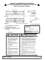
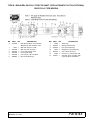
SAFETY & INSTRUCTIONAL DECALS
ATTENTION! BECOME ALERT! YOUR SAFETY IS INVOLVED!
Replace Immediately If Damaged!
3 - SERIAL NUMBER DECAL
CAUTION
PRECAUCION
1. Read Operator's Manual before starting.
2. Stop tractor engine, place all controls in
neutral, lower machine to the ground, set
park brake, remove ignition key, and wait
for all moving parts to stop before
servicing, adjusting, repairing, or
unplugging.
3. Keep all guards and access doors closed
and secured before operating.
4. Keep hands, feet, hair, and clothing away
from moving parts.
5. Do not allow riders.
6. Do not enter rotor area when engine is
running.
7. Never exceed 20 MPH when transporting.
8. Use hazard flashers when transporting.
9. Use drawbar pin with retainer and attach
safety chain.
10. Wear appropriate hearing protection for
prolonged exposure to excessive noise.
11. Review safety information periodically
prior to use.
50030977-B
1. Lea el Manual del Operario antes de empezar.
2. Pare el motor del tractor, ponga todos los controles en
neutro, baje la máquina hasta el suelo, ponga el freno de
estacionamiento, quite la llave del encendido, y espere a
que todas las pizas móviles hayan parado antes de dar
servicio, hacer ajustes, reparaciones, o de desatascar.
3. Mantenga cerrados y asegurados todos los protectores y
las compuertas antes de poner a funcionar la máquina.
4. Mantenga retirados de las piezas móviles, las manos, los
pies, el pelo, y la ropa.
5. No permita que nadie vaya con usted en la máquina.
6. No entre en el área del rotor mientras el motor está en
marcha.
7.
Nunca exceda 32 km/h (20 MPH) al transportar.
8. Use luces intermitentes de aviso cuando viaja con la
máquina.
9. Use el pasador de la barra de tiro con fiador y enganche la
cadena de seguridad.
10. Use un protector apropiado para los oidos cuando esté
expuesto a ruido excesivo por un tiempo prolongado.
11. R
epase la información de seguridad periódicamente
antes del uso.
5 - PN 50030977
1 - YELLOW REFLECTOR PN 20034004
2 - RED REFLECTOR PN 57123
4 - RED-ORANGE FLUORESCENT MATERIAL
PN 20034034

Safety 11
MAN0943 (11/1/2013)
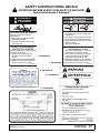
SAFETY & INSTRUCTIONAL DECALS
ATTENTION! BECOME ALERT! YOUR SAFETY IS INVOLVED!
Replace Immediately If Damaged!
(Safety Decals continued on next page)
6 - PN 50030978
ROTATING DRIVELINE HAZARD
To prevent serious injury or death from
rotating driveline:
1. Keep all guards in place when operating.
2. Operate only at 1000 RPM.
3. Keep hands, feet, clothing, and hair away
from moving parts.
PELIGRO CON EL MOVIMIENTO
ROTATIVO DEL EJE MOTRIZ
Para evitar heridas graves o la muerte a causa
de la rotación del eje motriz:
1. Mantenga todos los protectores en su
puesto mientras esté funcionando la
máquina.
2. Hágala funcionar únicamente a 1000 RPM.
3. Mantenga retirados de las piezas móviles,
las manos, los pies, la ropa y el pelo.
50030978-A
DANGER
PELIGRO
DANGER
PELIGRO
ROTATING FLAIL HAZARD
To prevent serious injury or death from
rotating flails:
1. Stop engine, remove ignition key, and wait
for moving parts to stop before servicing.
2. Keep hands and feet away from flails when
engine is running.
3. Keep other people away.
PELIGRO CON LAS CUCHILLAS
CORTADORAS ROTATIVAS
Para evitar heridas graves o la muerte
causadas por las cuchillas rotativas:
1. Pare el motor, quite la llave del encendido
y espere hasta que las piezas móviles
hayan parado antes de dar servicio.
2. Mantenga las manos y los pies retirados de
las cuchillas estando el motor en marcha.
3. No permita que otra gente se acerque.
50030982-A
7 - PN 50030982
10 - PN 50530314
8 - PN 50530138
9 - PN 50530225

12 Safety
MAN0943 (11/1/2013)
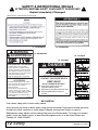
SAFETY & INSTRUCTIONAL DECALS
ATTENTION! BECOME ALERT! YOUR SAFETY IS INVOLVED!
Replace Immediately If Damaged!
14 - PN 50530315
WARNING
HIGH-PRESSURE FLUID HAZARD
To prevent serious injury or death:
1. Relieve pressure on system before
repairing, adjusting, or disconnecting.
2. Wear proper hand and eye protection
when searching for leaks. Use wood or
cardboard instead of hands.
3. Keep all components in good repair.
PELIGRO DE FLUIDO BAJO
ALTA PRESION
Para evitar heridas graves o la muerte:
1. Alivie la presión del sistema antes de
hacer repara ciones, ajustes o
desconecciones.
2. Use protección apropiada en las
manos y en los ojos, cuando revise
para ver si hay fugas. Utilice una tabla
o un cartón en vez de las manos.
3. Mantenga todos los componentes en
buen estado.
50530315-A
ADVERTENCIA
DANGER
ROTATING DRIVELINE
CONTACT CAN CAUSE DEATH
KEEP AWAY!
DO NOT OPERATE WITHOUT -
All driveline guards, tractor and
equipment shields in place
Drivelines securely attached at both ends
Driveline guards that turn freely on
driveline
18864-C
15 - PN 18864
12 - PN 50530728
33347E
16 - PN 33347
(Safety Decals continued from previous page)
BE CAREFUL!
Use a clean, damp cloth to clean safety decals.
Avoid spraying too close to decals when using a pressure washer; high-pressure water can enter
through very small scratches or under edges of decals causing them to peel or come off.
Replacement safety decals can be ordered free from your Woods dealer. To locate your nearest
dealer, check the Dealer Locator at www.WoodsEquipment.com, or in the United States and
Canada call 1-800-319-6637.
11 - PN 50530707

Operator Record 13
MAN0943 (11/1/2013)
OPERATOR SIGN-OFF RECORD
.
Woods Equipment Company follows the general safety
standards specified by the American Society of Agri-
cultural and Biological Engineers (ASABE) and the
Occupational Safety and Health Administration
(OSHA) for agricultural equipment.
Anyone who will be operating and/or maintaining the
flail shredder must read and clearly understand all
Safety, Operating, and Service & Maintenance infor-
mation presented in this manual.
Do not operate or allow anyone else to operate this
equipment until this information has been reviewed.
Review this information annually, before the season
start-up. Make periodic reviews of the Safety and
Operation sections standard practice for those using
any of your equipment.
Use the following Operator Sign-off Record to verify
that each operator has read and understood the infor-
mation in this manual and has been instructed in the
safe operation of the flail shredder.
DATE OPERATOR’S NAME (PRINT) OPERATOR’S SIGNATURE

14 Operation
MAN0943 (11/1/2013)
OPERATION
The Woods Flail Shredder is designed to pick up and
shred crop and plant residue left in the field. Rotational
power to the flails is provided by the tractor PTO.
Be familiar with the flail shredder before starting.
The owner is responsible for training operators in the
safe operation of the flail shredder.
Safety instructions are important! Read all
attachment and power unit manuals; follow all
safety rules and safety decal information. (Replace-
ment manuals and safety decals are available from
your dealer. To locate your nearest dealer, check
the Dealer Locator at www.WoodsEquipment.com,
or in the United States and Canada call 1-800-319-
6637.) Failure to follow instructions or safety rules
can result in serious injury or death.
Never allow children or untrained persons to
operate equipment.
Make sure shields and guards are properly
installed and in good condition. Replace if damaged.
Keep hands, feet, hair, and clothing away from
equipment while engine is running. Stay clear of all
moving parts.
Never allow riders on power unit or attachment.
Before dismounting power unit or performing
any service or maintenance, follow these steps:
disengage power to equipment, lower the 3-point
hitch and all raised components to the ground,
operate valve levers to release any hydraulic pres-
sure, set parking brake, stop engine, remove key,
and unfasten seat belt.
Do not allow bystanders in the area when oper-
ating, attaching, removing, assembling, or servic-
ing equipment.
Keep bystanders away from equipment.
Operate tractor PTO at the rpm speed stated in
“Specifications” section.
Always sit in power unit seat when operating
controls or starting engine. Securely fasten seat
belt, place transmission in neutral, engage brake,
and ensure all other controls are disengaged
before starting power unit engine.
Always comply with all state and local lighting
and marking requirements.
Always wear relatively tight and belted clothing
to avoid getting caught in moving parts. Wear
sturdy, rough-soled work shoes and protective
equipment for eyes, hair, hands, hearing, and head;
and respirator or filter mask where appropriate.
PRINCIPAL COMPONENTS
The Woods Flail Shredder consists of a large rotating
tube with swinging steel flails attached. The flails pick
up or strike crop residue or trash and shred it. Rota-
tional power to the drum is provided by the tractor PTO
through a gearbox in the center of the machine.
For removing the center strip of crop residue, an
optional hydraulically driven blade can be installed
under the cover in the center of the machine.
The flail shredder is designed to be used as a pull-type,
semi-mounted, or 3-point mounted machine.
BREAK-IN OF THE FLAIL SHREDDER
The following should be observed when operating the
unit for the first time:
After operating for 1/2 hour
1. Check all nuts, bolts, and other fasteners. Tighten
to specifications given in the Bolt Torque Chart,
page 68.
2. Tighten wheel bolts to specifications given in the
Bolt Torque Chart, page 68.
3. Check that the flails are in good condition and
swing freely.
4. Check oil level in the gearbox. Add oil if needed.
5. Check that the PTO driveline shield turns freely.
6. Lubricate all grease points.
After operating for 5 to 10 hours
1. Repeat Steps 1 through 5 above.
2. Follow regular service schedule as outlined in
Lubrication Schedule, page 25.
CAUTION
CAUTION

Operation 15
MAN0943 (11/1/2013)
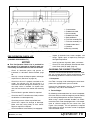
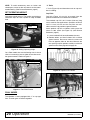
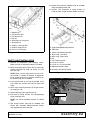
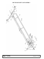
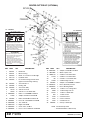
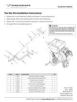
Figure 1. Flail Shredder Principal Components
PRE-OPERATION CHECK LIST
(OWNER'S RESPONSIBILITY)
NOTICE
■
This Pre-Operation Check List is provided for
the operator. It is important to follow for both per-
sonal safety and maintenance of the flail shredder.
___ Check all lubrication points and grease as
instructed in Lubrication Service Record, page
28.
___ Use only a tractor of adequate power and weight
to pull the unit. (See chart on page 16.)
___ Check that the unit is properly attached to the
tractor. On pull-type unit, be sure there is a
mechanical retainer through the drawbar pin and
the safety chain is installed. On 3-point hitch
units, be sure retainers are used on the mounting
pins.
___ Check oil level in gearbox. Add oil as required.
___ Check that the PTO driveline turns freely and that
the driveline can telescope easily.
___ Check tire pressure. Inflate to specified level.
___ Check flails. Inspect for damage or breakage.
Make sure they swing freely on their mount.
Repair or replace as required.
___ Check condition of cutter blade (if so equipped).
___ Inspect all hydraulic lines, hoses, couplers, and
fittings. Tighten, repair, or replace any leaking or
damaged components.
___ Install and secure all guards, doors, and covers.
___ Check PTO clutch operation (See Weasler Auto-
matic Clutch (24K) or (30K), page 34).
CHOOSING THE CORRECT TRACTOR
To ensure safe and reliable operation of the flail shred-
der, use a tractor with the correct specifications. Use
the following guidelines to select the correct tractor.
1. Horsepower
Use Table 1 on page 16 for selecting the tractor horse-
power class appropriate for your unit’s width.
Increase the horsepower level by 25 percent when
operating in hilly, soft, or wet conditions.
2. Tractor Weight
By following recommendations for tractor horsepower,
the tractor will have sufficient weight to provide stability
for unit during field operation or when transporting.
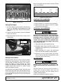
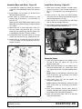
When using a 3-point mounted shredder, we recom-
mend that each tractor be equipped with a full comple-
ment of suitcase weights on the tractor front (see
Figure 2 for example). This will provide the required
front weight for turning and extra traction if equipped
with front wheel assist.
1. Crossmember
2. Rubber belt shield
3. Skid assembly
4. Rubber belt shield
5. Body weldment
6. Flail tube assembly RH
7. Flail tube assembly LH
8. Woods model decal
9. Gearbox
10. Bearing assembly

16 Operation
MAN0943 (11/1/2013)
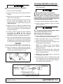
Figure 2. Tractor Front Weight
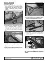
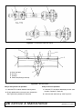
3. 3-Point Hitch
The 3-point hitch models require that the tractor be
equipped with a Category II or Category III 3-point
hitch. If the hitch can be converted from one to the
other, use a Category III to provide a wider stance and
more stability.
Use the upper top link hole for Category III and the
lower hole for Category II as shown in Figure 3.
For easier attachment, use a quick hitch. If not using a
quick hitch, use optional hitch extension.
4. Hydraulic Requirements when Using Center
Cutter Options
The tractor hydraulic system must be capable of 8 gpm
(30 lpm) at 1500 psi (10,335 kPa). The system cannot
exceed 28 gpm or 3000 psi. Either closed-centered or
open-centered systems can be used.
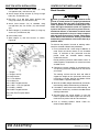
5. Load Sensing Hydraulics (3-Point Models Only)
Many newer tractors are equipped with “load sensing”
hydraulics. The operator is responsible for setting the
tractor hydraulic system to provide “float” on the 3-point
hitch. Refer to the tractor manual for specific instruc-
tions.
The “float” feature will allow the unit to follow the
ground contours during operation. This applies to 3-
point mounted machines only.
6. Drawbar (Pull-Type Models Only)
The tractor drawbar must be set to provide 20” (508
mm), between the end of the PTO shaft and the center
of the drawbar pin for 1-3/4 - 20, 1000 RPM drives. See
Figure 4. This dimension will provide the required
clearance for the CV (Constant Velocity) joint on the
front of the driveline.
NOTE: On Pull-Type models, do not cut driveline.
Figure 3. 3-Point Hitch Attachment
Figure 4. Drawbar Dimension
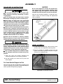
PTO DRIVELINE LENGTH
(3-Point & 2-point Models Only)
■
The unit is equipped with a PTO driveline long
enough to fit any tractor and 3-point linkage sys-
tem.
■
The operator is responsible for measuring the
dimensions of the driveline through its working
range. These dimensions will indicate if the drive-
line requires shorting to operate on the particular
tractor/unit attachment system. The operator must
check dimensions before using the unit for the first
time and each time a different tractor is used with
the unit.
■
Use the following procedure when determin-
ing driveline dimension:
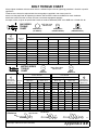
Table 1: Tractor Horsepower (6-8) vs. Unit Width
Width Minimum Horsepower
20′ 120
22′ 132
25′ 150
27′ 162
30′ 180
DP10
Top Link Assembly
Upper Top Link Hole
Lower Top Link Pin
Lower 3-Point Pin
DP11
1000 RPM
16” or 20”

Operation 17
MAN0943 (11/1/2013)
Keep bystanders away from equipment.
1. Clear the area of all bystanders.
2. Attach the 3-point hitch to the unit but not the PTO
driveline.
3. Raise the unit until the tractor PTO and gearbox
shafts are the same height.
4. Measure the dimension between the shaft grooves
on the tractor and implement ends. If this
dimension is less than 34.81 inches, the shaft will
require shortening.
5. Move the unit to its highest and lowest working
position and measure this dimension again. [The
unit’s shaft can telescope (see Figure 6) before it
has been shortened.]
6. If required, shorten the shaft to prevent bottoming
out during use. NOTE: An extra inch of
compression space in the shaft can eliminate
bottoming out during use. Measure to make sure.
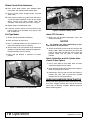
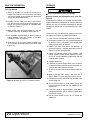
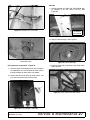
7. Use an abrasive wheel power saw to cut the male
end of the shaft. Cut the same amount from both
the splined shaft and the safety shield. See Figure
5. Use a file to remove any burrs from the cut end.
NOTICE
■
Cut only the male end. Never cut the female end.
8. Never cut more than 9 inches from the male end.
Cutting 1 inch from the male end shortens both the
minimum and maximum lengths by 1 inch.
Figure 5. Cutting the Driveline Shaft
ATTACHING SHREDDER TO TRACTOR
1. Place unit on a level, dry area free of debris and
other foreign object.
Keep bystanders away from equipment.
Connect PTO driveline directly to power unit
PTO shaft. Never use adapter sleeves or adapter
shafts. Adapters can cause driveline failures due to
incorrect spline or incorrect operating length and
can result in personal injury or death.
2. Clear the area of bystanders, especially children.
3. Provide enough clearance to back the tractor
safely into the unit.
■
Do not allow anyone to stand between tractor
and unit when backing up to the unit.
With Quick Hitch Attachment:
4. Set the height of the 3-point hitch so that quick
hitch claws are lower than the mounting pins.
5. Make sure 3-point hitch is set in the non-sway
position. See tractor manual for details.
6. Align the claws under the lower and upper mast
mounting pins while backing up.
NOTE: For a Category II hitch, use the bottom
upper mast hole. For a Category III hitch, use the
top upper mast hole.
7. When the claws are under the pins, slowly raise
the 3-point hitch. Make sure each mounting pin
seats in its respective claw.
8. Release the claw retainer locks to secure the
mounting pins in the claws.
9. Check the top link frame. It should be free to slide
in its mounting slots. This movement allows the
unit to follow the ground contour when cresting a
hill or going through a depression.
Figure 6. Driveline Dimension
CAUTION

18 Operation
MAN0943 (11/1/2013)
Without Quick Hitch Attachment:
10. Back tractor lower 3-point arms between lower
mast plates and align with lower 3-point hole.
11. Place 1-3/4 OD spacer through 3-point arm pivot
(both sides).
12. Push tractor’s 3-point arm to the inside and slide a
1-7/16 OD spacer between to take up the empty
space. Secure with lower 3-point hitch pin
assembly, 1-3/4 OD spacer, and 7/16 x 2 klik pin.
13. Repeat steps 5 and 6 for other side.
14. Lower the tractor’s top link arm and secure in top
hole of upper mast assembly using spacer, hex
bolt, and lock nut.
Pull-Type Model:
1. Check and set the drawbar dimension.
2. Back the tractor up to the hitch.
3. Use a hardened drawbar pin that provides for a
mechanical retainer, such as a Klik pin.
4. Attach safety chain from hammer strap around the
drawbar or cage to prevent unexpected separation.
Provide sufficient slack for turning.
5. make sure the drawbar is pinned in its center
position.
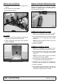
Figure 7. Attaching to Pull-Type Model
Figure 8. Drawbar & Safety Chain
Attach PTO Driveline
1. Make sure the driveline telescopes easily and
shields rotate freely.
NOTICE
■
The drawbar may need repositioning to pro-
vide clearance for the driveline.
2. Attach the driveline to the tractor by retracting the
locking collar. Slide the yoke over the shaft and
push on the yoke until the lock collar clicks into
position. Make sure the yoke is locked into
position.
Attach Hydraulics and Lift Cylinder Hose
(Center Cutter Option)
1. Use a clean cloth to clean hose ends and area
around the couplers on the tractor.
2. Insert the hose male ends into the tractor couplers.
Make sure hoses lock in place.
3. Route hoses along or over the hitch and secure in
position with clips, tape, or plastic ties. Provide
enough slack for turning and lifting.
REMOVING SHREDDER FROM TRACTOR
Reverse the above procedure when removing unit from
the tractor. Engage transport lock channel at the four
struts prior to lowering shredder. Release pressure
before removing hoses.

Operation 19
MAN0943 (11/1/2013)
Figure 9. Transport Lock
FIELD OPERATION
The Woods Flail Shredder is designed with the flexibil-
ity to operate well in almost any kind of crop and terrain
conditions. However, the operator is responsible for
being familiar with all operating and safety procedures
and following them. Each operator should review this
Field Operation section at the start of the season and
as often as required to be familiar with the unit.
Operators should also review the PRE-OPERATION
CHECK LIST, page 15, and Attaching Shredder to
Tractor, page 17.
Safety instructions are important! Read all
attachment and power unit manuals; follow all
safety rules and safety decal information. (Replace-
ment manuals and safety decals are available from
your dealer. To locate your nearest dealer, check
the Dealer Locator at www.WoodsEquipment.com,
or in the United States and Canada call 1-800-319-
6637.) Failure to follow instructions or safety rules
can result in serious injury or death.
Never allow children or untrained persons to
operate equipment.
Make sure shields and guards are properly
installed and in good condition. Replace if damaged.
Keep hands, feet, hair, and clothing away from
equipment while engine is running. Stay clear of all
moving parts.
Before dismounting power unit or performing
any service or maintenance, follow these steps:
disengage power to equipment, lower the 3-point
hitch and all raised components to the ground,
operate valve levers to release any hydraulic pres-
sure, set parking brake, stop engine, remove key,
and unfasten seat belt.
Never allow riders on power unit or attachment.
Do not allow bystanders in the area when oper-
ating, attaching, removing, assembling, or servic-
ing equipment.
Inspect and clear area of stones, branches, or
other hard objects that might be thrown, causing
injury or damage.
Operators must be instructed in and be capable
of the safe operation of the equipment, its attach-
ments, and all controls. Do not allow anyone to
operate this equipment without proper instructions.
Keep bystanders away from equipment.
Operate tractor PTO at the rpm speed stated in
“Specifications” section.
Always sit in power unit seat when operating
controls or starting engine. Securely fasten seat
belt, place transmission in neutral, engage brake,
and ensure all other controls are disengaged
before starting power unit engine.
Always comply with all state and local lighting
and marking requirements.
Always wear relatively tight and belted clothing
to avoid getting caught in moving parts. Wear
sturdy, rough-soled work shoes and protective
equipment for eyes, hair, hands, hearing, and head;
and respirator or filter mask where appropriate.
RUBBER FLAPS OR BELTING
All units are equipped with front shield flaps or belting
along the front of the frame. The shield flaps stop or
deflect trash, stones, or other debris picked up by the
flails.
Be sure the shield flaps or belting are in good condition
for operation. Replace if damaged, torn, or missing.
PREPARING FOR OPERATION
1. Pull into the field and position the unit in a level
area.
2. Lower into operating position.
3. Set the 3-point so the quick hitch is vertical and the
floating upper mast is forward.
4. Use stroke control spacer on four cylinders to set
cutting height.
Flail Height
Set the unit to give a flail height of at least 3 to 6
inches (75 to 150 mm) above the ground. This will
minimize the amount of stones and dirt picked up by
the flails under all operating conditions. (See Balance
Statement, page 5.)
DP101
CAUTION

20 Operation
MAN0943 (11/1/2013)
NOTE: To avoid unnecessary wear on knives and
related parts, never set the unit lower than the recom-
mended setting. (See Balance Statement, page 5.)
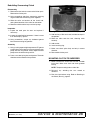
SET OPERATING HEIGHT
Use stroke control spacers. The number and thickness
should be equal on each cylinder to keep shredder
level.
Figure 10. Setting Operating Height
On 3-Point models, be sure the floating mast is free to
slide in its mounting frame to allow the machine to fol-
low ground contours. Refer to Figure 11.
Figure 11. Free-Float Position
FLAIL KNIVES
The shredder is factory equipped with “L” or cup type
flails. The two types are interchangeable.
“L” Flails
“L” flails (Figure 13) work best when trash or crop resi-
due is standing.
Cup Flails
Cup flails (Figure 14) can pick up material from the
ground and work best in matted trash conditions.
The standard cup flail is 8-1/2 inches (216 mm) long
and is used for most applications. Optional 6-3/16 inch
and 7-1/2 inch (157 mm and 191 mm) flails are avail-
able to match the tip position to ground contour.
Attach optional cup flails as follows, making sure that
knives at 180° match (see Figure 12) (see Balance
Statement, page 5):
1. Leave standard flails located between the rows.
2. Remove others and install shorter flails to follow
ground contour. Be sure to mount the same size
flails on opposite sides of the tube. Measure the
row spacing and flail position carefully to minimize
ground contact. See page 38 and page 39.
.
Figure 12. Optional Flail Contour
Figure 13. “L” Flails
Stroke Control
Spacers
DP124
DP12
Floating Top Mast
DP13
Page is loading ...
Page is loading ...
Page is loading ...
Page is loading ...
Page is loading ...
Page is loading ...
Page is loading ...
Page is loading ...
Page is loading ...
Page is loading ...
Page is loading ...
Page is loading ...
Page is loading ...
Page is loading ...
Page is loading ...
Page is loading ...
Page is loading ...
Page is loading ...
Page is loading ...
Page is loading ...
Page is loading ...
Page is loading ...
Page is loading ...
Page is loading ...
Page is loading ...
Page is loading ...
Page is loading ...
Page is loading ...
Page is loading ...
Page is loading ...
Page is loading ...
Page is loading ...
Page is loading ...
Page is loading ...
Page is loading ...
Page is loading ...
Page is loading ...
Page is loading ...
Page is loading ...
Page is loading ...
Page is loading ...
Page is loading ...
Page is loading ...
Page is loading ...
Page is loading ...
Page is loading ...
Page is loading ...
Page is loading ...
Page is loading ...
Page is loading ...
Page is loading ...
Page is loading ...
Page is loading ...
Page is loading ...
-
 1
1
-
 2
2
-
 3
3
-
 4
4
-
 5
5
-
 6
6
-
 7
7
-
 8
8
-
 9
9
-
 10
10
-
 11
11
-
 12
12
-
 13
13
-
 14
14
-
 15
15
-
 16
16
-
 17
17
-
 18
18
-
 19
19
-
 20
20
-
 21
21
-
 22
22
-
 23
23
-
 24
24
-
 25
25
-
 26
26
-
 27
27
-
 28
28
-
 29
29
-
 30
30
-
 31
31
-
 32
32
-
 33
33
-
 34
34
-
 35
35
-
 36
36
-
 37
37
-
 38
38
-
 39
39
-
 40
40
-
 41
41
-
 42
42
-
 43
43
-
 44
44
-
 45
45
-
 46
46
-
 47
47
-
 48
48
-
 49
49
-
 50
50
-
 51
51
-
 52
52
-
 53
53
-
 54
54
-
 55
55
-
 56
56
-
 57
57
-
 58
58
-
 59
59
-
 60
60
-
 61
61
-
 62
62
-
 63
63
-
 64
64
-
 65
65
-
 66
66
-
 67
67
-
 68
68
-
 69
69
-
 70
70
-
 71
71
-
 72
72
-
 73
73
-
 74
74


Woods S30CD User manual
- Type
- User manual
Ask a question and I''ll find the answer in the document
Finding information in a document is now easier with AI
Related papers
Other documents
-
Snapper 1685203 User manual
-
Woods Equipment S30CD User manual
-
Greenlee Caster Installation - Job Box Manual User manual
-
-
Dodge H-Box Torque-Arm Assembly Assembly Instructions
-
Metrologic MS 1690 Focus Series Stand Installation Manual
-
 Land Pride FM2072 Series User manual
-
 Kellfri 35-SKL145 User manual
-
 EarthQuake 1692327 User manual
-
Danfoss S90 P Installation guide


