Page is loading ...

MODEL 44 CE/RPW
JUNE 1985
SINGLE TANK RACK CONVEYOR
DISHWASHERS
SERVICE MANUAL
INCLUDES:
-Warranty Policy -Sequence of Operation
-Installation Requirements -Basic Functions of Dishwasher
-Operating Instructions -Maintenance and Care
-Table Dimensions -Illustrated Parts List
-Wiring Diagrams -What's Not Covered by Warranty
-Troubleshooting Guide
WORLD HEADQUARTERS & MANUFACTURING OPERATIONS
Highway 25E, P.O. Box 1060
Barbourville, KY
40906
888/800-JMSC
FAX 606/523-9196
November 6,1998 P/N 7610-100-21-00 Rev A

INDEX
WARRANTY INSIDE FRONT COVER
SPECIFICATIONS
3
GENERAL INSTRUCTIONS (Installation) 4
GENERAL INSTRUCTIONS (Operation)
6
GENERAL INSTRUCTIONS (Preventive Maintenance) 7
LOWER WASH HEAD ASSEMBLY 8
UPPER WASH ASSEMBLY 8
FINAL RINSE ASSEMBLY 8
REPLACEMENT of SWITCHES in CONTROL PAN EL
9
THERMOSTAT ADJUSTMENT.
10
SERVICE INSTRUCTIONS (lncoming Water Solenoid Valve) 11
REPLACING SEAL and CERAMIC on WASH PUMPS
12
WASH PUMP ASSEMBLY 13
TROUBLESHOOTING GUIDE
14
TORQUE-TAMER 22
PAWL BAR ASSEMBLY 26
CONVEYOR DRIVE ASSEMBLY and MOTOR
27
CAM and CLUTCH ASSEMBLY 28
LOAD SENSOR SWITCH CONVERSION 29
CONVEYOR DRIVE ASSEMBLY 31
LOAD SENSOR SWITCH DETAILS 32
LOAD SENSOR HOLE LOCATION
32
WIRING of LOAD SENSOR SWITCH CIRCUIT
33
ELECTRICAL DRAWINGS 34
PARTS LIST 38
PARTS DISTRIBUTORS INSIDE BACK COVER

SPECIFICATIONS
OPERATING CAPACITY
Racks per hour (NSF Rated) 198
Dishes per hour 5000
Glasses per hour 5000
CONVEYOR SPEED
Feet per minute 5.5
WASH TANK CAPACITY
Gallons 24
WASH PUMP CAPACITY
Gallons per minute 240
THERMOMETER
Wash-°F 140-160
Rinse-°F 180-195
WATER REQUIREMENTS (NSF Rated)
Inlet Temperature °F 180
Gallons per hour 414
Flow pressure PSI 20
Flow GPM 6.9
Inlet-lPS 3/4"
Drain-IPS 1-1/2"
WASH PUMP MOTOR
Horsepower 1
CONVEYOR MOTOR
Horsepower 1/16
ELECTRIC HEAT WASH
KW 13
DIMENSIONS
Length (table to table) 44"
Width 25"
Height 55"
Standard table height ± 1/2" 34"
Maximum height for dishes 16"
STANDARD RACKS
Dish 19-3/4x19-3/4 4
Combination 2
SHIPPING WEIGHT BASIC MODELS
(approx.) 600
ELECTRICAL RATING
Volts: 208/220
Phase:1/3
Amps: (approx.)
Specifications subject to change without notice.

GENERAL INSTRUCTIONS
(INSTALLATION/DIMENSIONS) for 44CE SERIES
Note: Read the following instructions carefully. Proper installation of your
Jackson Dishwasher will assure proper machine operation.
1. Open the front door (hook open) and remove dish, cup, and glass racks, and set to one side for later use.
Remove the tape holding the overflow strainer, the pump intake strainer, and the wash head assembly
that are inside the machine.
2. Cut straps holding machine to base of crate, ease machine on to floor and slide into place of
installation.
3. Connect drain to bottom of machine (1 1/2" IPS female fitting on bottom of wash sump) with proper slope
to conform with local and/or national codes. Drain is a gravity feed system from machine.
4. Connect incoming 3/4" water line with capacity to supply 6.9 gallons per minute flow, at 20 PSI at a
temperature of 180°F+. This connection is just before the Y-strainer. Connect to conform with local
and/or national codes (STANDARDS).
5. Electrical connections should be made through hole in back of control box to terminal board inside (to the
left lower side of control box). This terminal board is accessible by removing the lower cover plate. The
terminals are marked L1, L2 (requiring 208—230V, single phase), or L1, L2, L3 (requiring 208—230V,
three phase). There is a grounding lug inside of the control box on the bottom left. Be sure all
connections made are tightened properly. Refer to data plate for Voltage and Amperage totals.
6. Install the proper circuit breaker, wire, and conduit size to conform with local and/or national codes. Refer
to data plate for electrical loads.
7. DO NOT APPLY POWER UNTIL STEP 10.
8. Insert pump intake strainer, overflow strainer, runoff sheets, and lower wash manifold, then close door.
9. Turn on hand valve controlling water supply to machine; check for any leaks in plumbing and
connections.
10. To energize electrically, proceed as follows:
a. Turn on customer's circuit breaker controlling machine.
b. Check voltage at incoming terminal L1, L2, and L3 (if applicable). It should match data
plate voltage. Voltage at L1 and L2 should be checked to ground individually to ensure
that a high (or wild) leg is not connected to L1 or L2. (Voltage exceeding 150V to
ground would indicate high leg.)
c. If voltages are in required range, turn on 15 amp circuit breaker. The 15 amp circuit
breaker protects and controls the motors and control circuit only; it is not meant to protect or control
the wash heaters.
d. Insert a rack into the machine, be sure the curtains are in place.
e. Turn the fill handle on the front of the machine to supply the unit with water. It should
take less than four minutes to fill the wash tank. When the desired level is reached turn
the handle back to the original position.
f. Open the front door and check the water level. It should be 1/4" below overflow level. If
not, check the incoming water line making sure that the valve fully opens and closes as
the handle is turned on and off.
g. If the water is the proper level, close the front door and turn on the heat switch. The
heaters are in the wash tank and are utilized to maintain the wash water temperature at
150°.
h. Turn on the conveyor switch. This will set the conveyor pawl bar into motion to pull the
rack of ware through the unit.
i. The unit is now ready to proceed with the washing of dishes in accordance with the
operating instructions in this manual, and the instruction sticker on the front door of
the dishwasher.
Note: As the racks leave the unit do not allow them to accumulate more than three in a row.


GENERAL INSTRUCTIONS
(OPERATION) 44CE
Note: Read instructions carefully. Proper operation of your Jackson Dishwasher will assure
clean and sanitized glasses and dishes at optimum efficiency.
Dish Preparation
1. Scrape the dishes thoroughly.
2. Pre-rinse the dishes by soaking or by spraying off with a pre-rinse hose.
3. Place the dishes and cups in the dish rack with cups upside down.
4. Place the glasses and silverware in the combination glass-silverware rack with the
glasses upside down. Scatter the silverware loosely on the bottom of the rack. Do not put glasses on top
of the silverware.
NOTE: When silverware is in an upright position, it washes and rinses better than lying flat. These
compartment silverware racks are available through your dealer or service agency.
Machine Operation
1. Open the front door and insert the pump intake strainer, overflow strainer, runoff sheets, and lower wash
manifold.
2. Close the door.
3. Turn the fill valve handle on the front of the unit- It should take less than four minutes for the water level
to reach the top of the overflow. When the desired level is reached turn the handle back to the original
position.
4. Turn on the heat switch, letting the wash temperature reach 150°.
5. Slide in a rack of dirty dishes.
6. Add detergent* (see Detergent Recommendation). If an automatic detergent dispenser is used, follow
the manufacturer's instructions.
7. Start the wash cycle of the dishwasher by flipping the start switch in a up position.
8. To set the conveyor pawl bar assembly in motion flip the conveyor switch in the up position. The pawl
bar assembly automatically pulls the rack through the machine once it enters the opening.
9. When the rack leaves the other end of the machine it should be removed or not allowed to accumulate
more than three racks on the table. This will prevent the clutch from burning out.
10. Once the wash cycle is activated there is no need to turn it off until the end of the meal period. Repeat
steps 6, 8, and 9 for each rack of ware.
11. At the end of a meal period or the end of the day, shut off the heater, wash, and conveyor switch. Drain
the machine by removing the overflow strainer. Clean both strainers, the overflow and the inside
strainer, of all foreign debris and build-up and flush out the unit.
* Detergent Recommendation and Rinse Additives:
We suggest you contact your local detergent specialists for the correct detergent and rinse additives for the
area. To help until one can be reached, we suggest that you use a non-foaming dishwasher detergent,
approximately one-quarter cup in wash tank, when machine is filled the first time, then one level tablespoon
each cycle (or load) thereafter. This may have to be increased or decreased to obtain satisfactory results.
6

GENERAL INSTRUCTIONS
(PREVENTIVE MAINTENANCE)
(THE FOLLOWING IS TO BE PREFORMED AS NEEDED.)
Note: Read carefully. Proper maintenance of your Jackson Dishwasher will ensure optimum
service with a minimum of down time.
1. To remove all lime and corrosion deposits.
a. Fill the machine with wash water as would ordinarily be done for washing.
b. Open door and place one cup or more of de-liming compound into the water. (Be sure
to follow manufacturer's directions if they vary from these being given) which is
available from your detergent supplier.
c. Turn on wash switch and allow to wash for five minutes.
d. Open door-and examine the interior. All lime should be removed and parts should be
shiny. If not, allow to wash for longer period-
e. After the interior is clean, empty the wash water by removing overflow strainer.
f. Replace overflow strainer. Refill machine and allow to run for two minutes, then, again
drain the wash reservoir.
g. Refill as it is ready for regular operation.
2. Clean strainers.
a. Clean around overflow and pump intake strainer holes.
b. Clean around pump intake (toothbrush makes excellent tool for cleaning).
3. Clean Y-strainer on incoming water line. (Water to machine must be turned off for this operation).
a. Remove plug and clean strainer.
4. Clean rinse tubes.
a. Remove end plugs on lower and upper rinse.
b. Clean all rinse tubes with special brush supplied.
c. If spray holes in the rinse tubes are clogged, they may be cleaned with a pointed tool.
5. Clean wash head assembly.
a. If spray jets are plugged, use pointed tool to dislodge and flush with water.
b. If lodged items still remain in wash tubes, remove wash assembly by first removing
rinse assembly.
c. Clean assembly at sink by flushing water through spray jets. d. Reinstall wash and rinse
assemblies. (See page with instructions).
6. Clean any deposits which may have built up on exterior moving parts.
7

UPPER WASH ASSEMBLY
P/N 1990
ITEM P/N DESCRIPTION
1. 2035 WASH HEAD TUBE CAP
2. 2020 WASH HEAD TUBE
3. 2025 WASH HEAD SPRING CUP
4. 2030 WASH HEAD SCREWS
0203700 TUBE CAP W/"O" RING
FINAL RINSE ASSEMBLY
P/N 6137500
ITEM PIN DESCRIPTION
5. 1390 RINSE ASSEMBLY UPPER NOZZLES
6. 1395 RINSE ASSEMBLY LOWER NOZZLES
7. 1400 RINSE ASSEMBLY END PLUGS
8

REPLACEMENT of SWITCHES In
CONTROL PANEL
There are three switches installed in the control box cover panel. These are the conveyor, wash, and
heater switches.
Before working on machine, it is important that power be turned off at customer's circuit breaker to prevent
the possibility of electrical shock, trip breaker to "off" position. Then turn machine breaker "on" located right
side of control box.
Remove the control panel from the control box. The three switches are mounted in individual round holes
with a keyway. By using a pair of pliers or open end wrench, it is possible to loosen the inside nut enough
to allow the outside nut holding the switch to be removed by fingers. Push switch out of hole.
If a switch is found to be defective, replacement can be achieved by placing the new switch next to the old
one. To make sure the new switch is not upside down, line up with the keyways. Transfer wires one at a
time to the new switch. If this is not practical, pull wires off, one at a time and tag them for proper
replacement.
Put switches back into panel, make sure switch protrudes through panel properly, tighten both nuts, and
replace control panel on control box. Power can now be applied to dishwasher and run through cycles
checking all operations.
P/N 1575
1. CONNECTION TERMINALS
2. INSIDE NUT
3. PANEL PLATE
4. OUTSIDE NUT
5. BAT OR TOGGLE HANDLE
9

THERMOSTAT ADJUSTMENT
The thermostat can be adjusted by turning screw #1 (see picture) on the thermostat control box cover.
(Remember the present setting, in case the problems are elsewhere in the control circuit). A CW rotation
is used to obtain a lower temperature setting and a CCW rotation is used to obtain a higher temperature
setting. A 1/8 turn of screw #1 changes the temperature approximately 15°F. If screw #1 is turned all the
way to its stop in either direction; adjust screw #2 as follows. DO NOT TOUCH THE SCREW SEALED
WITH RED PAINT. When adjusting screw #2 power should be disconnected during adjustment.
Set screw #1 so that it can be turned-equal distances in either direction, then:
— if screw #1 stopped while turning in CW direction, turn screw #2 in CW direction slowly and only
1/8 of a turn or less per complete cycle of the unit.
— if screw #1 stopped while turning in CCW direction, turn screw #2 in CCW direction slowly and
only 1/8 of a turn or less per complete cycle of the unit.
Three-fourths of a turn will bring the thermostat to approximately the same setting obtained where
screw #1 stopped. Check the present temperature setting before attempting any further adjustments.
Use screw #1 for any further adjustments.
NOTE: Making large moves in adjusting may cause misalignment thus increasing
the chances that further adjustment cannot be made and the thermostat
will have to be replaced.
10

SERVICE INSTRUCTIONS
(INCOMING WATER SOLENOID VALVE)
To Take The Valve Apart
Disassembly - These valves may be taken apart by unscrewing the
bonnet and the enclosing tube assembly from the valve body assembly.
See Fig. 3. After unscrewing, carefully lift off the bonnet and enclosing
tube assembly. Don't drop the plunger. The "0" ring seal and diaphragm
cartridge can now be lifted out.
Be careful not to damage the machined faces while the valve is apart.
To Reassemble - Place the diaphragm cartridge in the body with the
pilot port extension UP. Hold the plunger with synthetic seat against the
pilot port. Make sure the "0" ring is in place, then lower the bonnet and
enclosing tube assembly over the plunger. Screw bonnet assembly
snugly down on the body assembly.
Possible Problems
Pilot Port extension #1 clogged
Hole #2 clogged
Remedy
Pass heated straight pin through hole #2 or
clean hole #1
11

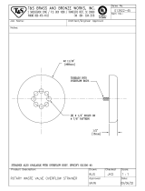
REPLACING SEAL and CERAMIC
on WASH PUMPS
Function:
The pump is part of the total motor-pump system and utilizes one shaft seal and ceramic to prevent the
pump from leaking around the impeller and shaft. One gasket is used to prevent leakage between the
pump mounting plate and the machine pump plate.
Replacement of Seal and/or Ceramic:
1. Remove the power source to the machine by turning the circuit breaker to its "off" position on the side of
the control box.
2. Drain the machine by removing the overflow strainer in the wash tank.
3. Support the motor—remove the four nuts holding the pump/motor to the machine's pump plate.
4. Carefully pull motor outward, move from side to side as required to remove from machine.
5. Set motor and pump on a sturdy stand close to machine or remove wires and conduit to allow
motor/pump to be moved to a better work station.
6. Insert a firm object into the blades of the fan and use 1 5/16" ratchet to remove bolt holding impeller.
After the bolt is removed, pull the impeller up and off of the shaft.
7. The ceramic is imbedded in the pump mounting plate and usually does not need
replacement, but the seal normally would when water leaks around the motor shaft area.
If replacement of either is required, proceed as follows:
a. Remove the four bolts holding the pump mounting plate to the motor.
b. Slide the mounting plate up and off of the shaft and motor. The imbedded ceramic and shaft seal will
be removed with the mounting plate.
c. Turn over the plate and push the seal and/or ceramic out of the housing carefully. It may be
necessary to break the ceramic to remove it.
d. Clean the hole where the ceramic was installed.
e. Lightly coat with a lubricant around the new ceramic's edges and "0" ring. Gently press the ceramic
into place against the snap ring in the housing. Make sure that the grooved side of the ceramic faces
the motor and housing snap ring, leaving the smooth side toward the impeller.
f. Make sure that the woodruff key is in place in the shaft and then set the plate back
on the motor over the shaft.
Note: A field tool can be made (to ease installation of seal) from a pipe or tube (3/4" CPVC
typical example) that has proper outside and inside dimensions. It must fit over step
down in shaft, but be close to larger shaft size on outside- To accommodate woodruff,
cut long slot in tube. Lubricate tube slip seal over tube onto shaft.
g. Lightly coat with a lubricant the new seal face and gently press it into place over the shaft with seal
face against the ceramic. SEE NOTE ABOVE.
h. Place the spring over the shaft with the metal cap up. Press the impeller down onto the shaft, aligning
the keyway of the impeller with the woodruff key.
i. Tighten the impeller washer, lockwasher, and bolt into place. Replace the four bolts that hold the
mounting plate to the motor.
8. Reinstall the pump and motor in the unit by reversing steps one through eight (it is suggested that a new
pump gasket be installed).
Impeller Rotation:
When facing the impeller after mounting it on the motor shaft, the impeller should turn in a CCW
direction.
12

ITEM P/N DESCRIPTION
1. 1027 PUMP MOTOR
2. 1065 WOODRUFF KEY
3.
WASHER, RUBBER
4. 1080 SNAP RING
5. 1050 CERAMIC FACE W/"O" RING
6. 1045 PUMP MOUNTING PLATE
7. 1050 SEAL FACE
8.
PLATE TO MOTOR MOUNTING BOLTS &
LOCKWASHERS
9. 1050
SEAL ASSEMBLY (SEAL SPRING & CUP
WASHER)
10. 1055 PUMP IMPELLER
11. 1075 IMPELLER WASHER
12. 1070 IMPELLER BOLT & LOCKWASHER
13. 1060 PUMP MOUNTING GASKET
13

TROUBLE SHOOTING GUIDE
The information contained herein is intended to help you solve some problems that may exist on your dishwasher from time to time.
Anything not covered in this guide should be referred to the factory. References to section drawings within this book will be made
throughout this "Trouble Shooting Guide." Refer to these section drawings to help you in correcting the problems.
PROBLEM CAUSE SOLUTION
Temperature readings not within required
range.
1. Thermometer is defective.
1. Check thermometer by using a
thermometer known to be accurate. If
defective, replace.
2. Heat switch contactor, elements, thermostats,or
low-water level control.
2. Refer to bottom drawing and electrical
drawing.
Final Rinse switch
1. Refer to incoming water and rinse section for
solution.
Washing action does not get dishes
clean.
1.
Spray tubes clogged with paper towels, toothpicks,
etc.
1. Remove upper spray tubes and clean,
remove lower assembly and clean
spray tubes by removing tube caps.
2. Pump intake strainer clogged.
2. Remove pump intake strainer and
clean.
3. Scrap basket full; will not allow water to return to
tank.
3. Remove scrap basket and clean.
4. Overflow and drain tube not solid in drain fitting,
not allowing pump sufficient water, for pumping
action.
4. Remove overflow and drain tube and
replace solidly in drain fitting.
5- Pump clogged.
5. With pump intake strainer off, check. If
any obstructions in the pump intake hole,
remove.
6. Pump impeller not turning; therefore, motor is not
turning and pumping.
6. Refer to Pump/Motor Section.
Water in wash tank
excessively high.
1. Overflow and drain tube clogged or covered with
napkin, etc.
1. Drain tank and refill to ensure clean
water.
Pawl bar not operating to push dishes
through dishwasher.
1. Something jammed between pawl bar and clean
dish side of dishwasher.
2. With pawl bar removed, drive rod doesn't
operate.
1. Remove obstruction.
2. Check section "Conveyor Drive
and Motor."
Unable to maintain heat in wash tank.
1. Water too low in wash tank and does not touch
probe.
1.Turn fill valve on refill machine (make
sure overflow and drain tube are
securely in drain).
2. Low-water cutoff system not operating. (Probe is
part of this system.)
2. Refer to "Electrical Section Drawing."
Read Electrical Checkout.
14

TROUBLE SHOOTING GUIDE
PROBLEM CAUSE SOLUTION
3. Thermostat not functioning properly. 3. Follow 6A.
4. Heaters not functioning. 4. Follow 6A.
Vacuum breaker is allowing water to
escape and spray on top of machine
and against wall.
1. Vacuum breaker is defective.
1. Remove top of vacuum breaker by
unscrewing. Lift poppet out and clean.
2. Gasket on poppet split or worn.
2. Replace rubber gasket and washer on
poppet completely.
Rinse temperature not within required
range.
1. See "Top Section" for correction action.
Little or no water coming from final
rinse nozzles when machine is in
operation.
1. 3/4" solenoid valve not opening to allow flow of
water.
1. Dismantle, clean and check out
solenoid valve according to instructions
on solenoid sheet Replace solenoid if
necessary.
2. Final rinse limit switch faulty.
2. Check switch to see that it has
continuity when in "on" position, if not
replace.
3.
Rinse trip assembly is not tripping final rinse limit
switch.
3. Make sure that coupling between
vertical rod from final rinse paddle is
tight and turns final rinse limit switch, if
not tighten. If vertical rod is bent,
straighten.
4. Water on incoming plumbing supplied by
customer not sufficient.
4. Check flow of water. If water isn't
sufficient, check line coming to
dishwasher and make sure there are no
obstructions and no extreme number of
branches off from this line that could
steal water.
5. Rinse nozzles clogged.
5. Unscrew rinse nozzles and clean. With
nozzles out, activate machine to see if
good amount of water flows. If not,
check plumbing.
Can't fill machine. 1. Water to machine not turned on. 1.Tum water supply on.
15

TROUBLE SHOOTING GUIDE
PROBLEM CAUSE SOLUTION
Wash tank runs out of water. (This is
covered on previous page and is
continuation.)
1. 1/4" Solenoid valve not operating.
1. Check Solenoid valve to see that it is
operating, if it doesn't operate, replace.
2. Final rinse limit switch is defective.
2. Check final rinse limit switch out to see
if it has continuity across the normally
closed contacts. If not, replace switch.
Final rinse catch basin overflowing. 1. Crumb cup in drain clogged. 1. Remove crumb cup and clean.
Water level too high or low in wash
tank.
1. Check previous Section for solution.
2. "O" ring not in drain fitting or damaged.
2. Check to see that there is an "0"
ring in
the drain fitting and it is not damaged.
Replace if necessary.
Pawl bar moves with no load but does
not move when loaded.
1. Clutch slipping.
1. Adjust clutch. (See page insert for
instructions of Torque Tamer).
Pump/motor doesn't run. 1. Wash motor switch is defective.
1. With switch on, check to see that you'
re
getting power into the switch and out of
the switch, check back to circuit
breaker on dishwasher. If you are, but
not out of the switch, replace switch.
2. Loose wires or connections.
2. Check all wiring to and from motor to
see that there are no loo
se connections
or broken or frayed wires. Repair or
replace as necessary.
3. Pump jammed.
3. See previous instructions "Bottom
Section."
Conveyor motor doesn't operate. 1. Conveyor push button switch is defective.
1. Check to see that power is going into
the switch for the conveyor and is
coming out the other side or turn off
power and check the continui ty by
pushing switch in and out to see that it
does turn the system on and off. If
switch's defective, replace.
16

TROUBLE SHOOTING GUIDE
PROBLEM CAUSE SOLUTION
2. Loose wires or connection.
2. Check all wiring for breaks, loose
terminals and connections, and repair
accordingly.
3. Motor is defective.
3. Motor hums or doesn't operate at all.
Defective, replace motor.
Heat circuit does not operate (wash
tank not at required temperature).
1. Water level in wash tank below low-water cutoff
probe.
1.FiII wash tank to overflow level.
2.Thermostat is out of adjustment or defective.
2. By turning adjustment screw, adjust
thermostat up or down as needed. If this
doesn't increase or decrease the heat,
with a small piece of in
sulated wire, short
the two terminals on the thermostat out
with the heat switch on. This will by-
pass
the thermostat action and if the water
temperature rises, the thermostat is
defective and should be replaced.
3. Water level control is defective.
3. With heat switch on, check to see that
the terminals L1 and L2 on the water-
level control have power coming to them,
then with a short link of insulated wire.
Jump terminals 'L' and 'H'. These
terminals are on the low voltage (24V)
system.
If low water control is operating, the contacts
in the little plastic-coated relay will work or
move. (Before attempting above, remove a
wire to Water-level probe).
4. Water-level control checked out okay on 9C, but
heat circuit still does not operate.
4. Make sure that the probe wire has been
replaced.
17

Item No.
P/N DESCRIPTION
1. 453 CURTAIN
2.
1691 WASH THERMOMETER
3.
1377A
RINSE ACTUATOR HELPER SPRING
4.
1378 RINSE ACTUATOR COUPLING
5.
1377B
RINSE LIMIT SWITCH BRACKET
6. 1635
1636 RINSE LIMIT SWITCH
ITEM P/N DESCRIPTION
7. 1692
RINSE THERMOMETER
8. 526 DOOR FRONT CATCH
9. 1379
RINSE ACTUATOR ROD BRACKET
10. 1376
RINSE ACTUATOR PADDLE & ROD
11. 844 PROBE COVER
12. 525 FRONT DOOR
13. 530 FRONT DOOR HANDLE
18

ITEM P/N DESCRIPTION
1. 1700 THERMOSTAT
2. 605 WASH TANK HEATER (6 EA.)
3. 843 LOW WATER PROBE
4. 1805 BACK CONVEYOR TRACK
5. 1410 LARGE RUNOFF SHEET
6. 1405 SMALL RUNOFF SHEET
7. 425 CONVEYOR PAWL BAR ASSEMBLY
8- 2035 WASH HEAD TUBE CAP
9. 2020 WASH HEAD SPRAY TUBE
ITEM
P/N DESCRIPTION
10. 2025 WASH HEAD SPRING LOCK
11.
TRANSFER SHEET
12. 2040 WASH HEAD MANIFOLD COVER
13. 1530 LARGE OVERFLOW TUBE
14. 1525 PUMP INTAKE STRAINER
15. 1535 TRACK & SCRAP STRAINER ASS'Y
16. 1790A
FRONT TRACK LARGE SECTION
17. 1790B
FRONT TRACK SMALL SECTION
19

ITEM
P/N
DESCRIPTION
1. 1414 DRAIN CRUMB CUP
2. 1530 OVERFLOW TUBE
3. 540 DRAIN "O" RING
ITEM P/N DESCRIPTION
4. 0002826 WASH DRAIN FITTING
5.
DRAIN OUTLET 1 1/2" IPS
21
/