Page is loading ...

MODEL 150 B/PRB
HIGH TEMPERATURE DOOR
TYPE DISHWASHER
1983-1989
SERVICE MANUAL
INCLUDES:
-Warranty Policy -Basic Functions of Dishwasher
-Installation Requirements -Maintenance and Care
-Operating Instructions -Illustrated Parts List
-Description of Components -Electrical Diagrams
WORLD HEADQUARTERS & MANUFACTURING OPERATIONS
Highway 25E, P.O. Box 1060 Barbourville, KY 40906
888/800-JMSC FAX 606/523-9196
February 5,1999 (Reprinted without change) P/N 7610-100-26-00 Rev A

SPECIFICATIONS
SPECIFICATIONS 150 SERIES ITEM
MODEL 150 150B 150PRB
Operating Capacity
Racks per hour 57 57 55
(NSF Rated)
Dishes per hour 1425 1425 1375
Glasses per hour 1425 1425 1375
Operating Cycle
Wash Time-Sec 45 45 45
Rinse Time-Sec 11 11 11
Total Cycle-Sec 60 60 60
Wash Tank Capacity
Gallons 12 12 12
Rinse Tank Capacity
Gallons N/A 3 3
Wash Pump Capacity
Gal Per Min 188 188 188
Thermometers
Wash — "F 140-160 140-160 140-160
Rinse — "F 180-195 180-195 180-195
Water Requirements
(NSF Rated)
Inlet Temperature — °F 180 140 140
Gal per hour 99.7 99.7 97
Flow Pressure PSI 15-25 15-25 10-25
Flow Pressure PSI (Optimum) 20 20 20
Flow GPM 9.6 9.6 10.5
Inlet - I.P.S. 3/4"
3/4" 3/4"
Drain - I.P.S. 1-1/2" 1-1/2" 1-1/2"
Wash Pump Motor
Horsepower 1 1 1
Rinse Pump Motor
Horsepower N/A N/A
1/2
Electric Heat Wash
KW 1.5 1.5 1.5
Electric Heat Rinse
KW N/A 12.3 @ 220V 12.3 @ 220V
11.0 @ 208V 11.0 @ 208V
3

Specifications 150 Series, cont'd
Dimensions
Length
24"
24"
24"
Width
24"
24"
24"
Height
63"
63"
63"
Standard table height
34"
34"
34"
Maximum Clearance
for Dishes
15"
15"
15"
Standard Eq. Racks
Dish 19-3/4 x 19-3/4
2
2
2
Combination
2
2
2
Shipping Weight
Approximate
basic model
400
400
400
Electrical Rating
Approximate
Model Volts
Phase
Total Load Amps
150 208V or 220V 1
16
150B 208V
1
65
150B 220V
1
68
150PRB 208V
1
65
150PRB 220V
1
68
150B 208V
3
38
150B 220V
3
40
150PRB 208V
3
38
150PRB 220V
3
40
Specifications subject to change without notice.
4

GENERAL INSTRUCTIONS
(INSTALLATION/DIMENSIONS) FOR 150B, PRB SERIES
NOTE: Read the following instructions carefully. Proper installation of your Jackson Dishwasher will
assure proper machine operation.
1. Open side doors, the front door (hook open) and remove dish, cup, and glass racks, and set to one
side for later use. Remove the tape holding the overflow strainer, the pump intake strainer, the wash
head assembly and the rinse head that are inside the machine.
2. Cut straps holding machine to base of crate, ease machine onto floor and slide into place of
installation.
3. Connect drain to bottom of machine (1 1/2" IPS female fitting on bottom of wash sump) with proper
slope to conform with local and/or national codes. Drain is a gravity feed system from machine.
4. The incoming water line to the unit must be 3/4" with the capacity to supply 10.5 gallons per
minute with a flow rate of 20 PSi. The temperature at the unit must be 140° F. This connection
is just before the Y-strainer. Connect to conform with local and/or national codes (STANDARDS).
5. Electrical connections should be made through hole in bottom of power box to terminal board inside
(to the right lower side of control box). This terminal board is accessible by removing the lower cover
plate on control box. The terminals are marked L1, L2 (requiring 208—230V, single phase), or L1,
L2, L3 (requiring 208—230V, three phase). There is a grounding lug inside of the power box on the
bottom left. Be sure all connections made are tightened properly. Refer to data plate for Voltage and
Amperage totals.
6. Install the proper circuit breaker, wire, and conduit size to conform with local and/or national codes.
Refer to data plate for electrical loads.
7. DO NOT APPLY POWER UNTIL STEP 10.
8. Insert pump intake strainer and overflow strainer, then close door.
9. Turn on hand valve controlling water supply to machine; check for any leaks in plumbing
and connections.
10. To energize electrically, proceed as follows:
a. Turn on customer's circuit breaker controlling machine.
b. Check voltage at incoming terminal L1, L2, and L3 (if applicable). It should match
data plate voltage. Voltage at L1 and L2 should be checked to ground individually to
ensure that a high (or wild) leg is not connected to L1 or L2. (Voltage exceeding 150V
to ground would indicate high leg).
c. If voltages are in required range, turn on 15 amp circuit breaker on side of power box.
The 15 amp circuit breaker protects and controls the motors and control circuit only;
it is not meant to protect or control the rinse heaters.
d. insert a rack into the machine and close all doors.
e. Turn on the power switch; this supplies voltage to the operating controls. Then
depress the rinse/fill switch. The unit will automatically fill the wash tub with water
to a specific level.
f. Open the front door and check the water level. It should be 1/4" below overflow level.
If not, check the incoming water line making sure that the solenoid valve fully opens
and closes as the switch is turned on and off.
g. if the water is at the proper level, close the front door and observe the temperature
gauges; the rinse temperature should rise to the specified level of 180° within five
minutes if the incoming water temperature is 140° to the booster tank.
h. The wash heater will take longer to reach 150'F, as the element is designed for
maintaining temperature, not heating.
i. Turn the manual wash switch on with the door closed. You should hear the water
being pumped as it strikes the top of the machine. Turn off the manual wash switch.
j. The unit is now ready to proceed with the washing of dishes in accordance with the
operating instructions in this manual and the instruction sticker on the front door of
the dishwasher.
5


INSTALLATION of DETERGENT
DISPENSER and/or RINSE INJECTION
EQUIPMENT
Located in the back of the control box on top of the machine is a knockout which is provided for a 1/2"
conduit fitting. Terminals DT-1 and DT-2 provide line voltage (208/220VAC) during the machine cycle.
Equipment connected must not exceed 0.5KVA. Connections MUST be made with suitable materials and
MUST be in accordance with all applicable codes. ALL ELECTRICAL CONNECTIONS MUST BE MADE
BY QUALIFIED PERSONNEL
Two fuses are needed to meet the requirements of the dispensing equipment being put on the unit. These
fuses should be sized to meet the requirements of the dispensing equipment, however, they should not
exceed 2.5 amps.
Located on both sides of the machine are nylon bulkhead fittings either of which must be removed or
modified for the detergent entry port.
Located on the bottom of the wash tank of the machine is a nylon bulkhead fitting which must be removed
in order to install the detergent equipment sensing probe.
Located in the fitting adjacent to the vacuum breaker is a pipe plug which must be removed in order to
install a rinse agent dispensing devise.
7

GENERAL INSTRUCTIONS
(OPERATION) 150B, PRB
READ INSTRUCTIONS CAREFULLY: Proper operation of your Jackson Dishwasher will assure
clean and sanitized glasses and dishes at optimum efficiency.
DISH PREPARATION
1. Scrape the dishes thoroughly.
2. Pre-rinse the dishes by soaking or by spraying off with a pre-rinse hose.
3. Place the dishes and cups in the dish rack with the cups upside down.
4. Place the glasses and silverware in the combination glass-silverware rack with the glasses upside
down. Scatter the silverware loosely on the bottom of the rack. Do not put glasses on top of the
silverware.
NOTE: When silverware is in an upright position, it washes and rinses better than lying flat. These
compartment silverware racks are available through your dealer or service agency.
MACHINE OPERATION
1. Open the front door and insert the pump intake strainer and overflow strainer.
2. Close all of the doors.
3. Turn the power switch on. Depress the rinse/fill switch and release. The machine will now
automatically fill the wash tank and energize the wash and rinse heater control circuit.
4. Allow the temperature to rise to the required temperatures on the wash (150°) and rinse (180—
195°) gauges.
5. Raise up the side doors. Slide in a rack of dirty dishes. .
6. Add detergent (see Detergent Recommendation). If an automatic detergent dispenser is used,
follow the manufacturer's instructions.
7. Lower all of the doors.
8. Start the automatic wash and rinse cycle of the dishwasher by depressing the start switch (right-
hand side) and releasing. Cycle will continue with switch in center (auto) position. Left-hand
position of switch (manual) is intended for use if timer is inoperable. Panel light will indicate cycle
function.
9. When the ready light comes on, open the side doors, slide out the rack of clean dishes, slide in
another rack of dirty dishes, and then repeat steps 6, 7. and 8.
10. At the end of a meal period or the end of the day, shut off the power switch. Drain the machine by
removing the overflow strainer. Clean both strainers, the overflow and the inside strainer, of all
foreign debris and build-up and flush out the unit.
•DETERGENT RECOMMENDATION AND RINSE ADDITIVES: We suggest you contact your local
detergent specialists for the correct detergent and rinse additives for the area. To help until one can be
reached, we suggest that you use a non-foaming dishwasher detergent, approximately one-quarter cup
in wash tank. when machine is filled the first time, then one level tablespoon each cycle (or load)
thereafter. This may have to be increased or decreased to obtain satisfactory results.
When manually dispensing powdered detergent in wash tub, always distribute over a sufficient
area to prevent build-up. Some detergent, when dispensed in a small or concentrated area, may
cause deterioration of the stainless tub or sump.
8

GENERAL INSTRUCTIONS
(PREVENTIVE MAINTENANCE)
(The following is to be performed as needed.)
READ CAREFULLY: Proper maintenance of your Jackson Dishwasher will insure optimum service
with a minimum of down time.
1. To remove all lime and corrosion deposits.
a. Fill the machine with wash water as would ordinarily be done for washing.
b. Open door and place one cup or less of de-liming compound into the water (be sure to
follow their directions if they vary from these being given) which is available from your
detergent supplier.
c. Turn on the manual wash switch and allow to wash for five minutes.
d. Open door and examine the interior. All lime should be removed and parts should be
shiny. If not, allow to wash for longer period.
e. After the interior is clean, empty the wash water by removing overflow strainer.
f. Replace overflow strainer. Refill machine and allow to run for two minutes, then, again
drain the wash reservoir.
g. Refill as it is ready for regular operation.
2. Clean strainers.
a. Clean around overflow and pump intake strainer holes.
b. Clean around pump intake (toothbrush makes excellent tool for cleaning).
3. Clean Y-strainer on incoming water line. (Water to machine must be turned off for this operation.)
a. Remove plug and clean strainer.
4. Clean rinse tubes.
a. Remove end plugs on lower and upper rinse.
b. Clean all rinse tubes with special brush supplied.
c. If spray holes in the rinse tubes are clogged, they may be cleaned with a pointed tool.
5. Clean wash head assembly.
a. If spray jets are plugged, use pointed tool to dislodge and flush with water.
b. If lodged items still remain in wash tubes, remove wash assembly by first removing
rinse assembly.
c. Clean assembly at sink by flushing water through spray jets.
d. Reinstall wash and rinse assemblies. (See page with instructions.)
6. Clean any deposits which may have built up on exterior moving parts.
9

REMOVAL of RINSE and/or WASH
HEAD ASSEMBLIES
GENERAL INSTRUCTIONS
1. Turn power switch to off position.
2. Open door and drain machine by lifting overflow strainer.
3. When empty, replace overflow strainer.
4. With wrench, remove pipe fitting holding lower rinse feed pipe to machine and remove feed pipe and
rinse head assembly.
5. Locate Alien head set screw in wash head cap, insert Alien wrench and loosen screw by turning
counterclockwise.
6. Turn wash head cap counterclockwise until cap is removed, and put cap in safe place.
7. Remove 1/4" stainless ball bearings carefully and put in a receptacle in a safe place- If any should
drop in machine, you will be able to locate and retrieve if you left the overflow strainer in as suggested
in step #3 above.
8. Lift and remove small manifold with short tubes. Put in safe place.
9. Remove 1/4" ball bearing in similar method to step #7.
10. Lift and remove large manifold with long length tubes similar to step #8.
11. The lower fixed race may be left in place.
12. Clean ball bearings by soaking in de-liming solution.
13. Ball bearing race ways may be cleaned by either brushing with de-liming solution (toothbrush
makes excellent tool) or gently clean by rubbing with fine sandpaper or emery cloth.
14. Rinse ball bearings and manifolds thoroughly.
15. To reassemble, first, fill lower race to capacity with 1/4" ball bearings then remove one. This will give
proper movement needed during rotation of assembly.
16. Replace lower manifold and fill race fully with 1/4" ball bearings. Repeat, removing one only.
17. Replace upper manifolds and repeat necessary parts of step #15.
18. Replace wash cap by screwing on center shaft clockwise, finger tight.
19. Back off wash cap about 1/4 turn and tighten Alien set screw.
20. Rotate manifolds in opposite directions; see if they rotate freely. A rule of thumb is to select the
longest tube in the bottom manifold and make sure it moves up and down at least 1/8" and no more
than 1/4".
10

21. Replace rinse assembly and feed pipe.
22. Close all doors and refill dishwasher.
23. Run through several cycles and recheck wash arms for easy movement. Adjust if necessary.
24. If removal of upper wash or rinse assembly is necessary, then extra care must be taken to support
assembly. It will drop as one unit, but will be subject to falling apart as wash cap is removed.
ITEM
P/N DESCRIPTION
ITEM P/N DESCRIPTION
1 0126800 END PLUG
10 0194000 BALL BEARINGS (3 PLACES)
2 0136000 RINSE ARM BODY
11 0187500 CENTER SHAFT
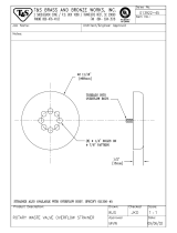
3 0133000 NYLATRON WASHER (2 PLACES)
12 0200500 SMALL MANIFOLD
4 0132500 HEX NUT
13 0194500 SPRAY TUBE (16 PLACES)
5 0133500 SNAP RING
14 0201000 LARGE MANIFOLD
6 0137000 LOWER RINSE FEED PIPE
15 0193500 FIXED RACE
7 0137000 RINSE FEED PIPE COUPLING OR NUT
16 0044700 HOLDING NUT
8 0186500 WASH CAP
17 0188500 HOLDING BOLT (BEFORE S/N 4105)
9 0187000 WASH CAP SET SCREW
17A 0188601 HOLDING PIN (AFTER S/N 4105)
18
WASH HEAD BASE

TIMER FOR MODEL 150 DISHWASHER!
General Description
The timer is a self-contained (frame-mounted) timer of the repeating cycle type. It is mounted in the
control box of Jackson Automatic Dishwashing machines to control the automatic functions of these
machines. It consists of a clock motor which operates on 60 cycle AC. 208/220 VAC. In addition to the
clock motor, the timer also contains a driven cam arrangement which operates four micro switches.
Principle of Operation
The timer controls various operations of the automatic washers as per wiring diagram for each
machine, however, the timing cycle and the micro switches are the same for each model. The time for ONE
COMPLETE REVOLUTION of the cam shaft is approximately 60 seconds, allowing one wash and one
rinse operation for each complete revolution of the cam shaft. The micro switch nearest the timer motor is
the hold circuit and uses both the NO and NC contacts. The second micro switch is the total cycle circuit
and uses both the NO and NC contacts. The third micro switch controls the wash and uses both the NO
and NC contacts- The micro switch farthest away from the timer motor controls the rinse and uses just the
NC contact
Service Instructions
CAUTION: ALWAYS REMOVE THE POWER TO THE MACHINE BEFORE WORKING IN THE CONTROL BOX OR
WHILE SERVICING THE COMPONENTS IN THE POWER BOX. ALL ELECTRICAL CHECKS SHOULD
BE MADE BY QUALIFIED PERSONNEL
Timer operation can be observed after removing the covers from the control box by loosening the
two screws holding each cover in place.
If it is determined that the timer is defective, it is recommended that a new timer be installed.
However, limited field maintenance can be accomplished as follows:
A frozen contact on a micro switch will be indicated by one function being executed all the time or the
absence of a click when the switch arm is actuated. The micro switch is replaced by:
For Bristol-Saybrook Timer
Remove micro switch by moving terminal end of switch away from cams about 1/4" and pulling switch
straight out. Replace new switch in reverse order.
For Eagle Signal Timer:
1. Remove all wires from the timer, properly tag them to assure proper replacement.
2. Remove the two screws which hold the timer to the control box.
3. One screw holds the micro switches, cams and actuating arms in the frame. This screw is seen on the
side opposite the motor. Remove this screw. NOTE: Be sure to note which cam goes with which micro
switch.
4. The unit can now be taken apart and the defective micro switch replaced.
5. Reassemble. NOTE: The flanges on the cams are such that they only mesh in one direction. The shorter flange on
the cams always points toward the drive motor.
The timers cam drive system is equipped with a clutch to enable one to view the operations of the cams and micro
switches. Remove power to machine BEFORE touching timer. Rotate cams by turning with fingers; cams will turn in
one direction only. Do not force them. As cams actuate switches, listen for the click of the switch or test the switches
with an ohmmeter.
12

DEFECTIVE TIMER MOTOR
A defective motor is indicated by the fact that the cams do not rotate or the machine does not
perform the automatic operations or performs a specific part of the cycle continuously, but works okay
on manual. Remember, the timer motor is controlled by the start switch and the hold micro switch,
check this complete circuit before changing motor. The motor is replaced by:
1. Remove motor leads from connection points.
2. Remove the two screws which hold the motor.
3. Replace the new motor.
4. Re-connect motor leads to proper points.
NOTE: It may be necessary to remove complete timer to replace motor; if so, follow steps 1 and 2 on
previous page.
TYPICAL TIMER SWITCH P/N 0177500
13
TIMER P/N 0173900

FUNCTION of SWITCHES, CIRCUIT
BREAKER and INDICATING LIGHTS
Rated 15 amps, controls power to control circuit only, I.E. timer, relays, solenoid
valve, water-level control and motors. Circuit breaker does not cut off power in
power unit box at incoming terminal board and rinse heater or its relay contacts.
Power is still applied to them when the circuit breaker is in "off" position.
This switch interrupts all power going to the control circuit; this means that all
switches on control panel are inoperable until switch is turned "on."
This switch controls the timer motor and has three positions. The start position
(right-hand side) is spring-loaded and is used to initiate the automatic cycle. In the
event of timer failure, the left side of the switch must be engaged to disable the
timer for manual mode of operation.
This switch is used to initiate either a manual wash or rinse operation as well as
initiate the initial fill of the machine. Depressing the left side of this switch will
cause the wash pump to run until returned to the center position. The prime
purpose of this switch position is to extend the wash period for extremely soiled
dishes before putting them through its normal automatic cycle. The right side of
this switch is spring-loaded and must be held down for manual rinse operation; it
however needs only to be depressed momentarily to initiate the automatic fill of
the machine. Either position may also be used as an emergency back-up should
the timer fail to operate, in which case the cycle switch should be placed in the
manual mode.
This red indicating light remains lit whenever the power switch is on.
This green light comes on only when automatic cycle is ready to start and
extinguishes during cycle.
This amber indicating light comes on during the wash cycle.
This amber indicating light comes on during the rinse cycle.
14
Circuit breaker
P/N 0012000
Power switch
P/N 0162000
Cycle switch
P/N 0158900
Manual Cycle
Switch P/N
0155600
Power light P/N
0083518
Ready light
P/N 0083507
Wash light P/N
0083501
Rinse light P/N
0083501

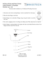
REPLACEMENT of SWITCHES in
CONTROL PANEL
There are three switches installed in the control box front panel. These are the power, cycle, and manual
wash-rinse/fill switches.
Before working on machine, it is important that power be turned off at customer's circuit breaker. To
prevent the possibility of electrical shock, trip breaker to "off" position. Then turn machine breaker
"off" located right side of power box.
Remove the cover from the control box by removing the two screws holding it in place. Remove the
electrical cover from within the control box by removing the two screws holding it in place.
If the switch is found to be defective, insert a new one into the cutout in the control box. Replace the
wires from the used switch terminal by terminal onto the new switch.
Power can now be applied to the dishwasher and run through cycles checking all operations.
15
1.
CONNECTION TERMINALS
2. RETAINING CLIPS
3. FRONT PANEL
4. SWITCH BEZEL
5. ROCKER BUTTON

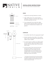
THERMOSTAT ADJUSTMENT
The thermostat can be adjusted by turning screw #1 (see picture) on the thermostat control box
cover. (Remember the present setting, in case the problems are elsewhere in the control circuit.) A CW
rotation is used to obtain a lower temperature setting and a CCW rotation is used to obtain a higher
temperature setting. A 1/8 turn of screw #1 changes the temperature approximately 4°F. If screw #1 is
turned all the way to its stop in either direction, adjust screw #2 as follows. DO NOT TOUCH THE SCREW
SEALED WITH RED PAINT. When adjusting screw #2, power should be disconnected during adjustment.
Set screw #1 so that it can be turned equal distances in either direction, then:
—if screw #1 stopped while turning in CW direction, turn screw #2 in CW direction slowly and
only 1/8 of a turn or less per complete cycle of the unit.
—if screw #1 stopped while turning in CCW direction, turn screw #2 in CCW direction slowly
and only 1/8 of a turn or less per complete cycle of the unit.
Three-fourth's of a turn will bring the thermostat to approximately the same setting obtained where
screw #1 stopped. Check the present temperature setting before attempting any further adjustments. Use
screw #1 for any further adjustments.
. NOTE: Making large moves in adjusting may cause misalignment, thus
increasing the chances that further adjustment cannot be made and the
thermostat will have to be replaced.
16
THERMOSTAT
P/N 0170023 (WASH)
0170023 (RINSE) (SHOWN)

SERVICE INSTRUCTIONS
(INCOMING WATER SOLENOID VALVE)
SOLENOID VALVE
TO TAKE THE VALVE APART
DISASSEMBLY - These valves may be taken apart by
unscrewing the bonnet and the enclosing tube assembly from
the valve body assembly. See Fig. 3. After unscrewing,
carefully lift off the bonnet and enclosing tube assembly. Don't
drop the plunger. The "0" ring seal and diaphragm cartridge can
now be lifted out.
Be careful not to damage the machined faces while the valve is
apart.
TO REASSEMBLE - Place the diaphragm cartridge in the body
with the pilot port extension UP. Hold the plunger with the
synthetic seat against the pilot port. Make sure the "O" ring is in
place, then lower the bonnet and enclosing tube assembly over
the plunger. Screw bonnet assembly snugly down on the body
assembly.
DIAPHRAGM CARTRIDGE P/N 0145500
POSSIBLE PROBLEMS
Pilot Port extension #1 clogged
Hole #2 clogged
REMEDY
Pass heated straight pin through hole #2
or clean hole #1
17
Bonnet
&
Enclosing Tube
Assembly
Plunger Assembly
P/N 0148500
"0"
Ring
P/N 0145500
Diaphragm
Cartridge
Body Assembly
Coil & Housing
Assy. P/N 0144000

RINSE TANK HEATER SYSTEM
FUNCTION
The Rinse Tank Heater System is electrically connected in the circuit so that it is dependent upon
the dishwasher being properly filled with and maintaining a safe water level. The automatic fill system,
therefore, should operate properly before the heat system can be engaged. The circuit is controlled by
a power switch (mounted on the front control panel), a thermostat (mounted behind the lower front
panel), a water level control (mounted in the control box), and a heater relay (mounted in the control
box), with the coil being activated by the thermostat.
INDICATORS OF POSSIBLE MALFUNCTION
Once the machine has been properly filled, the heat circuit should operate by merely turning on
the power switch. Should the rinse tank heat, be it either too high, too low, or no indication of
temperature at all, the following checkouts should be made.
CHECKOUT OF HEATER SYSTEM FOR RINSE TANK (Refer to drawing, figure 1)
NOTE: THE FOLLOWING CHECKOUTS SHOULD BE DONE BY A QUALIFIED SERVICE
PERSON OR ELECTRICIAN.
1. If temperature is too high: adjust thermostat, using thermostat instructions in this manual.
2. If temperature is too low. adjust thermostat as above, then:
a. Turn off power to machine by tripping customer circuit breaker to "off" position.
Turn off machine circuit breaker located on right side of power box.
b. Remove lower cover plate on power box (held by single screw).
c. Make sure rinse temperature is below 180° (preferably about 140°).
d. Turn on both circuit breakers. Observe heat relay (3 or 4 pole, mounted lower left inside
power box) while power switch is turned "on" and "off." If relay contacts move in and
out, see instructions under "B"; if not, proceed with "A."
A: If heat relay does not close:
1. There is an insulated movable bar on the relay across the top of the four contacts. With
insulated probe, depress this bar and observe the rinse thermometer; the temperature should
rise noticeably in a minute or two. If it moves very slowly, it would indicate that one or more
elements are faulty. If it moves constantly higher at a good rate, elements are okay.
NOTE: A check with an amp probe (if available) at position shown in fig. 1, can be made. Each element
should draw 26-28 amps with a total approximate amperage draw of 52-56 amps for both elements.
(Single phase). Replace any defective elements.
A. 2. With power switch on:
a. Check position 1, figure 1. Voltage should be 208-230; if not, checkout heat
switch and replace if necessary.
b. Check position 2; there should be no voltage.
If there is, readjust thermostat per thermostat adjustment instructions.
c. Check position 3; voltage should be approximately 120V to ground.
d. If voltage being applied on positions 1, 2, and 3 checks out okay, then the relay
should be replaced. Coil is probably defective.
18

If heat relay closes:
1. Check power supply at incoming terminal board L1 and L2. It should be 208-230V,
approximately.
2. Check power at positions 4 and 5, fig. 1. Voltage should read approximately 208-230V; if not,
check wires for breaks or bad connections.
3. Check power at positions 6 and 7. Voltage should be approximately 208-230V. If not, check
wires for breaks or bad connections.
4. Temperature should rise as explained in A1 and amperages may be checked according to
those instructions. Replace any defective elements.
FIGURE NO. 1 RINSE HEATER SYSTEM
A. POWER SWITCH
B. WATER LEVEL CONTROL
C. THERMOSTAT
D. HEATER RELAY
E. RINSE TANK HEATERS
F. AMPROBE TEST POSITION
X. TERMINAL BOARD (9 TERMINALS)
SINGLE PHASE
19

WASH TANK HEATER SYSTEM
FUNCTION
The Wash Tank Heater System is electrically connected in the circuit so that it is dependent upon
the dishwasher being properly filled with and maintaining a safe water level. (As an additional safety
precaution, never leave the machine turned on without adequate water nor drain the machine without
first turning off the power switch.) The circuit is controlled by a power switch (mounted on the front
control panel), a water level control (mounted in the power unit box), a thermostat (mounted behind the
lower front panel), and a heater relay (mounted in the power unit box), with the coil being activated by
the thermostat.
INDICATORS OF POSSIBLE MALFUNCTION
Once the machine has been properly filled and the heat system engaged, the heat circuit
should operate by merely turning on the power switch. Should the wash tank be either too high, too
low, or no indication of temperature at all, the following checkouts should be made.
CHECKOUT OF HEATER SYSTEM FOR WASH TANK (Refer to drawing, fig. 2)
NOTE: THE FOLLOWING CHECKOUTS SHOULD BE DONE BY A QUALIFIED SERVICE
PERSON OR ELECTRICIAN.
1. If temperature is too high: adjust thermostat, using thermostat instructions in this manual.
2. If temperature is too low: adjust thermostat, using thermostat instructions in this manual.
3. If step one or two does not correct the problem, proceed as follows:
a. Turn off power to machine by tripping customer circuit breaker to "off" position. Turn machine
circuit breaker on right side of power unit box to "off."
b. Remove cover from power unit box.
c. Reapply power to unit.
d. Wash tank must be emptied, then refilled for each checkout.
e. Wash temperature must be 130 degrees or less. Observe wash heater open switching relay (two
pole), located top relay on left side. Turn power switch on and off; if relay contacts move in and
out, see instructions under BB, if not, proceed.
AA. If heat relay doesn't close:
1. There's an insulated bar across the top of two contacts. With insulate probe, depress this bar
and observe wash thermometer; temperature should rise slowly. Watch for approximately five
minutes; if temperature doesn't rise, replace element. If amprobe E is used, the element should
draw approximately 7 amps.
2. With power switch on:
a. Check position 1, figure 2. Voltage should be 208-230V. If not, check out and
replace heat switch.
b. Check position 2; there should be no voltage. If there is, readjust thermostat per
thermostat adjustment instructions.
c. Check position 3; voltage should be approximately 120V to ground.
d. If voltage being applied on positions 1, 2, and 3 checks out okay, then the relay
should be replaced. Coil is probably defective.
20

BB. If heat relay does close:
1. Check power supply at terminal board #2 between terminals #5 and #7; it should be
approximately 208-230V.
2. Check power at position 4; there should be no voltage.
3. Check position 5; voltage should be approximately 120V to ground.
4. Check power at position 6; voltage should be 208-230V approximately; if not, check wires for
breaks and bad connections.
5. Temperature should rise as explained in AA1 and amperages may be checked according to
those instructions. Replace any defective elements.
FIGURE NO. 2 WASH HEATER SYSTEM
D.
E.
F.
HEATER RELAY
AMPROBE TEST POSITION
WASH TANK HEATER
A.
B.
C.
POWER SWITCH
WATER LEVEL CONTROL
THERMOSTAT
X. TERMINAL BOARD (9 TERMINALS)
21
/