Page is loading ...

CONTENT
Self- Assembly
4-5
Overview
1-3
Setup
6-14
Model: QB-35US3R
4-BAY RAID ENCLOSURE
RAID Modus Einstellungen / LED Anzeigen
Initialization
15-24
Windows Vista / Windows 7 / Macintosh O.S. 10.X
References
25-28
http://www.fantec.de
If you have questions or need help with this device,
please visit our Fantec Support Forum:
http://www.fantec-forum.de/
Please visit our website for more information:
English

DE - 01/38
DE - 02/38
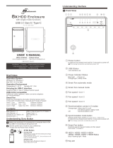
DIAGRAM of FANTEC QB-35US3R
FRONT PANEL
DESCRIPTION
LED INDICATION
1. Blue Power on
Orange Sleep mode
2. Rebuild
3. HDD error When any of HDD1~HDD4 has error, HDD error is on.
4. RAID 0 Spanning Mode / BIG
5. RAID 0 Striping Mode
6. RAID 1
7. RAID 3
8. RAID 5
9. RAID 10
10. Power button It needs to be pressed for 3 seconds to power off.
This design prevents accidental power off.
11. eSATA in use / access
12. USB in use / access
13. HDD Handle
14.-17. HDD1 / HDD2 / HDD3 / HDD4
Blue active
Purple access
Red rebuild
18. Smart Fan automatic mode
19. Smart Fan manual mode
20. Fan speed level 1
21. Fan speed level 2
22. Fan speed level 3
23. Mode RAID mode button needs to be pressed for 3 seconds to
switch the device's mode. This design will prevent
accidental execution of this function.
24. Fan button Controls auto & manual modes and fan speed from
level 1 to level 3.
25. HDD1 error
26. HDD2 error
27. HDD3 error
28. HDD4 error
OVERVIEW
EN - 01/28
EN - 02/28

Quick installation guide
SELF-ASSEMBLY
C. Press down the rib to detach the metal
frame and remove it.
A. Please use the provided handles to
secure the 4 HDDs with screws.
B. Press the circular deepening to open
the cover.
DESCRIPTION
1. Fan
2. RAID CONFIRMATION button
3. USB 3.0 / 2.0 port
4. eSATA port
DESCRIPTION
1. DC Jack
2. DC Power
HDD HANDLE FRONT COVER METAL FRAME
REAR PANEL
SIDE PANEL right
EN - 04/28EN - 03/28
1
2
3
2
4
1
2
1

EN - 05/28
D. Take the transport paper
board out of the device.
E. Slide 4 HDDs into the chassis and
make sure they are securely
installed in order from up
to down.
F. Adjust the metal frame that was removed
in Step C. Please make sure the
bottom of the frame stays
inside the track before
closing the cover.
G. Connect the power supply to the device, plug in either USB, Firewire or eSATA
cable in the rear panel and power on the device.
H. Set up RAID Mode.
EN - 06/28
First install the HDD from up to down in the enclosure. Power on the device,
press RAID button for 3 seconds until LED flashes. Press it again, select the RAID mode
you want to use and press the Confirmation Button on the rear panel till the device shuts down.
Power the device on again and the RAID mode setup is completed.
SETUP
RAID mode setup
2xHDD
3xHDD
4xHDD
No. of HDDs
RAID MODE
RAID 0 (Spanning)
RAID 0 (Striping)
RAID 1 (Mirroring)
RAID 3
RAID 5
RAID 10
: Supported : N/A
RAID mode confirmation button

2TB
2TB
2TB
2TB
8TB
EMPTY
XOR PARITÄT
2TB
2TB
2TB
4TB
2TB
2TB
2TB
XOR PARITÄT
2TB
6TB
2TB
2TB
EMPTY
EMPTY
MIRRORING
2TB
8TB
2TB
2TB
2TB
2TB
STRIPING
2TB
2TB
2TB
2TB
MIRRORING
4TB
MIRRORING
EN - 07/28 EN - 08/28
Spanning
RAID O
RAID O
Striping
Mirroring
RAID 1
RAID 3
Striped set
with dedicated parity
RAID 5
Striped set
with distributed parity
RAID 10
Mirroring +
Striping
Spanning concatenates multiple hard drives as a single large volume; resulting in a seamless
expansion of virtual volumes beyond the physical limitations of separately connected
hard drives. Thze data are written frim HDD1 to HDD4.
Striping is a method of concatenating multiple hard drives into one logical storage unit.
It is the automated process of writing data across multiple drives simultaneously.
Striping is used to increase the performance of disk reads. The multiple hard drives will
write data in “column” e
ffect. If one drive in a striped set fails, all of the data in the stripe
set is lost.
Mirroring is the automated process of writing data to multiple drives simultaneously.
Mirroring is used to provide redundancy. If one drive fails, the redundant drive(s) will
continue to store the data and provide access to it. The failed drive can then be
replaced and the drive set can be rebuild.
This mechanism provides an improved performance and fault tolerance similar to
RAID 5 but with a dedicated parity disk rather than rotated
parity stripes.
The single parity disk is a bottle-neck for writing since every write requires updating the
parity data. One minor benefit is the dedicated parity disk allows the parity drive to
fail and operation will continue without parity or performance penalty.
Distributed parity requires all drives but one to be present to operate; drive failure
requires replacement, but the array is not destroyed by a single drive failure.
Upon drive failure, any subsequent reads can be calculated from the distribute
d parity
such that the drive failure is masked from the end user. The array will have data
loss in the event of a second drive failure and is vulnerable until the data that was
on the failed drive is rebuilt onto a replacement drive.
RAID 10 is mirrored(Raid 1) sets in a striped(Raid 0) set .

Purple / Transferring Data
Purple / Transferring Data
EN - 10/28
EN - 09/28
LED Display Status
MODE LED Display
Spanning
RAID O
When any of HDD1 ~ HDD4 is recognized by the PC,
HDD1 ~ HDD4 blue / active is on.
Blue / Active
RAID O
Striping
LED Display Status
MODE LED Display
When any of HDD1 ~ HDD4 is recognized by the PC,
HDD1 ~ HDD4 blue / active is on.
Blue / Active

Blue / Active
Purple / Transferring Data
Blue / Active
Purple / Transferring Data
LED Display Status
LED Display Status
EN - 11/28
Mirroring
RAID 1
When any of HDD1 ~ HDD4 is recognized by the PC,
HDD1 ~ HDD4 blue / active is on.
MODE LED Display
RAID 3
Striped set
with dedicated parity
MODE LED Display
When any of HDD1 ~ HDD4 is recognized by the PC,
HDD1 ~ HDD4 blue / active is on.
Red / Rebuild
When the data is being rebuilt, LED
of rebuild, HDD error and HDD
(1-4, depends on which HDD
is being rebuilt) error will be on.
Red / Rebuild
When the data is being rebuilt, LED
of rebuild, HDD error and HDD
(1-4, depends on which HDD
is being rebuilt) error will be on.
EN - 12/28

EN - 13/28
EN - 14/28
Purple / Transferring Data
Purple / Transferring Data
Blue / Active
Red / Rebuild
When the data is being rebuilt, LED
of rebuild, HDD error and HDD
(1-4, depends on which HDD
is being rebuilt) error will be on.
Red / Rebuild
When the data is being rebuilt, LED
of rebuild, HDD error and HDD
(1-4, depends on which HDD
is being rebuilt) error will be on.
When any of HDD1 ~ HDD4 is recognized by the PC,
HDD1 ~ HDD4 blue / active is on.
MODE LED Display
RAID 5
Striped set
with distributed parity
LED Display Status
MODE LED Display
When any of HDD1 ~ HDD4 is recognized by the PC,
HDD1 ~ HDD4 blue / active is on.
LED Display Status
Blue / Active
RAID 10
Striped sets
in a mirrored set

DE - 25/38
EN - 16/28
INITIALIZATION
1. Start disk initialization.
If the HDD is uninitialized, you may
have to initialize it by doing steps as
followed: At first click “Start”, “Execute”
at your PC and key in “diskmgmt. msc”.
After that please press “RETURN” key.
Windows 2000 / XP (32 / 64 bit)
Windows 2000 / XP (32 / 62 bit) only support MBR.
Under Windows 2000 / XP, the HDD total volume shall not be more than 2,048GB,
otherwise the device won't be recognized.
EN - 15/28
3. Disk format completed.
2. Create new partition and format disk.

EN - 17/28
EN - 18/28
Windows Vista (32 / 64 bit)
If the HDD is uninitialized, you may have to initialize
it by doing steps as followed: At first click “Start”,
“Execute” at your PC and key in “diskmgmt. msc”.
After that please press “RETURN” key.
1. Start disk initialization.
2. Create new partition and format disk.
3. Disk format completed.
Note: Please enable GPT* if the total capacity is more
than 2TB and enable MBR if the total capacity
is less than 2TB.
GPT mode*: Get more information on page 20.

EN - 19/28
EN - 20/28
Windows 7 (32 / 64 bit)
If the HDD is uninitialized, you may have to initialize
it by doing steps as followed: At first click “Start”,
“Execute” at your PC and key in “diskmgmt. msc”.
After that please press “RETURN” key.
1. Start disk initialization.
Activate MBR if total volume size is up to 2TB
Note: Please enable GPT if the total capacity is more than 2TB and enable MBR if the
total capacity is lup to 2TB.
Initialization with GPT or MBR mode.
Activate GPT if total volume size is more than 2TB

DE - 31/38
2. Create new partition and format disk.
3.HDD format completed
EN - 21/28
EN - 22/28
Macintosh O.S. 10.X
1. Click Disk Utility icon.
2. HDD initialize...

EN - 23/28
5. HDD format in process
6. Format completed
4. Click Erase
3. Click Erase
EN - 24/28

EN - 26/28
EN - 25/28
Positive
(electrode)
Negative
(electrode)
1. Changing the RAID mode will cause data lost.
2. Please refer to the instructions when switching the RAID mode, otherwise the execution might fail.
3. Interface of USB or eSATA can not be used at the same time.
4. When using RAID function, HDDs with the same brand, model and capacity is recommended.
5. When using RAID function, more than one HDD partition is not recommended.
6. Windows Vista/7 users can enable GPT when initializing HDD with a total capacity of more than 2TB.
7. Older OS may not recognize the device if you use a different operation system than Windows Vista.
For more detailed information about GTP, please visit:
http://www.microsoft.com/whdc/device/storage/GPT_FAQ.mspx
8. If you enable MBR by mistake, in order to clean the partition table, you have to switch
another RAID mode and do the RAID mode switch all over again referring to Setup. Then go
back to the RAID mode you want, repeat the previous actions and enable GPT when initializing HDD.
9. For Macintosh users: the total capacity of more than 2TB could be recognized only for the
operation system is 10.4.11 Tiger or later.
10. Do not connect the device to the SATA on board port of the motherboard. Either use SATA to eSATA
PCI-Express or SATA to eSATA PCI add-on card, otherwise the PC may not recognize the device.
11. In RAID 1, HDD1 and HDD2 must be installed, otherwise the PC can not recognize the device.
12. Rebuild time is based on the capacity, e.g. it takes about 1 hour for 200GB.
13. When the USB or eSATA cable is plugged out, the device goes to sleeping mode
automatically.
14. To take the HDD out from the device, slightly press down the handle of the tray and pull it out.
REFERENCES
15. Setting up motherboard's power management in S3 is recommended.
(For more details, please refer to the user guide of motherboard BIOS setting).
16. If the device takes too long to initialize, please check if the HDD is securely installed or
update the eSATA host driver version.
17. If the transfer rate is not normal, please check if the setting of SATA disk jumper is 1.5 or 3.0Gbps .
18. If there is noise with the fan, power off the device, unscrew the fan, take out the cover ,
clean the fan and assemble it back.
19. If the noise is still present, you can change the fan with another identical fan of size 80x80x20mm
referring to Figure-2.

20. If you have forgotten to attach the metal frame before you closed the cover, simply press down
the rib and the cover will slowly release and open outwards. Please do not attempt to pull the
cover with something sharp.
21. If the fan stops working, do not dismantle it. Please send back to the retail store immediately.
22. Temperature -20 ~ 60 °C
Humidity 90 % RH
23. Smart fan controlled by the built-in thermal sensor and it comes with 2 modes (auto / manual)
and 3 levels of speed:
Level 1 : below 45 °C 1200-1800rpm
Level 2: 45 °C ~ 54 °C 1800-2500rpm
Level 3: hotter than 55 °C 2500-3500rpm
24. Operation System:
Windows 2000 / XP / Vista/7 32/64bit ( with MBR enabled, supports total capacity up to 2TB )
Vista/7 32/64bit ( with GPT enabled, supports total capacity more than 2TB )
Macintosh 10.3.x or later
25. Support USB transfer speeds of Low speed (1.5Mbps), Full speed (12Mbps),
High Speed (480Mbps), Super Speed (5Gbps), eSATA transfer speed (1.5~3.0Gbps).
EN - 27/28
26. The chart below shows you that the device still functions when one HDD has error.
RAID MODE
RAID 1
RAID 3
RAID 5
When one HDD has error, the device still functions well
but you may have to replace it with a new one immediately.
27. RAID 10
a) When one HDD has error, the device still functions well but you may have to replace it
with a new one immediately.
b) The chart below shows you that the device still functions when two HDDs have error.
: HDD installed
Error 1
Error status
HDD No.
HDD 1
HDD 2
HDD 3
HDD 4
RAID MODE
Status of device
OK OK OK LOSS
Error 2 Error 3 Error 4 Error 5 Error 6
OKOK
RAID10
Error status
HDD No.
HDD 1
HDD 2
HDD 3
HDD 4
RAID MODE RAID10
Status of device
LOSS OK
Error 7 Error 8 Error 9 Error 10 Error 11
OK OK OK
EN - 28/28
/