Page is loading ...

800-447-8638
Safety Guidelines
Read this manual and these safety guidelines. Learn the applications and limitations of the tool
as well as the hazards specic to it. Operating the tool before understanding safe and proper use
could result in personal injury. SAVE THIS MANUAL.
• Always wear eye, hearing, and respiratory protection specically designed and certied as safety
equipment.
• The drill bit is sharp. Handle with care.
• Avoid awkward hand positions where a sudden slip could cause contact with the rotating bit.
• Properly secure your workpiece before drilling. When using the drill guide independently of the
jig base, do not attempt to hold the drill guide in place by hand. Always use a clamp.
• Follow your drill manufacturer’s safety guidelines.
• Do not operate this tool or any machinery while under the inuence of drugs, alcohol, or
medications.
• Do not allow familiarity gained from frequent use of your tools to replace safe work practices. A
moment of carelessness is sufcient to cause severe injury.
Owning a Kreg Jig
®
opens up new project possibilities. This manual shows you how to adjust your
jig and drill pocket holes. You may nd the following resources helpful:
Kreg Tool Online
kregtool.com. Find it all here: product information, videos, tips, project plans, and more.
Kreg Owner’s Community
kregjig.ning.com. Join thousands of enthusiastic Kreg owners who swap tips and advice, share
their projects, and more.
Kreg Newsletters: Sign up for our free email newsletters at kregtool.com.
• Kreg Plus: Your source for handy woodworking and DIY tips and tricks, project ideas, and much more.
• Kreg Tool News: Stay up to date on the latest Kreg tools and learn about special offers.
• Kreg Community News: Learn about projects being built in the Kreg Owner’s Community, and
get free plans.
Introduction
1
WARNING:
!
This product can expose you to chemicals including Acrylonitrile and other chemicals,
which are known to the State of California to cause cancer and reproductive harm. For more information
go to www.P65Warnings.ca.gov.
WARNING:
!
Drilling, sawing, sanding or machining wood products can expose you to wood dust, a
substance known to the State of California to cause cancer. Avoid inhaling wood dust or use a dust mask or other
safeguards for personal protection. For more information go to www.P65Warnings.ca.gov/wood.

www.kregtool.com
Parts
Additional Master System Parts
Your Kreg Jig
®
K5 or K5 Master System is almost ready to use right out of the box. Apply the
screw-length selection guide label to the inside of one extension lid. Place the jig on your
workbench and t the dovetail keys on the extensions into the dovetail slots in the base. The jig
and extensions feature holes for mounting to a board.
A
B
C
D
E
F
G
H
I
J
K
L
M
N
O
P
Q
R
S
T
U
V
W
X
Y
S
2

800-447-8638
K5 and K5 Master System Parts
Base
Features four holes for securing the jig to a workbench or auxiliary base
Drill-guide socket
Accepts all Kreg drill guides: Micro, Standard (included), and HD
Toggle handle
Operates workpiece clamping mechanism
Clamp assembly
Powerful internal spring applies clamping pressure
Ratchet plate
Provides clamp-assembly adjustment
Ratchet release
Disengages clamp assembly from ratchet plate
Standard drill guide
Features marks for positioning the guide for different workpiece thicknesses
Locking pin
Spring-loaded pin locks the drill guide into the drill-guide socket at the selected setting
Step bit
Simultaneously drills a pilot hole and clearance hole, forming a bearing shoulder for
the screw head
Stop collar
Controls drilling depth
Hex wrench
For the stop-collar set screw
Stop-collar setting block
Ensures proper positioning of the depth collar on the drill bit
Driver bit
#2 square-drive bit 6" (152mm) long
Workpiece stop
Stop snaps into keyhole slots in the base
Workpiecestopne-adjustmentnut
¼-20nuttsintohexrecessinworkpiecestop
Knurled nut
Nylonknurlednutactsasjamnuttoxthepositionofthene-adjustmentscrew
Fine-adjustmentscrew
¼-20x2½"(64mm)nylonboltthreadsintonuttoprovideno-slipneadjustment
Parts
A
B
C
D
E
F
G
H
I
J
K
L
M
N
O
P
Q
3

www.kregtool.com
K5 and K5 Master System Parts
Vacuum port
Acceptsa1¼"(32mm)shopvacuumhoseforefcientchipremoval,swivelssidetoside
Extension Wings
Provide support for wide workpieces and storage for bits and accessories
Screw-length selection guide
Apply this self-adhesive label to the inside of an extension lid for easy reference
Spacer block
In repair applications, positions the drill guide for drilling pocket holes in
¾" (19 mm)-thick material
Pocket-screw sample pack
Contains10eachofthevemostoftenusedscrews
Pocket-hole plug sample pack
Containsvepaint-gradewoodplugs
Additional Master System Parts
The K5 Master System includes the following parts
Portable base
Accepts Micro, Standard, and HD drill guide blocks. Useful for large panels or
assembliesthatwouldbedifculttoclampintoabench-mountedjig.Built-incams
secure the portable base to your Kreg clamp.
3"WoodProjectClampwithAutomaxx
®
Provides fast and secure clamping when assembling a pocket-screwed joint. Set
the desired pressure and this 3"-reach clamp automatically adjusts to any
material thickness up to 3" (76mm).
Parts
R
S
T
U
V
W
X
Y
Tocreatestrongjoints,you’llsetyourjigtomatchthe
thickness of the workpiece and the length of the screw.
The Kreg Jig
®
makesthiseasy,injustfoursimplesteps:
Using the Kreg Jig
®
K5 and K5 Master System
4

800-447-8638
Using the Kreg Jig
®
K5 and K5 Master System
Set the Drill Guide
For a strong joint, the screw should exit close to the center of
the workpiece. To adjust the pocket-hole position, retract the
spring-loaded drill-guide locking pin (H). Then raise or lower
the drill guide (G) until the mark on the side of the guide that
matches the thickness of the workpiece is even with the top
oftheguidesocket(B).Releasethelockingpin.
1
G
B
H
Fine Thread
Because the smaller diameter and thread
pitch of our #7 ne-thread screws reduce
the chance of splitting the material, we
recommend them for hardwoods.
Use in woods such as:
• Ash • Oak • Maple • Walnut • Hickory
• Cherry • Mahogany • Birch
2
All Kreg pocket screws feature a deep square drive that improves driver engagement and reduces the
possibility of cam-out. The self-tapping auger point eliminates the need to drill a pilot hole.
Coarse Thread
Due to the large diameter and thread pitch,
our #8 coarse-thread screws offer a strong
hold in softwoods and composite materials.
Use in woods such as:
• Pine • Cedar • Basswood • Poplar
• Plywood • Melamine • Particle Board
Screw Selection / Kreg Jig
®
Setting Chart
Material Thickness Screw Length Kreg Jig
®
Setting
1
⁄2" [13 mm]*
1" [25 mm]**
1
⁄2" Mark
5
⁄8" [16 mm] 1" [25 mm]
5
⁄8" Mark
3
⁄4" [19 mm] 1
1
⁄4" [32 mm]
3
⁄4” Mark
7
⁄8" [22 mm] 1
1
⁄2" [38 mm]
7
⁄8" Mark
1" [25 mm] 1
1
⁄2" [38 mm] 1” Mark
1
1
⁄8" [29 mm] 1
1
⁄2" [38 mm] 1
1
⁄8” Mark
1
1
⁄4" [32 mm] 2" [51 mm] 1
1
⁄4" Mark
1
3
⁄8" [35 mm] 2" [51 mm] 1
3
⁄8" Mark
1
1
⁄2" [38 mm] 2
1
⁄2" [64 mm] 1
1
⁄2" Mark
Kreg offers a complete line of pocket screws for every workpiece thickness and type. Use this chart to select the
correct screw length. All Kreg pocket screws are available at your Kreg dealer or online at kregtool.com.
Choose a Screw
Your KREGprojects demand KREG Screws. Learn why at kregtool.com/kregscrews
5
Note: Screw length is measured from bottom of the head to the tip of the screw.
1
1
⁄4" (32mm)
**When using optional Micro-Pocket™ Drill Guide,
3
⁄4″ screws
are recommended for
1
⁄2″ material. See Micro Owner’s manual
*Panhead pocket screw recommended.

www.kregtool.com
Using the Kreg Jig
®
K5 and K5 Master System
Position the Stop Collar
Place the stop-collar setting block (L) on the jig base in
front of the drill guide. Slide the step bit (I) into one of the
drill guide bushings and drop the pilot tip into the hole in the
block that corresponds to the length of the screw you’ll be
using. With the step bit shoulder resting on the block, slide
the stop collar (J) onto the drive-end of the bit so it rests on
the drill guide. Tighten the stop collar set screw with the hex
wrench (K).
Use the chart below as a guide for positioning the drill-bit
stop collar when using the standard drill guide and bit as
well as the optional Micro Pocket Drill Guide and bit and
Kreg Jig
®
HD drill guide and bit. Always make a test joint
withstockthesamethicknessasyournishedworkpieces
before proceeding with your project.
3
K
J
I
L
Example:
3
⁄4" (19mm) board, 1
1
⁄4" (32mm) screw
Drill Guide & Bit Material Thickness Screw Length Setting Block Step
Micro* ½" (13mm) ¾"** ¾"
Micro* & Standard
1
⁄2"-1⅛"(13mm-29mm) 1", 1¼", 1½" 1", 1¼", 1½"
Standard 1¼"-1⅜"
(32mm-35mm) 2" 2"
Standard & HD* 1½"
(38mm) 2½" 2½"
**Use a panhead pocket screw.
Adjust the Clamp Assembly
Press down on the ratchet release (F) and slide the clamp
assembly (D) all the way back. Position the workpiece
against the drill guide. Move the toggle handle (C) to the
full-down (clamped) position. Slide the clamp assembly
forward until the pad contacts the workpiece. (You’ll hear
the adjustment mechanism clicking.)
4
C
F
D
Using the Stop-Collar Setting Block
*optional accessories
Holding the clamp assembly against the workpiece, raise
the toggle handle until you hear the adjustment mechanism
click two times. Move the toggle handle to the clamped
position. Check to make sure the workpiece is securely
held in place. If needed, raise the toggle handle one more
click. The clamp assembly is now positioned so the internal
springappliessufcientpressuretosecuretheworkpiece
when the toggle handle is in the full-down position.
6

800-447-8638
Features
Vacuum Port
Thischip-collectionattachment(R)snapsintoplaceon
the back of the drill guide socket. The port accepts any
standard 1¼" (32mm) vacuum hose and conveniently
swivels from side to side. In addition to helping keep your
workareaclean,efcientchipremovalspeedsdrillingtime
and reduces heat build-up, extending the life of your drill bit.
R
Q
N
P
Kreg Jig
®
K5 Master System Additional Features
Workpiece Stop
For repetitive pocket-hole drilling operations, the stop (N)
snaps into keyhole slots in the base. To install, drop the
pegs on the bottom of the stop into the large end of the
keyhole slots and slide the stop toward the front of the jig.
For precise pocket-hole placement, press the steel nut (O)
into one of the hexagonal recesses in the stop. Thread
the knurled nut (P) onto the nylon bolt (Q) and thread the
bolt into the nut from the opposite side of the stop. The nut
and bolt work together to provide easy adjustment and the
knurled nut locks the bolt in position.
3" Wood Project Clamp with Automaxx
®
These 3" (76mm)-reach clamps automatically adjust
to workpiece thickness up to 3" (76mm). To keep joints
perfectly aligned when driving pocket screws, clamp the
workpiecestoaatsurface,centeringtheclamppadover
the joint line. Adjust the clamp to apply enough pressure to
keeptheworkpiecesushandstablebutnotsotightthat
clampingandunclampingaredifcult.
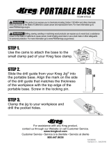
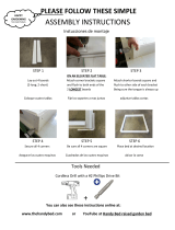
Portable Base
Use this base for large panels or assemblies that would
bedifculttoclampintoabench-mountedjig.Remove
the drill guide from the drill-guide socket and slide it
into the portable base. Align the mark on the side of the
drill guide that matches the thickness of the workpiece
with the top edge of the portable base. Screw in the
locking pin. The base also accepts Micro and HD drill
guideblocks.Built-incamssecuretheportablebaseto
a Kreg clamp.
7

www.kregtool.com
Pocket-Hole Placement
In addition to the proper Kreg Jig
®
settings, spacing pocket holes evenly across the workpiece is an
important part of getting a strong joint. The Kreg Jig
®
features a three-hole drill guide that allows you
do this in a variety of workpiece widths without the need to reposition the workpiece after drilling each
hole. Use the guide below to determine how to position your workpiece for drilling pocket holes.
Beforeturningonthedrill,slidethebitintothedrillguideuntilthetipofthebittouchesthe
workpiece. Withdraw the bit about ¼" (6mm). Turn on the drill, make sure it is running at
full speed, and feed the bit into the workpiece. Always run variable-speed or multi-speed
drills at the fastest speed. A shop vacuum connected to the vacuum port quickly removes
the wood chips and the hole can be drilled in one motion. When not using a shop vacuum,
remove the vacuum port, and while drilling the pocket hole, partially withdraw the bit
several times to clear the chips. Stop drilling when the stop collar contacts the drill guide.
Wait until the drill stops rotating to withdraw the bit from the drill guide.
Forwidepartssuchaspanels,werecommendplacingtherstpockethole2"(51mm)
from the panel edge and every 6" (152mm) to 8" (203mm) on center after that. When
drilling panels, you can use any drill guide hole.
Drilling Pocket Holes
Withthepocketholesdrilled,positionandclampyourparts.Smallatassembliescanbe
alignedbyclampingthemtoaatsurface.WhenusingaKregclamptoclamplargeat
assemblies off the edge of your work surface, position the large clamp pad on the side of the
joint opposite the pocket holes. Align the corners of case assemblies, such as a cabinet or
bookshelf, using bar clamps or a Kreg right-angle clamp. (See Optional Accessories.)
With your assembly securely clamped, drive the pocket screws using a variable-speed
drill/driver and the included 6" (152mm) driver bit. For drills with a clutch, adjust it to fully
seat the screws without over-driving them.
Joining parts
8
1" to 2" Wide Material 2" to 3" Wide Material 3" to 4" Wide Material
Use B and C guides Use A and B guides Use A and C guides
(25mm to 51mm Wide Material) (51mm to 76mm Wide Material) (76mm to 102mm Wide Material)
1" to 2" Wide Material
USE B AND C GUIDES
2" to 3" Wide Material
USE A AND B GUIDES
USE A AND C GUIDES
3" to 4" Wide Material

800-447-8638
Repair Applications
For ½" (13mm)-thick material, align the bottom of the drill
guide with the edge or end of the part to be drilled. For thicker
stock, attach one or more spacer blocks (U) to the drill guide.
Each spacer block accommodates an additional ¼" (6mm)
in material thickness. For example, ¾" (19mm)-thick material
requires one spacer block, 1" (25mm)-thick material requires
two blocks, and 1¼" (32mm)-thick material requires three
blocks. One spacer block is included with your Kreg Jig
®
.
Additional blocks are available.
For repair applications, remove the drill guide from the drill
guide socket and clamp it directly to the workpiece.
U
When using the drill guide separately in a repair application,
remembertosetthestopcollar,andrmlysecurethedrill
guide to the workpiece with a Kreg clamp. In situations where
using a clamp is not possible, you may screw the drill guide
directly to the workpiece, as shown.
Adjusting Clamp Pressure
9
To increase clamp pressure, turn
the knurled-head screw to the
left (viewed from the handle-end
of the clamp); for less pressure,
turn the screw to the right.
Less
Pressure
More
Pressure

www.kregtool.com
Tips
For boards at least 3" (76mm) wide, pocket holes
drilledwiththe“A”and“C”guidesbothtentirely
on the face of the board. In this situation, simply
position the mitered workpiece on the jig, clamp it
in place, and drill.
Mitered Corners
For boards at least 2
3
/8" (60mm) wide, pocket
holesdrilledwiththe“B”and“C”guidesbotht
entirely on the face of the board. In this situation,
simply position the mitered workpiece on the jig,
clamp it in place, and drill.
When using the optional Micro Pocket Drill Guide
and drill bit with ½" (13mm)-thick stock, join the
parts with Kreg SPS-F075 screws. The small-
diameter head of these ¾" (19mm) panhead
screws seats below the workpiece surface to
allow plugging with a Micro pocket-hole plug.
Joining ½" (13mm)-thick stock
To position a pocket screw close to the miter
“toe” on a wide workpiece or to position a second
pocket screw on a narrow workpiece and still
have the hole entirely on the face of the part,
drill the pocket hole closest to the miter heel with
thedrillguideinthedrillguidesocket.Remove
the guide from the socket. For ¾" (19mm)-thick
stock, attach a spacer block (U) to the drill guide.
Position the drill guide with the spacer-block end
1½" (38mm) from the miter toe, and then angle
the drill guide away from the toe at a 30-degree
angle. Clamp the drill guide in place and drill the
pocket hole.
U
1
1
⁄2"
30°
Mitered Corners
You also can drill one pocket hole on each side
of a miter joint rather than drilling both holes on
the same side.
(38mm)
10

800-447-8638
Tips
Nominal Size vs. Actual Size
At a lumberyard or home center you’ll see labels on
lumber such as “1x6” and “2x4.” These “nominal”
sizes once described the dimensions of rough-cut
lumberbeforeitwasmilledtonishedoractualsize.
Actual size is always smaller than nominal size.
The board-thickness marks on your Kreg Jig
®
refer
the actual thickness of the board. For example, a
1x4 is actually ¾" thick, so you’ll set your jig to the
¾" mark.
Common Board Sizes
Nominal Size Actual Size
1x2
3
⁄4" x 1
1
⁄2"
1x3
3
⁄4" x 2
1
⁄2"
1x4
3
⁄4" x 3
1
⁄2"
1x6
3
⁄4" x 5
1
⁄2"
1x8
3
⁄4" x 7
1
⁄4"
2x2 1
1
⁄2" x 1
1
⁄2"
2x4 1
1
⁄2" x 3
1
⁄2"
2x6 1
1
⁄2" x 5
1
⁄2"
2x8 1
1
⁄2" x 7
1
⁄4"
4x4 3
1
⁄2" x 3
1
⁄2"
6x6 5
1
⁄2" x 5
1
⁄2"
3½˝
1½˝
4˝
2˝
Nominal
(2˝ x 4˝)
Actual
(1½˝ x 3½˝)
Length
Width
Thickness
Thickness
Length
Width
Grain Direction
6 Tips to Reduce Wood Splitting
Test Pieces
Testthejointwithscrappiecescutfromthesamestockasyournalworkpiece.
Make sure you’re using Kreg Screws
Kregscrewsfeaturesharp,self-tappingtipsthatslicethroughthewoodbers.
Use the Right Screw Type
Usene-threadscrewsinhardwood.These#7screwsdisplacelesswoodthanthe#8coarse-
thread screws that are used for softwood, plywood, MDF, and particleboard.
Drive Progressively
Drivethescrewhalf-wayin,backitouttoclearexcesswoodbersfromthehole,andthendrive
the screw all the way in.
Reduce Friction
Apply bee’s wax or other lubricant to the screw to reduce the friction as the screw enters the
workpiece.
Clamp Correctly
Center the clamp pad on the joint line to apply equal pressure to both workpieces and keep them from
shifting. Firm clamping pressure forces the screw to slice through the wood instead of splitting it apart.
1
2
3
4
5
6
11

www.kregtool.com
Optional Accessories
Available from your Kreg dealer or online at kregtool.com
Micro Pocket
™
Drill Guide
With a hole diameter 25% smaller than our standard pocket hole,
the Micro Pocket
™
Drill Guide lets you create compact pocket holes
in small projects, thin stock, and tight repair applications.
Kreg Jig
®
HD
Designed for use with 1
1
⁄2" (38mm)-thick and thicker framing material,
this heavy-duty system features #14 x 2 ½" (64mm) pocket screws.
6" Wood Project Clamp with Automaxx
®
Set the desired pressure and these 6" (152mm)-reach clamps
automatically adjust to materials up to 5" (127mm) thick.
Quick Change Kit
Switch from drilling pocket holes to driving pocket-hole screws in
seconds. The quick-change chuck installs in any three-jaw drill
chuck to accept standard ¼" (6mm) hex-shank bits.
Right-Angle Clamp with Automaxx
®
Slip the steel-pin jaw of this clamp into a pocket hole to clamp
workpieces together at a 90-degree angle. Then drive a screw into
an adjacent pocket hole.
Kreg System Organizer
Keepyourentirepocket-holeworkshopinthiscompact,ttedcase.
Accommodates K3, K4, or K5 pocket-hole jigs, Kreg clamps, Micro,
HD, and plug cutter drill-guide blocks, drill and driver bits, and an
assortment of pocket screws.
12

www.kregtool.com
/