Page is loading ...

KVH, TracPhone, IP-MobileCast, CommBox, and the unique light-colored dome with dark contrasting baseplate are trademarks of KVH
Industries, Inc. All other trademarks are property of their respective companies. The information in this document is subject to change without
notice. No company shall be liable for errors contained herein. © 2019-2022 KVH Industries, Inc., All rights reserved. 54-1231 Rev. J 1
AgilePlans® by KVH
TracPhone V7HTS Antenna and Ancillary Equipment
Reshipping Instructions
Getting Help
If you need assistance, please contact KVH’s Agile Orders Group at [email protected]m.
This guide explains how to prepare a TracPhone® V7-HTS antenna system, including the antenna, ICM, and
any accessories (i.e., the KVH Link Set-top Box, Thales® VesseLINK™ 200/700 system, Iridium Pilot® system,
SAILOR® 4300 system, or Media Server) for shipping.
Packing Steps
The complete listing of packing steps is provided below.
Important!
These instructions assume the equipment has been removed from the vessel and that you have access to the
original packaging or the KVH shipping kits (KVH part nos. 72-0869-01 and 72-0869-02). If all essential
components are not returned, or if the equipment is damaged and/or does not function normally, you
will be billed for the cost of replacement or repairs.
1. Pack the ICM..............................................................2
2. Pack the Antenna.......................................................3
3. Pack the KVH Link Set-top Box (if applicable)...10
4. Pack the VesseLINK 200 (if applicable) ...............12
5. Pack the VesseLINK 700 (if applicable) ......... 15
6. Pack the SAILOR 4300 (if applicable) ............ 18
7. Pack the Iridium Pilot (if applicable) ............. 21
8. Pack the Media Server (if applicable)............. 24
Tools Required
This procedure requires the following tools:
• The original packing material you
received with the equipment
• Phillips screwdrivers
• 1/2" open-end wrench
• 3/4" socket/ratchet or wrench
• 3/4" socket/torque ratchet capable of
settings between 25 and 30 ft-lbs (34 and
41 N-m) of torque
• Loctite C5-A anti-seize lubricant (or equivalent)
• 7/16" open-end wrench for J4 RF terminator
• Extraction tool or equivalent for B1-to-B2 locking jumper
cable

2
Pack the ICM
The following items must be returned:
Integrated CommBox Modem (ICM)
Quantity: 1
Follow the instructions below to prepare the ICM
for shipping.
a. Remove the power cable, Wi-Fi antennas, RF
terminator, Ethernet jumper cable, and strain-
relief bracket from the ICM.
NOTE: Use an extraction tool to remove the locking
Ethernet jumper cable from the B1 and B2 jacks.
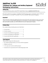
b. Place the ICM in a polybag. Then enclose the
ICM with foam end caps (see Figure 1).
c. Place the ICM into the shipping box. Close
and seal the box.
d. On the outside of the shipping box, clearly
write the RMA number.
e. If you are using the original packaging to
return the antenna, you will pack the ICM
with the antenna as described in “Using the
Original Antenna Packaging” on page 4.
If you are using the KVH shipping kit to
return the antenna, the ICM is now ready to
ship.
NOTE: Shipments received without an RMA number
will be returned to you at your expense.
Using Incoterms DDP, ship the ICM to the
address provided by the KVH Agile Orders
Group.
Figure 1: ICM Box Ready for Shipping

3
Pack the Antenna
The following items must be returned:
TracPhone antenna
Quantity: 1
Follow the instructions below to prepare the
antenna for shipping.
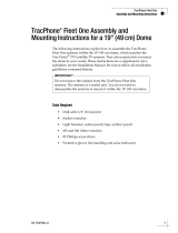
a. Remove the six #10-32 screws securing the
radome to the baseplate (see Figure 2).
Carefully lift the radome straight up until
clear of the antenna assembly and set it aside
in a safe place.
NOTE: The two hoisting eyelets on the antenna frame
may be used to lift the antenna, if necessary (see
Figure 3). Make sure they are undamaged and free of
cracks before using them.
Hoisting
Eyelets (x2)
Figure 3: Antenna Hoisting Eyelets
b. If you are using the original packaging to
return the antenna, continue to “Using the
Original Antenna Packaging” on page 4.
If you are using the KVH shipping kit to
return the antenna, continue to “Using the
Shipping Kit” on page 8.
#10-32 Screw (x6)
Figure 2: Radome Screws

4
Using the Original Antenna Packaging
a. If you are using the original antenna
packaging to return the antenna, begin by
positioning the antenna over the holes drilled
in the shipping pallet. Then carefully lower
the antenna onto the pallet and ensure the
mounting holes are aligned (see Figure 4).
c. At each of the four antenna mounting holes,
insert a 1/2"-13 bolt from above and a 1/2"
T-nut from below (see Figure 5).
d. Secure each bolt through the shipping pallet
and into the T-nut until the T-nut bottoms
against the shipping pallet. Make sure the
bolt heads are flush with the antenna’s
stationary plate before proceeding.
e. Tighten the mounting bolts in a cross pattern
until the four rubber feet on the baseplate are
bottomed against the shipping pallet. KVH
recommends that you tighten the nuts to
between 18 and 20 ft-lbs (24 and 26 N-m) of
torque.
f. Carefully wedge the foam shipping restraint
underneath the reflector to ensure the
reflector is secure during transit. The reflector
should rest within the shipping restraint’s
notch (see Figure 4).
CAUTION
Be sure to observe the safe handling
instructions in the Material Safety Data Sheet
(MSDS) provided with the anti-seize
lubricant.
You will need to rotate the antenna assembly
slowly by hand to see all four mounting
holes. You will also need to fully install the
first pair of mounting bolts prior to rotating
the antenna assembly to install the second
pair of bolts. If the antenna assembly hits a
mechanical stop with excessive force, or it hits
the head of a mounting bolt that wasn’t
secured in place, the limit switch might
become damaged.
IMPORTANT!
Figure 4: Foam Shipping Restraint and Pallet Bolts
Foam
Restraint
1/2" Bolt (x4)
Pallet
Notch
Figure 5: Mounting Bolts (Side View)
T-Nut (x4)
1/2"-13 Bolt (x4)
Apply anti-seize to threads
Torque to 25-30 ft-lbs
(34-41 N-m)
Rubber
Foot (x4)
Pallet
Antenna
Baseplate
Stationary
Plate

5
g. Reinstall the radome onto the antenna. Secure
it in place with the six #10-32 screws you
removed earlier (see Figure 2 on page 3).
h. Place the empty cabling box next to the
antenna (see Figure 6).
i. Cover the antenna with a radome bag (see
Figure 7).
j. Place the shipping box over the antenna and
cabling box and down to the shipping pallet
(see Figure 8).
Figure 6: Reshipping Box on Antenna with Empty Cabling Box
Tape
Screw and Washer (x6)
Figure 7: Radome Bag on Antenna
Figure 8: Antenna Shipping Box on Pallet
Tape
Screw and Washer (x6)

6
k. On all four sides of the shipping box, center a
wooden slat at the base of the box. Then
secure the box to the pallet through the slat
with two #10 x 2" drywall screws and
washers, as shown in Figure 9.
l. Insert the ICM box and empty accessories box
in the shipping box on top of the empty
cabling box. (see Figure 10).
m. Fold a cardboard spacer to fit on one side of
the ICM and accessories boxes, then fit a
second spacer at the foot of the boxes (see
Figure 11).
Figure 9: Screws Securing Shipping Box to Pallet
Tape
Screw and Washer (x6)
#10 x 2" Drywall Screw
and Washer (x8)
Figure 10: Identical ICM and Accessories Boxes in Shipping Box
Tape
Screw and Washer (x6)
Figure 11: Rectangular Spacers Around ICM/Accessories Boxes
Tape
Screw and Washer (x6)

7
n. Place four triangular spacers around the
antenna as shown in Figure 12.
o. Close and seal the antenna shipping box (see
Figure 13).
p. On the outside of the shipping box, clearly
write the RMA number.
NOTE: Shipments received without an RMA number
will be returned to you at your expense.
Using Incoterms DDP, ship the antenna and
ICM to the address provided by the KVH Agile
Orders Group.
Figure 12: Triangular Spacers Around the Antenna
Tape
Screw and Washer (x6)
Figure 13: Sealed Antenna Shipping Box
Tape
Screw and Washer (x6)

8
Using the Shipping Kit
a. If you are using the shipping kit to return the
antenna, begin by carefully wedging the
foam shipping restraint underneath the
reflector to ensure the reflector is secure
during transit. The reflector should rest
within the shipping restraint’s notch (see
Figure 14).
b. Reinstall the radome onto the antenna.
c. Remove the foam cap from the antenna
reshipping box, but leave the foam base in
place (see Figure 15).
Figure 14: Foam Shipping Restraint
Foam
Restraint Notch
Figure 15: Foam Base of Antenna Reshipping Box

9
d. Place the antenna in the center of the box so
its baseplate is seated properly within the
foam base (see Figure 16).
e. Enclose the radome with the protective foam
cap (see Figure 16 and Figure 17).
f. Close and seal the box.
g. On the outside of the shipping box, clearly
write the RMA number.
NOTE: Shipments received without an RMA number
will be returned to you at your expense.
Using Incoterms DDP, ship the antenna to the
address provided by the KVH Agile Orders
Group.
Figure 16: Antenna in Center of Box, Placing Foam Cap
Figure 17: Foam Cap in Place

10
Pack the KVH Link Set-top
Box (if applicable)
The following items must be returned:
Set-top Box
Quantity: 1
AC power adapter
Quantity: 1
HDMI cable
Quantity: 1
Remote control
Quantity: 1
Follow the instructions below to prepare the
KVH Link Set-top Box for shipping.
Figure 18: Set-top Box Accessories in Inner Box
a. Remove and discard the batteries from the
Set-top Box remote control.
b. Place the remote control and AC power
adapter in sealed ziplock bags and place the
bags and HDMI cable, along with the
manuals, within the inner shipping box (see
Figure 18). This is the original box from the
manufacturer.

11
c. Place the Set-top Box in a sealed ziplock bag.
Then place it in the cardboard cutout before
placing it in the inner box on top of the Set-
top Box accessories (see Figure 19).
d. Close and seal the inner shipping box.
e. Wrap the inner box in bubble wrap and place
it in the shipping box (see Figure 20).
f. Close and seal the shipping box.
g. On the outside of the shipping box, clearly
write the RMA number.
NOTE: Shipments received without an RMA number
will be returned to you at your expense.
Using Incoterms DDP, ship the Set-top box to
the address provided by the KVH Agile Orders
Group.
Figure 19: Set-top Box in Inner Box
Figure 20: Inner Box Protected in Shipping Box

12
Pack the VesseLINK 200
(if applicable)
The following items must be returned:
Above Deck Unit (ADU)
Quantity: 1
Below Deck Unit (BDU)
Quantity: 1
AC-DC Power Supply
Quantity: 1
Wi-Fi antenna
Quantity: 1
Follow the instructions below to prepare the
Thales VesseLINK 200 system for shipping.
a. Place the BDU in the foam cutout in the BDU
box (see Figure 21).
Figure 21: BDU in Foam Cutout

13
b. Cover the BDU with the layer of protective
foam (see Figure 22). Then close and seal the
box.
c. Place the ADU in the center of the ADU box.
Make sure it is seated in the cutout in the base
(see Figure 23).
d. Place the cardboard collar over the top of the
ADU (see Figure 24). Then close and seal the
box.
Figure 22: BDU Protective Foam
Figure 23: ADU Centered in Box
Figure 24: ADU Cardboard Collar

14
e. Place the BDU box in the bottom of the
shipping box (see Figure 25).
f. Place the ADU box, power supply, Wi-Fi
antenna, and power cable on top of the BDU
box in the shipping box (see Figure 26).
g. Secure all the items in the box with ample
packing paper or bubble wrap (see
Figure 27). Then close and seal the shipping
box.
h. On the outside of the shipping box, clearly
write the RMA number.
NOTE: Shipments received without an RMA number
will be returned to you at your expense.
Using Incoterms DDP, ship the VesseLINK 200
system to the address provided by the KVH
Agile Orders Group.
Figure 25: BDU Box Placed in Shipping Box
Figure 26: ADU, Power Supply, and Wi-Fi Antenna Placed in Box
Figure 27: Packing Material

15
Pack the VesseLINK 700
(if applicable)
The following items must be returned:
Above Deck Unit (ADU)
Quantity: 1
Below Deck Unit (BDU)
Quantity: 1
AC-DC Power Supply
Quantity: 1
Wi-Fi antenna
Quantity: 1
Follow the instructions below to prepare the
Thales VesseLINK 700 system for shipping.
a. Place the ADU in the center of the ADU box.
Make sure it is surrounded by protective
foam (see Figure 28).
Figure 28: ADU Protected in Foam Base

16
b. Cover the ADU with the layer of protective
foam (see Figure 29). Then close and seal the
ADU box.
c. Place the BDU in the foam cutout in the BDU
box (see Figure 30).
d. Cover the BDU with the layer of protective
foam (see Figure 31). Then close and seal the
box.
Figure 29: ADU Protective Foam
Figure 30: BDU in Foam Cutout
Figure 31: BDU Protective Foam

17
e. Place the ADU box in the bottom of the
shipping box (see Figure 32).
f. Place the BDU box, power supply, Wi-Fi
antenna, and power cable on top of the ADU
box in the shipping box (see Figure 33).
g. Secure all the items in the box with ample
packing paper or bubble wrap (see
Figure 34). Then close and seal the shipping
box.
h. On the outside of the shipping box, clearly
write the RMA number.
NOTE: Shipments received without an RMA number
will be returned to you at your expense.
Using Incoterms DDP, ship the VesseLINK 700
system to the address provided by the KVH
Agile Orders Group.
Figure 32: ADU Box Placed in Shipping Box
Figure 33: BDU, Power Supply, and Wi-Fi Antenna Placed in Box
Figure 34: Packing Material

18
Pack the SAILOR 4300
(if applicable)
The following items must be returned:
SAILOR 4300 Above Deck Unit
(ADU)
Quantity: 1
SAILOR 4300 Below Deck Unit
(BDU)
Quantity: 1
BDU power cable
Quantity: 1
Follow the instructions below to prepare the
SAILOR 4300 system for shipping.
a. Place the ADU in the center of the ADU box.
Make sure it is seated in the cutout in the base
layer of foam (see Figure 35).
b. Enclose the ADU with the protective foam
cap (see Figure 36). Then place a thin layer of
foam on top so it is flush with the top of the
box.
c. Close and seal the box.
Figure 35: ADU in Box
Figure 36: ADU Protective Foam

19
d. Place the BDU upside down in the foam
cutout in the BDU box (see Figure 37).
e. Cover the BDU with the thick layer of
protective foam (see Figure 38).
f. In the center cutout of this thick layer of
foam, place the BDU power cable. Then place
a thin layer of foam on top so it is flush with
the top of the box.
g. Close and seal the box.
Figure 37: BDU in Foam Cutout
Figure 38: BDU Protective Foam

20
h. Place the ADU box in the bottom of the
shipping box (see Figure 39).
i. Place the BDU box on top of the ADU in the
shipping box (see Figure 40).
j. Close and seal the shipping box.
k. On the outside of the shipping box, clearly
write the RMA number.
NOTE: Shipments received without an RMA number
will be returned to you at your expense.
Using Incoterms DDP, ship the Sailor 4300
system to the address provided by the KVH
Agile Orders Group.
Figure 39: ADU Box Placed in Shipping Box
Figure 40: BDU Box Placed in Shipping Box
/