3534
8. Decommissioning7. Troubleshooting
7.2 Maintenance
To ensure that the X1-Air can operate properly for a long term, you are advised
to perform routine maintenance on it. Before cleaning the system, connecting
cables, and maintaining the grounding reliability, power off the system.
Safety checks should be performed at least every 12 months by manufacture’s
qualified person who has adequate training, knowledge, and practical
experience to perform these tests. The data should be recorded in an
equipment log. If the device is not functioning properly or fails any of test, the
device has to be repaired.
Only qualified person may perform the following works.
During the process of using the inverter, the manage person shall examine and
maintain the machine regularly. The concrete operations are follow.
1) Check that if the cooling fins on the rear of house are covered by dirts, and
the machine should be cleaned and absorbed dust when necessary. This work
shall be check time to time.
2) Check that if the input and output wires are damaged or aged. This check
should be performed at least every 6 months.
3) The inverter panels should be cleaned and security checked every 6 months
at least.
4)Check whether the ground terminal and ground cable are securely
connected and all terminals and ports are properly sealed every 12 months.
Safety Checks
Maintain periodically
Ø
Ø
Only trained and authorized professional personnel who are
familiar with the requirements of safety are allowed to perform
servicing and maintenance work.
WARNING!
8 Decommissioning
8.1 Decommissioning
8.2 Storage and Transportation
8.3 Disposal
Disconnect the inverter from DC input and AC output.
Remove all connection cables from the inverter.
Remove the inverter from the bracket.
If possible, please pack the inverter with the original packaging.
If it is no longer available, you can also use an equivalent carton that meets the
following requirements.
Suitable for loads more than 30kg.
With handle.
Can be fully closed.
Store the inverter in dry place where ambient temperature are always between
-25℃ ~ +60℃ . Take care of the inverter during the storage and transportation,
keep less than 4 cartoons in one stack.
Please be sure to deliver wasted inverter and packing materials to certain site,
where can assist relevant department to dispose to and recycle.
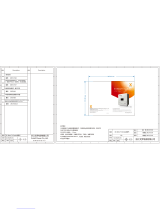
AC10Minute overvoltage Fault.
- System will reconnect if the utility is back to normal.
- Or seek help from us, if can not go back to normal state.
AC10Min Volt Fault
Fault Description
Bus voltage out of normal range.
- Disconnect PV+, PV-, reconnect them.
- Check if the PV input is within the range of the inverter.
- Or seek help from us, if can not go back to normal state.
Over current fault.
- Disconnect PV+, PV-, reconnect them.
- Or seek help from us, if can not go back to normal state.
Else.
- Seek help from us.
Bus Volt Fault
TZ Fault
Other Device Fault
- Disconnect PV+, PV-, reconnect them.
- Or seek help from us, if can not go back to normal state.
Comms Lost