Page is loading ...

- 1 -
(covering the operations with 600T and 600T EN Pressure Transmitter - Rev. up to 5.4, 652/653S Temperature - Rev. 5.1,
Deltapi K Smart Pressure Transmitter - Rev. up to 5.5, KST Temperature - Rev. up to 5.1, Generic HART device - HART 5
Revision, 2600T Pressure Transmitters (models 364, 261, 264, 265, 267, 268, 269), AS 800 Pressure Transmitters, TH02/
TH102/TH202 and TTH300/TTF300 Temperature and Drager Device Polytron IR).
Operating Instruction
IM/691HT_3
Operate
IT
Hand Held Communicator
Model 691HT
INTRINSIC SAFETY VERSION
(Release Firmware 2, Release Software 2.11)

- 2 -
Use of DANGER, WARNING, CAUTION and NOTE
This Pubblication includes DANGER, WARNING, CAUTION and NOTE information where
appropriate to point out safety related or other important information.
DANGER - Hazards which will result in severe personal injury or death.
WARNING - Hazards which could result in personal injury.
CAUTION - Hazards which could result in equipment or property damage.
NOTE - Alerts user to pertinent facts and conditions.
Although DANGER and WARNING hazards are related to personal injury, and CAUTION hazards are
associated with equipment or property damage, it should be understood that operation of damaged equipment
could, under certain operational conditions, result in degraded process system performance leading to personal
injury or death. Therefore comply fully with all DANGER, WARNING and CAUTION.
Health and Safety
To ensure that our products are safe and without risk to health, the following points must be noted:
1. The relevant sections of these instructions must be read carefully before proceeding.
2. Warning labels on containers and packages must be observed.
3. Installation, operation, maintenance and servicing must only be carried out by suitably trained personnel and in accordance with the
information given.
4. Normal safety precautions must be taken to avoid the possibility of an accident occurring when operating in conditions of high
pressure and/or temperature.
5. Chemicals must be stored away from heat, protected from temperature extremes and powders kept dry. Normal safe handling
procedures must be used.
6. When disposing of chemicals ensure that no two chemicals are mixed.
Safety advice concerning the use of the equipment described in this manual or any relevant hazard data sheets (where applicable) may
be obtained from the Company address on the back cover, together with servicing and spares information.
The Company
ABB Automation is an established world force in the design and manufacture
of instrumentation for industrial process control, flow measurement, gas and
liquid analysis and environmental applications.
As a part of ABB, a world leader in process automation technology, we offer
customers application expertise, service and support worldwide.
We are committed to teamwork, high quality manufacturing, advanced
technology and unrivalled service and support.
The quality, accuracy and performance of the Company’s products result from
over 100 years experience, combined with a continuous program of innovative
design and development to incorporate the latest technology.
The NAMAS Calibration Laboratory No. 0255(B) is just one of the ten flow
calibration plants operated by the Company, and is indicative of ABB
Automation’s dedication to quality and accuracy.
BS EN ISO 9001
St Neots, U.K. – Cert. No. Q5907
Stonehouse, U.K. – Cert. No. FM 21106
Stonehouse, U.K. – Cert. No. 0255
UNI EN 29001 (ISO 9001)
Lenno, Italy – Cert. No. 9/90A
ABB AUTOMATION
R
E
G
I
S
T
E
R
E
D
F
I
R
M

- 3 -
The Hand Held Communicator provides a smart
interface with HART electronic transmitters : it is designed
to enable the plant engineer to configure, calibrate and
troubleshoot the transmitters either before or after field
installation.
The Hand Held Communicator can store in its non-volatile
memory up to 32 transmitter configurations.
It can also be used as a Modem between the Personal
Computer and the transmitter.
The Communicator employs a four line by twenty dot-
matrix characters LCD and a 25 key tactile feedback
keyboard : the use of the keyboard is based either on
dedicated keys or software defined keys.
The communication between the Communicator and the
transmitter is based on standard Bell 202 FSK ( Frequen-
cy Shift Keying) current modulation superimposed on the
4 to 20 mA analog signal: since the energy balance
added to the current loop is virtually equal to zero no
disturbance or interference occurs on the analog process
signal.
This version of the Communicator is powered by
internal rechargeable batteries and is certified intrinsi-
cally safe for use in hazardous locations.
CONTENTS GENERAL DESCRIPTION
Section Page
GENERAL DESCRIPTION ............................................ 3
REVISION SUMMARY................................................... 3
COMMUNICATION PROTOCOL ................................... 4
COMMUNICATION APPLICATIONS ............................. 5
KEYBOARD AND DISPLAY .......................................... 7
TRANSMITTER TERMINOLOGY AND
GENERAL OPERATIONS ............................................. 8
GETTING STARTED WITH 691HT HAND
TERMINAL ..................................................................... 9
PASSWORD PROCEDURE ........................................ 10
DIRECT CONNECTION............................................... 11
BROADCASTING CONNECTION ............................... 11
USE OF THE GREEN KEYS - PV -
PROCESS VALUE ....................................................... 12
USE OF THE GREEN KEYS - REVIEW ...................... 13
USE OF THE GREEN KEYS - CONF KEYS ............... 17
USE OF THE GREEN KEYS - TRIM KEYS ................ 31
USE OF THE GREEN KEYS - SERIAL LINK .............. 43
HART RESPONSE MESSAGES ................................. 44
APPENDIX "A1" ........................................................... 50
APPENDIX "A2" ........................................................... 50
APPENDIX "B" ............................................................. 50
APPENDIX "C" ............................................................. 51
APPENDIX "D" ............................................................. 56
TECHNICAL SPECIFICATION .................................... 56
FAULT REPORT SHEET ............................................. 57
REVISION SUMMARY
This is the actual revision of the product: Rev. 3
The actual software version, Rev. 2.11 can be successively updated with the PC Based Program and option LOAD
PROG under SERIAL LINK menu, operation that can be performed at the nearest Service Center.

- 4 -
Since the energy balance added to the current loop
virtually equal to zero and the frequency used for the
communication very high compared to that of the
process dynamic, no disturbance or interference occurs
on the analog process signal.
The Layer 2, the Data Link Layer, provides to form and
check the frame of the messages, accordingly to the
Hart protocol specification. The frame includes a double
parity check, horizontal, at level of each byte transmitted,
and vertical, in form of a parity byte added at the end of
the frame, in order to insure the maximum data integrity.
The figure below gives the structure of a typical frame.
The communication between the Hand Held Communi-
cator and the field devices, like Smart Transmitters, is
based on HART protocol, that permits simultaneous
transmission of the industry-standard 4 to 20 mA analog
signal and of the digital signals carrying the
communication.
The HART protocol follows the OSI ( Open Systems
Interconnection ) reference model proposed by the
ISO ( International Standard Organization ) but uses a
collapsed OSI model implementing only the 1, 2 and 7
layers. The other layers are not necessary for this type
of communication.
The Layer 1, the Physical Layer, physically connects
the devices. It is based on the Bell 202 FSK ( Frequency
Shift Keying ) standard, a ±0.4 mA signal modulation
superimposed on the 4 to 20 mA analog output signal.
The Data Transfer Rate is 1200 Baud. Two frequencies
, 1200 and 2200 Hz, in sinusoidal form, are used to code
respectively the bit "1" and "0. The figure below gives
the modulation envelope respectively for a "1" and a "0"
bit.
Preamble SD AD CD BC RC Data Parity
Contents
Response code
Byte count
Command code
Addresses
Start Delimiter
Preamble ( 5 to 20 "FF" )
The Data Link Layer is also responsible for the
communication between the field devices and the
configurators, either the Hand Held Communicator, a
Secondary Master, or the P.C. Configurator, a Primary
Master and of the issuing of appropriate error messages
in case of communication malfunction.
The Layer 7, the Application Layer is based on the use
of HART Commands, a set of commands sent to a field
device in order to obtain data or information and to
remotely change configuration's parameters.
The Hart Command Set is structured in three classes of
commands:
Universal commands that are implemented and then
recognized by all field devices irrespective of the
manufacturer: the implementation of this class of
commands is mandatory for each manufacturer using
the HART Protocol. This class includes the commands
of reading of the process variable and those of reading
of Universal Information like the Tag, ranges and limits,
date and message,Serial Number,etc.
Common Practice Commands is a class of commands
commonly used by a large number of smart devices :
unlike the Universal Commands their implementation is
not mandatory but the use of this set of commands
increases the compatibility between devices using HART
protocol. This class includes commands to change
common parameters like range values, engineering
units, to perform loop test and so on.
Device-Specific Commands is a class of commands
implemented for a specific device and therefore not
common to other type of equipment. This class includes
the commands related to the specific design of the
device, such as the command for the sensor trimming or
the command to read and interpret the product code,
the sensor materials, etc.
Another small set of commands is reserved for the
manufacturer for use during the manufacturing process.
Any command sent by a Master Device, either the
Primary Master or the Secondary Master, requires a
response message that necessarily includes a Specific
Response Code: the response code gives information
about the correct interpretation and execution of the
received command.
The response code pertains to the Data Link Layer, for
the part concerning the communication, or to the
Application Layer, for the part concerning the application
and in case of errors an error message will be issued: a
specific section of this manual lists the error messages.
+ 0.4 mA
- 0.4 mA
Bit = 1
Bit = 0
f = 1200 Hz
f = 2200 Hz
Level of the
analog signal
COMMUNICATION PROTOCOL

- 5 -
Multidrop connection
The Hand Held Communicator can be connected via its
leads at any point of the current loop : the connection
shall be made in parallel to the multidrop connected-
transmitters, as shown in the figure below, and is
polarity indipendent. Also in this case, a resistor of
250 ohm minimum must be present in the loop,
between the Communicator and the power supply
for communication purpose.
The power supply should provide a minimum voltage of
12 Volt at the transmitters terminals and supply a
current of 4 mA for each transmitter connected. A
maximum of 15 transmitters can be connected in
multidrop mode.
- broadcasting : connection to several transmitters
using a suitable interface that provides a separation
between the analog signals coming from the different
transmitters and the HART digital communication.
Also in this case the access to an individual transmitter
is possible using the TAG. With this type of connection
each transmitter maintains it's analog output and the
full functionality of the transmission loop is maintained.
The operations on transmitters are the same as
indicated for the direct connection.
Broadcasting connection
In the broadcasting configuration the connection can be
made in any point of the common Bell 202 link between
the interface modules and the modem module.
This connection being not directly branched with a low
impedance power supply, no additional resistors are
required.
This manual covers the use of the Hand Held Commu-
nicator in direct, multidrop or broadcasting mode and
gives general information for the use in serial and
modem modes. In these two modes the Communicator
is in slave mode with all the operations performed by the
Personal Computer. The operations that can be
performed using a Personal Computer have still to be
defined. The Software that is going to be adopted will be
probably the SMART VISION! Please refer also to the
Operating Instructions of the Smart ABB pressure and
temperature transmitters for the general and specific
informations on this products.
The Communicator can be used in several different
ways to fullfill the needs of commissioning and mainta-
nance of a HART transmitter:
- direct : the Communicator is directly connected to
the transmitter, either in the field or on the laboratory
bench and the plant engineer may use it to configure,
calibrate or check the connected instrument. Up to 32
different configurations can be saved in the
Communicator memory.
Transmitter direct connection
The Hand Held Communicator can be connected via its
leads at any point of the current loop : the connection
shall be made in parallel to the transmitter and is
polarity independent. Do not connect the Communica-
tor in series in the current loop: this will not damage the
instrument but the current loop will be interrupted.
NOTE - A resistor of 250 ohm minimum must be
present in the loop, between the Communicator and
the power supply for communication purpose.
If the resistor is represented by the intrinsic safety
barrier and the connection is made in the hazardous
area side of the barrier, any possible precaution must
be taken to avoid hazard via the leads or operator.
The insertion or the removal of the Communicator does
not disturb the operation of the loop, whether the instru-
ment is working ( ON ) or not ( OFF ).
- multidrop : the Communicator is multidrop connected
to several transmitters and the access to each
transmitter is possible using the TAG name.
The operation on transmitters are the same indicated
for the direct connection. Note that in multidrop
connection the analog output of each transmitter is
locked to 4 mA and the process value is transmitted
through digital signal.
COMMUNICATOR APPLICATIONS
Power
Supply
≥ 250 Ohm
Control Room Field
691HT
A B C
1
D E F
2
G H I
3
J K L
4
M N O
5
P Q R
6
S T U
7
V W X
8
Y Z #
9
@ % & /
0
+
-
PV
REVIEW
SERIAL
LINK
TRIM
F1 F2 F3 F4
CONF
Bell 202
Modem
Hart Mux I/F
Hart Mux I/F
Hart Mux I/F
to the panel
instruments
To the field mounted Txs
691HT
A B C
1
D E F
2
G H I
3
J K L
4
M N O
5
P Q R
6
S T U
7
V W X
8
Y Z #
9
@ % & /
0
+
-
PV
REVIEW
SERIAL
LINK
TRIM
F1 F2 F3 F4
CONF
Bell 202
Modem
Power
Supply
Up to 15 devices
≥ 250 Ohm
Control Room Field
Output
Current
Fixed at
4 mA
691HT
A B C
1
D E F
2
G H I
3
J K L
4
M N O
5
P Q R
6
S T U
7
V W X
8
Y Z #
9
@ % & /
0
+
-
PV
REVIEW
SERIAL
LINK
TRIM
F1 F2 F3 F4
CONF

- 6 -
FUNCTIONAL DESCRIPTION
The Hand Held Communicator is a microprocessor
based device using a Mitsubishi M377 microcontroller,
a random access memory ( RAM ), a read only memory
(FLASH EEPROM) used for the program, a non-
volatile RAM used to maintain the transmitters
configuration, a Bell 202 Modem, a RS 232 serial
interface, the 4 line by 20 characters liquid cristal
display and a tactile feedback membrane keyboard.
The Hand Held Communicator is powered by a pack of
stilo and rechargeable batteries. The following figure
shows a functional diagram of the Communicator.
- serial link : a RS 232 serial connection provides a
link from the Communicator and a Personal Compu-
ter. This is used for the 691 Firmware upgrade.
Serial connection
DANGER - Do not use the serial connection when in
areas classified as HAZARDOUS LOCATIONS. Such
action could result in FIRE OR EXPLOSION.
The included serial cable should be used to connect the
Communicator to the PC. The cable consists of a 9 pin
male D-sub connector for attaching to the Communica-
tor and a 9 pin female D-sub connector for the PC's
serial port. Also included is a 9 pin to 25 pin serial
adapter wich can be used to adapt the 9 pin end of the
cable to a 25 pin serial port.
The figure below shows the pinout of the 9 pole sub-D
female connector of the Communicator ( view from the
rear of the equipment ).
Modem connection
This connection is made to allow the connection of
transmitters, either in direct mode or multidrop or broad-
casting mode to a Personal Computer using the Com-
municator as a Bell 202 Modem.
The connection from the Communicator and the Perso-
nal Computer is of serial type and therefore make it
using the instructions for the serial link. The connection
between the Communicator and the transmitter/s should
be made using the requested type of connection (direct,
multidrop, broadcasting ).
DANGER: the serial link operation are not allowed in
hazardous area ( area with danger of fire or
explosions).
- modem : the Communicator can be connected to a
Personal Computer Configurator through the serial
link connection and connected to the transmitter,
using the Bell 202 protocol either in direct mode or in
multidrop or broadcasting mode. In the modem mode
the Communicator acts simply as a protocol converter
between the RS 232 and the Bell 202 with all
configuration functions left to the P.C.Configurator.
RS-232
Hart Mux I/F
Hart Mux I/F Hart Mux I/F
P.C. Based software
To the field mounted Txs
691HT
A B C
1
D E F
2
G H I
3
J K L
4
M N O
5
P Q R
6
S T U
7
V W X
8
Y Z #
9
@ % & /
0
+
-
PV
REVIEW
SERIAL
LINK
TRIM
F1 F2 F3 F4
CONF
1 - N.C. ( not connected )
2 - Tx ( Transmit )
3 - Rx ( Receive )
4 - N.C.
5 - Screen
6 - N.C.
7- CTS ( Clear to send )
8 - RTS ( Ready to send )
9 - N.C.
5 1
9 6
DISPLAY KEYBOARD MICROCONTROLLER RAM
to the P.C.
BUS
any point
in the loop
691HT Functional Block Diagram
MODEM FLASH EEPROM NON-VOLATILE EEPROM RS 232
STILO OR RECHARGEABLE
BATTERY PACK

- 7 -
Monitor the process variables and output
current values of the transmitter. The Com-
municator continuously updates the display
with this information approximately twice per
second. Additional functions available through
the use of this key may, depending on the
transmitter, include monitoring the sensor
temperature or static pressure.
Review the connected transmitter's databa-
se. This information includes: output para-
meters; revision info; other miscellaneous
info. Use of this key does not give the user the
ability to change any information. To make
changes the user must use the CONF key.
Configure or edit the transmitter's database.
The user is allowed to specify output parame-
ters, identification info and material info. In
addition the user may perform operations
involving transmitter database such as li-
sting, saving, downloading and deleting.
KEYBOARD AND DISPLAY
The display is a 4 line by 20 characters liquid cristal
display mounted at an angle to the face of the Commu-
nicator to increase readability. The first two lines of the
display are dedicated to data or messages for the user.
The botton two lines of the display are used for labelling
the function keys, as shown in the figure below.
The keyboard is comprised of 25 keys arranged in 3
functional groups.
Located below the LCD display is a group of 4 program-
mable function keys ("softkeys") labelled F1 - F4. The
definition of these keys varies based on the operation
the user is trying to perform. The function of each key is
defined by the corresponding label displayed by the
LCD above.
At the bottom of the Communicator there is a group of
12 keys used for the entry of numeric data and letters,
along with a decimal point ( . ) and a change sign, i.e.
( +/- ) keys.
There is a group of nine dedicated function keys
located on the face of the Communicator. Two keys are
dedicated to turning the Communicator ON or OFF.
Two other keys assist in keyboard entry ( ENTER ) and
returning to the previous menu ( ESCAPE ). The
remaining keys in the group are associated with
transmitter functions. A more detailed description of the
dedicated keys is presented below.
DIR BRD TX PASS
ECT CAST DIR WORD
MAIN MENU
PV
REVIEW
CONF
NOTE : The Communicator automatically shut off in
order to conserve battery power, if it senses that the
unit has not been used for 9 minutes. This feature is
disabled when the PV function is currently in use,
when the Communicator is in DATA BASE MODE, in
MODEM MODE or during firmware and software
upgrade, i.e. when in LOAD PROG Mode.
LINK
SERIAL
Configure the Communicator as a Modem or
to upgrade it.
Perform trimming of the sensor or output
circuitry and reranging the sensor.
Confirm data entry during input operations.
This key is sometime super seded by function
key F4 which often serves as ENTER also.
Abort the present operation or return to the
next higher ( previous ) menu screen.
Switch ON the Communicator ( OFF is
for switch off) .
TRIM
F1 F2 F3 F4
691HT
A B C
1
D E F
2
G H I
3
J K L
4
M N O
5
P Q R
6
S T U
7
V W X
8
Y Z #
9
@ %
& /
0
+
-
SERIAL
LINK
F1 F2 F3 F4
PV
TRIM
REVIEW
CONF

- 8 -
TRANSMITTER TERMINOLOGY
The Communicator primary use is the commissioning
and the servicing of Smart transmitters. The commis-
sioning includes all the operation of functional testing of
the transmitter and check of the transmitter configura-
tion data normally performed before the putting in service,
while the servicing is for operation after installation.
Commissioning can be done either in the field or on the
bench.
The advent of smart microcontroller-based transmitters
brings new procedure and terminology to the instru-
mentation field, not present in the days of pure analog
transmitters. This manual would like to present the
following terminology to define some of the operations
of commissioning as follows:
- Ranging - Setting either or both the lower and upper
value ( LRV & URV ) thereby determining the zero and
span by user entry of the numeric values. This operation
is available to the user via the CONFiguration menu.
Also called "Dry Calibration".
- Reranging - Setting either or both the lover and upper
range values ( LRV & URV ) using the value of the
applied pressure or input reference. This operation
requires accurate test equipment. This operation is
available to the user via the RERANGING function
under the TRIMming menu. Also called "Wet calibration".
- Trimming - Performs small corrections to either the
sensor measurement value or the analog output value
( i.e. corrections to either the input or output sides of the
transmitter's microcontroller ). Major detail on this ope-
ration can be found in the "Use of the green keys-TRIM"
section of this manual. This operation requires accurate
test equipment. This operation is available to the user
via the SENSOR TRIM and the 4-20 mA TRIM under the
TRIM menu.
Consideration on accuracy
The use of a sensor having a good intrinsic linearity and
repeatability and the possibility to compensate, using a
microprocessor, the residual non linearity errors and the
errors due to the influence of the temperature and static
pressure leads to an instrument having a very high
accuracy.
The factory final calibration of the transmitter is done
using testing equipment having an accuracy from four
to ten times the specified accuracy of the transmitter.
This facts bring to the consideration that, unless your
testing equipment is of a suitable class ( accuracy three
times of the transmitter accuracy ), a calibration done
using the Ranging procedure leads to results that are
surely better that a calibration done using poor quality
testing equipment.
Before to decide about the type of calibration to perform
it is then to check the transmitter accuracy stated in the
specification sheet and the accuracy of the testing
equipments available.
GENERAL OPERATIONS
Battery Charging
There are four nickel-cadmium rechargeable batteries:
the expected working time of the Communicator with
the battery full charged is about 10 hours. When the
battery is nearly 90% gone, i.e. 1 working hour is still
available, a low battery warning signal, (
L
B ) is displayed
in the lower right corner of the LCD display.
The Non-Volatile EEPROM ( which is used to store
database configurations ) is not affected by a low
battery voltage or battery replacement.
The battery pack has an expected life of 1000 charge/
discharge cycles. This expectancy is valid if the charge/
discharge cycles are properly performed. Nickel-cad-
mium batteries require that they are nearly fully dischar-
ged before recharging, therefore the user should wait
for the low battery indication before recharging.
DANGER - Do not use the battery charger in areas
classified as HAZARDOUS LOCATIONS. This can
results in HAZARD OF FIRE AND EXPLOSIONS.
The battery charging should be done using the battery
charger optionally supplied with the Communicator.
Use of other chargers is discouraged but can be used.
Under such conditions, it should be noted that the
maximum charging current be less than 50 mA. If a
constant voltage charger is used the voltage must be
7.5 Volt D.C. The full charge of the battery pack requires
about 12/15 hours.
Access to the battery charging connector is by removal
of the cover plate located at the top of the Communica-
tor. The connector is a 5.5 mm plug with the center
contact being positive (+) and the outside contact being
nagative (-).
CAUTION - Do not maintain the battery charger
connected for more than 15 hours: the battery pack
and the internal circuit may be damaged.
Battery pack replacement
The battery pack consists in a plastic box containing the
Ni-Cd battery and all the necessary intrinsic safety
protection diodes and resistors. The plastic enclosure
is completely filled with silicon resin to prohibit access
to the components.
DANGER : Do not remove the silicon resin
protection, don't change or modify intrinsic safety
components. This can cause HAZARD OF FIRE
AND EXPLOSIONS.

- 9 -
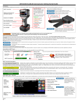
GETTING STARTED WITH 691HT HAND TERMINAL
Connect the Communicator with the transmitter following the instruction
in the relevant chapter of this manual and then press the ON key.
The ON key must be kept pressed for one second. The first display at side
appears for some seconds, giving indications on the 691HT revisions and
language.
After some seconds the Main Menu appears on the screen giving the
access to the main procedure:
Direct and Broadcast : to initialize the communication with a transmitter.
Password : to insert or change the password to protect the access to
some operations, namely Conf, Trim, Serial Link and Password itself.
Tx Directory: to visualize (scrolling) the list of device that one configurable
using the installed software revision.
Example of Transmitter Directory:
GENERIC HART 1.2
TH02 Temperature 1.1
AS800 Pressure 1.1
Deltapi K Pressure 1.0
600T Pressure 1.1
600T EN Pressure 1.1
600T/2600T SAFE
2600T Pressure
MAIN MENU
DIR BRD TX PASS
ECT CAST DIR WORD
ABB SACE
Firmware Rev. 2
Software Rev. 2.11
Language: ENGLISH
Transm. Directory
_ _ _ _ (List of HART devices
_ _ _ _ _ _ supported) _ _ _ _
_ _ _ _ _ _ _ _ _ _ _ _ _ _ _ _ _
- the transmitter connection consists of a double bana-
na jack suitable for a double banana plug patch cord.
- the serial link ( RS 232 ) connection consists in a std.
Type D subminiature 9-pole female connector.
- the battery charger connection consists in a 5.5 mm.
round socket.
The two latter are protected by a plastic cover that can
be removed unscrewing a Allen screw.
DANGER - Do not remove the cover or use the unit
with the cover removed in area classified as HA-
ZARDOUS LOCATIONS: THIS CAN RESULT IN
HAZARD OF FIRE AND EXPLOSIONS.
Banana plug for
transmitter conn.
Battery
charger
conn.
RS 232 Serial
connection
For battery pack replacement proceed as follows:
- Unscrew the two Philips screws and remove the batte-
ry pack. Unplug the battery cable connector.
- Plug the battery cable connector in the new battery
pack and fit it in the battery recess, paying attention
that the cable is properly fitted. Fix it with its screws.
- Switch on the unit and check if the battery low warning
appears. In case that doesn't appears discharge the
battery until it appears.
- Charge the battery for 12/15 hours.
NOTE - Since the Battery Pack is intrinsically safe it
is possible to replace it in a hazardous area. Howe-
ver this is not recommended as good standard
practice.
ELECTRICAL CONNECTIONS
All the electrical connections are grouped in the rear
part of the Communicator and include the following
( see figure below ):

- 10 -
PASSWORD PROCEDURE
If you want to enable the password or to change the existing one press
the F4 function key, corresponding to the label PASSWORD in the main
menu. The password menu will appear. The possible password operation
are the following:
- setting a password and enabling it.
- changing an existing password and enabling it
- disabling a password
Setting a password. If you want to set a password press the function
key F1, labelled ENABLE: If the password is already enabled, then a new
display, shown below, gives the possibility to change the existing
password or to proceed without changing it. Otherwise, pressing F1,
appears the following:
Insert the numeric password: it can be any number from 1 to 6 digits.
If a mistake is made, the CLR key should be pressed to start again.
After entry as been completed pressing the ENTeR key a new display
appears asking to repeat the entry for security reasons.
Pressing the ENTeR key the next screen appears confirming that the
password has been successfully entered and enabled: if for some
reason the procedure aborts then the following message is displayed:
"Password incorrect - Press any key to continue "
In both cases, pressing any key you will return to the Password Main
Menu: then press ESCape if you wish to leave the password procedure.
NOTE - Be extremely careful not to forget an entered password, as
the user has no way of circumventing the security feature.
Changing an existing password. If a password exists and is enabled,
the following screen will appear when the F1 key, corresponding to
enable, is pressed. Pressing the F4 key you will return to the Password
Main Menu while pressing F1 to CHaNGe the following display appears.
Input the existing password. If the password is not correct then the
following message is displayed: "Password incorrect - Press any key
to continue ". Pressing any key you will return to the Password Main
Menu.
If the password is accepted then the next screen appears: insert the new
numeric password. If a mistake is made, the CLR key should be pressed
to start again. After entry has been completed pressing the ENTeR key
a new display appears asking to repeat the entry for security reasons.
Pressing the ENTeR key a screen appears confirming that the password
has been successfully entered and enabled: if for some reason the
procedure abort then the following message is displayed:
"Password incorrect - Press any key to continue "
In both the case, pressing any key you will return to the Password Main
Menu: then press ESCape if you wish to leave the password procedure.
Password disable . If you select, from the Password Main Menu, the
DISABLE option, then the following screen is presented: insert the
existing numeric password and then press F4 to ENTeR.
The following message is displayed: " Password disabled - Press any
key to continue".
Note - If you have unlackely forgotten the Password, please contact your
nearest ABB Instrumentation Service Center.
If the password is already disabled or some mistake is made inputting
the password, one of the following messages will be displayed:
" Password already disabled - Press any key to continue "
" Password incorrect - Press any key to continue ".
In both cases, pressing any key you will return to the Password Main
Menu: then press ESCape if you wish to leave the password procedure.
P A S S W O R D
E N A D I S A
B L E B L E
I n p u t n u m e r i c
p a s s w o r d :
[ _ _ _ _ _ _ _ ]
CL R E N T R
R e t y p e p a s s w o r d :
[ _ _ __ _ _ _ ]
C L R E N T R
P a s s w o r d e n a b l e d
P re s s a n y k e y t o
c o n t i n u e
P a s s w o r d a l r e a d y
e n a b l e d
C H N G P R O
C E E D
I n p u t e x i s t i n g
p a s s w o r d :
[ _ _ _ _ _ _ ]
CL R E N T R
I n p u t n e w
p a s s w o r d :
[ _ _ _ _ _ _ ]
CL R E N T R
R e t y p e n e w
p a s s w o r d :
[ _ _ _ _ _ _ ]
C L R E N T R
I n p u t e x i s t i n g
p a s s w o r d :
[ _ _ _ _ _ _ ]
CL R E N T R

- 11 -
T X : 600T Press ( +EN )
T A G : X X X X X X X X
SELECT GREEN KEY
X M T R N O T I N
C O M M U N I C A T I O N
RETRY
POLL
P o l l i n g A d d r e s s : (0 3 )
P R O
C E E D
MAIN MENU
DIR BRD TX PASS
ECT CAST DIR WORD
DIRECT CONNECTION
Supposing that a direct connection to the transmitter has been done,
press the function key F1, corresponding to the label "direct", to establish
the communication with the transmitter. In the top right angle of the display
will appear a symbol, like a T, signalling that the communication is on
course and, after some seconds, a new display appears. Some Warning
messages can appear : please refer to the Error and Warning Message
Section. Press any key if requested.
The transmitter's type, Pressure or Temperature and the TAG are
displayed. If the Tag is not yet defined the space after the semicolon will
be blank (for other manufacturers' Tx only TAG is displayed). Now,using
one of the green keys, you can select one procedure: the use of the green
keys will be discussed later on.
In case that the communication does not take place the display at the side
will appear: the F1 key allows you to RETRY checking if the transmitter
has a polling address different than zero, i.e. is set for multidrop connec-
tion. In this case the following display will appear.
The display shows, within square brackets, the polling address of the
connected transmitter. Pressing F4 to PROCEED the display showing
the TAG and the TX type and the label SELECT GREEN KEY appears.
Before TAG and TX type an additional message:
WARNING: Output Current Fixed
is used to indicate that the analog output signal, in case of polling address
different than zero, remains fixed at 4 mA value.
See Section in CONF for Polling Address Setting and disabling.
BROADCASTING CONNECTION
If transmitters are connected in broadcast mode press the function key F2
in the Main Menu, corresponding to the label "BRD-CAST" and the display
will change as follows.
To access a transmitter you can use the TAG name.
If a tag has already been written in the transmitter two methods of access
can be used depending if the Tag is included in the Communicator
Database or not included. In the first case, pressing F2 (TAG SEL) in the
Access Method Menu, the tags stored in the Communicator are displayed,
four per display, at a rate of 3 seconds: using F1 you can stop the listing
whereas with F2 or F3 you can move forward or backward in the list. When
the required tag is on the display, you can select it moving, using F4, the
cursor on it: now pressing the ENTER key you make the selection.
The second method of access is via TAG ENTER; in this case the
following display appears. Use the key board to input character and the
key F1 and F2 to move the cursor. The key F3 can be used to clear the
tag name on the screen.
When, using one of the methods, the tagname has been composed press
ENTER to establish the communication with the selected transmitter.
In the top right angle of the display will appear a symbol, like a T, signalling
that the communication is on course and, after some seconds, the display
at side appears. If Warning Messages are displayed, please refer to Error
and Warning Message Section for details. Press any key if requested.
ACCESS METHOD
TAG T A G
ENTR S E L
F T 1 00 L T 1 1 2
P T 2 3 4 F T 2 5 6
S T O P N E X T L A S T S E L
L I S T P A G E P A G E T A G
E N T E R T A G
< - - - - > CLR ENTR
MAIN MENU
DIR BRD TX PASS
ECT CAST DIR WORD
T X : 600T P r e s s. (+EN)
T A G : FTD - 200
SELECT GREEN KEY

- 12 -
USE OF THE GREEN KEYS - PV - PROCESS VALUE
The green key PV ( Process Value ) allows the user to monitor the process
value and the current output of the transmitter. The process value appears
in user configured engineering units while the output current is in
milliamps.
Monitoring of other transmitter measured value is possible by the use of
labelled function keys and is different depending on the transmitter type:
the first three displays are related to pressure transmitters while the
remaining are for temperature transmitters.
The indication "NOT PROCESS TEMP" reminds that the displayed
temperature cannot be considered as the process temperature being the
temperature reads in the sensor's core.
For the temperature transmitters the initial display shows the process
value in the user configured engineering units and the output value in
milliamps. The secondary displays change depending upon the type of
the sensor element ( thermocouple, resistance thermometer, variable
resistor or mV generator ) and single or differential measurement.
For thermocouple and mV measurement pressing the F1 key the CJC
temperature is displayed ( as shown ), while for other types of measure-
ment the electronics internal temperature is displayed.
The F2 and F3 keys can be used only for differential measurement to
display the measured value of the two sensors expressed in the same
units than the process value. If used for other types of measurement an
error message will be displayed: VALID ONLY FOR DIFFERENTIAL T/C.
If the Communicator is connected with a generic smart HART transmitter
the PV green key will operate in a similar way to display the process variables
in the following order:
PV: for primary variable
OUTPUT: for analog output current
F1, F2 and F3 are used respectively to display secondary (SV), tertiary (TV)
and fouth (QV) variables.
P V : 1 2 3 4 . 5 6 m b a r T
O U T P U T : 1 2 . 3 4 m A
S T AT S N S R
P R E S T E M P
S T A T I C : 1 . 2 3 4 T
M P a
S T E M P : 2 3 . 4 T
D e g . C
N O T P R O C E S S T E M P
For Temperature Transmitters
P V : 1 2 3 .4 5 D e g. C T
O U T P U T : 1 2 . 3 4 m A
TEMP SNSR SNSR
ERAT 1 2
CJC Temperature :
2 0 . 5 D e g . C
For 600T, 600T EN and Deltapi K
Pressure Transmitters
P V : 1 2 3 .4 5 D e g. C T
O U T P U T : 1 2 . 3 4 m A
SV TV QV
For Generic HART device

- 13 -
USE OF THE GREEN KEYS - REVIEW
The dedicated function key REVIEW allows the user to view the transmitters
configuration data. The information contained under Tx Info varies slightly
depending on transmitter type. See below the relevant information for
600T and 600T EN Pressure and for 652/653S Temperature transmitters.
Each parameter of a section is normally displayed at a rate of approxima-
tely 2 seconds. The listing of the parameter may be stopped (F1 - STOP
LIST), started again (F2 - STRT LIST), advanced (F3 - NEXT ITEM) or
backed-up (F4 - LAST ITEM).
The information for Deltapi K and KST Tx are described next in this
section.
R E V I E W
T X
I NFO
U N I T S : m b a r
STOP STRT NEXT LAST
L I ST L I ST ITEM ITEM
Information displayed under TX INFO common
for all HART transmitters
TX : Model type of transmitter.
BY : Manufacturer of transmitter.
TAG : Tag name identifier of unit.
DESCRIPTOR : The transmitter service.
MSG : A message that can be written, using the P.C.
Configurator, for warning or maintenance use.
DATE : User specifiable date. May be used to log the
installation, calibration or last servicing date.
DEV NUM : Factory assigned electronics serial number.
UNITS : Engineering units for reporting process value
or entering range values.
LRV : Lower Range Value. The lowest value that the
transmitter is adjusted to measure. Also known as the
zero or 4 mA point.
URV : Upper Range Value. The highest value that the
transmitter is adjusted to measure. Also known as the
full span or 20 mA point.
DAMPING : The time constant, in seconds, of a first
order filter applied to the input.
OUTPUT : Type of the transfer function applied to the
input to obtain the output. Linear, Square root and
Polynomial for 600T Tx (not for temperature transmitter).
LIMS UNITS : Units used to express the sensor's
calibration limits.
MIN SPAN : The minimum allowed value for the span.
The span is the algebraic difference between the Upper
and Lower Range Values.
LRL : Lower Sensor Limit. The lowest value of the
measured value that the transmitter can be adjusted to
measure.
URL : Upper Sensor Limit. The highest value of the
measured value that the transmitter can be adjusted to
measure.
FINAL ASSY NUMBER: the transmitter final assembly
serial number.
P V SENSOR S/N : The sensor's module serial number
(not for temperature transmitter)
H / W : Electronics hardware revision level
S / W : Electronics software revision level
U C D : HART Universal Command document revision
level which the HART protocol was implemented
T S D : Transmitters Specific document revision level
For both 600T and 600T EN pressure transmitter
MAX WORKING PRES. with its units :
The maximum pressure to which the transmitter can be
submitted without causing danger and damage.
MAX SENSOR TEMP. with its units :
The maximum temperature to which the transmitter's
sensor can be submitted without damage.
MIN SENSOR TEMP. with its units :
The minimum temperature to which the transmitter's
sensor can be submitted without damage
.
ROOT XFER FUNCTION: (not for 600T EN)
The output variation from 0% to 20% of the output, when
the SQR(x) output transfer function is selected.

- 14 -
UP/DOWN SCALE :
the value to which the output is
forced when a major fault occurs.
POLY COEFF. A0 (to A5) :
The coefficients of the
polynomial (in scientific notation and not for KSx)
FLANGE TYPE : The flange type
FLANGE MATERIAL : The flange material
O-RINGS : The material of the O-Rings
VENTS : The vents material
NUMBER OF REM.SEAL: the number of remote seal
REMOTE SEAL TYPE : The type of remote seal.
REMOTE SEAL FILL. : The remote seal filling liquid.
REM.SEAL ISOLATOR : The material of the remote
seal wetted diaphragm.
SENSOR FILL.FLUID : The filling fluid of the sensor.
SENSOR ISOL.MTL.: The diaphragm sensor's material.
MODEL TYPE : The transmitter model.
SENSOR RANGE : The sensor's range.
LOCAL ADJUSTMENT: Wheter the instrument is fitted
with Zero and/or Span calibration buttons or not.
LOCAL KEYS CONTROL: The local adjustments are
enabled or disabled
LCD DISPLAY MODE:
The variables displayed by the
LCD integral display.
H / W WRITE PROT. : Whether the configuration is
protected by the hardware jumper or not.
METER INST. : Whether the integral meter is installed
or not.
CALIBRATION TYPE : Standard or specific on operating
pressure or temperature or both.
PROCEDURE TYPE : Type of any special procedure
required for the manufacture of the sensor.
PRODUCT CODE : Transmitter's product code.
SEP. &/OR SERVICES : Code of remote seal or code
for special services or calibration.
MANIFOLD OR ORIFICE : Code of manifold or integral
orifice.
and in addition for 600T EN pressure transmitter
LONG TAG : Process or Plant identifier with a maximum
length of 24 characters.
PV BIAS VALUE : Value that can be applied to the
primary variable for scaling. It is stated in the same unit
of the primary variable.
SQR (x) CUT LINEAR : The connection point between
the linear line and square root line (from 10% to 20%).
OPERATIVE LRL : Low operative limit when PV BIAS
is active (when PV BIAS VALUE not equal to 0).
OPERATIVE URL : High operative limit when PV BIAS
is active (when PV BIAS VALUE not equal to 0).
DOUBLE POLY B0(to B2) - C0(to C2): The coefficients
of the double polynomial function (in scientific notation).
1ST POLY HIGH LIM. : Output percentage that identifies
the connection between the 1st and the 2nd polynomial
function of the Double Polynomial function.
and in addition for 652/653 S Temperature
METER OPTION : identifies if the transmitter is provided
with output meter (LCD or analog).
SENSOR TYPE : the type of the sensor element:
millivolt, thermocouple, resistance thermometer, ohms.
MEASUREMENT TYPE : single or diff. measurement.
CJC TEMPERATURE: constant cold junction
compensation value (-40°C to +135°C)
MULTIPLICAT. FACT: Multiplication factor for 100Ω
RTDs.
MAX TEMP FOR SENS.: Maximum temperature on
individual sensors for differential measurement.
TOTAL RESIST (Ohm) : Total cable resistance value.
CERTIFICATION TYPE : General purpose, intrinsic
safety, flame proof.
mA 100%: Output current at 100% range value.
mA 0% : Output current at 0% range value.
mA HLim : Output current upper limit.
Max: Maximum measured value
Min: Minimum measured value
mA LLim : Output current lower limit
SENSOR ERROR CONF. : Sensor error configuration.
SHORT V : Output current for short-circuited sensor.
OFF VAL : Output current for broken sensor.
TRANSMITTER VERSION : the version type of the
transmitter, 652S or 653S, head or integral mounted.
DIS (TRIBUTOR) : The name of the distributor.

- 15 -
Here follows the information for Deltapi K Pressure and KST Temperature under Review green key.
U N I T S : m b a r
STOP STRT NEXT LAST
L I ST L I ST ITEM ITEM
USE OF THE GREEN KEYS - REVIEW
Using the green dedicated function key REVIEW allows the user to view
different sections of the transmitters configuration. The Review Menu
varies slightly depending on transmitter type: the top display is pertinent
to the Deltapi K pressure transmitter while the partially hidden display
is for KST temperature transmitter. The F4 key, NEXT OPTN, in the
pressure transmitter Review Menu gives the access to a second menu
Review screen: the ESCAPE key allows to come back to the previous
menu.
Each parameter of a section is normally displayed at a rate of approxima-
tely 2 seconds. The listing of the parameter may be stopped ( F1 ), started
again ( F2 ), advanced ( F3 ) or backed-up ( F4 ).
The following tables describes the parameters presented under each
review section. Some parameters are available only for a type of transmit-
ter: a note gives this information.
Information displayed under TX INFO
TX : Model type of transmitter.
BY : Manufacturer of transmitter.
TAG : Tag name identifier of unit.
DESCRIPTOR : The transmitter service.
MSG : A message that can be written, using the P.C:
Configurator, for warning or maintainance use.
DATE : User specifiable date. May be used to log the
installation, calibration or last servicing date.
DEV NUM : Factory assigned electronics serial number.
MAX WORKING PRES. with its units :
( Pressure only)
The maximum pressure to which the transmitter can be
submitted without causing danger and damage.
METER OPTION:
(KST Temperature only)
identifies if
the transmitter is provided with output (LCD or analog)
meter.
Information displayed under REVISION
H / W : Electronics hardware revision level
S / W : Electronics software revision level
U C D : HART Universal Command document revision
level which the HART protocol was implemented
T S D : Transmitters Specific document revision level
Information displayed under OUTPUT
UNITS : Engineering units for reporting process value
or entering range values.
LRV : Lower Range Value. The lowest value that the
transmitter is adjusted to measure. Also known as the
zero or 4 mA point.
URV : Upper Range Value. The highest value that the
transmitter is adjusted to measure. Also known as the
full span or 20 mA point.
DAMPING : The time constant, in seconds, of a first
order filter applied to the input.
OUTPUT :
( Deltapi K Pressure only )
Type of the
transfer function applied to the input to obtain the output:
linear or square root.
LIMS UNITS : Units used to express the sensor's
calibration limits.
MIN SPAN : The minimum allovable value for the span.
The span is the algebraic difference between the Upper
and Lower Range Values.
LRL : Lower Sensor Limit. The lowest value of the
measured value that the transmitter can be adjusted to
measure.
URL : Upper Sensor Limit. The highest value of the
measured value that the transmitter can be adjusted to
measure.
UP/DOWN SCALE :
(Deltapi K Pressure only)
the value
to which the output is forced when a major fault occurs.
OUT T X R E V I P R O D
PU T I NFO S I O N D A T A
R E V I E W
OUT T X MATE N E X T
PU T I NFO R I A L O P T N

- 16 -
Information displayed under MATERIAL
( for Deltapi K pressure type only )
FLANGE TYPE : The flange type
FLANGE MATERIAL : The flange material
O-RINGS : The material of the O-Rings
VENTS : The vents material
NUMBER OF REM.SEAL: the number of remote seal
REMOTE SEAL TYPE : The type of remote seal.
REMOTE SEAL FILL. : the remote seal filling liquid.
REM.SEAL ISOLATOR : The material of the remote
seal wetted diaphragm.
SENSOR FILL.FLUID : The filling fluid of the sensor.
SENSOR ISOL.MTL.: The diaphragm sensor's material.
MODEL TYPE : The transmitter model.
SENSOR RANGE : The sensor's range.
NUTS AND BOLTS :
The material of the nuts and bolts.
.
PUSH BUTTONS: Wheter the instrument is fitted with
Zero and/or Span calibration buttons.
Information displayed under PRODuct DATA
( for KST Temperature Type only )
SENSOR TYPE : the type of the sensor element: millivolt,
thermocouple, resistance thermometer, ohms.
NUMBER OF WIRES : Two, three or four
LINEARIZATION MODE : linear with input or with
temperature.
MEASUREMENT TYPE : single or diff. measurement.
EXISTING TRIM : user, or factory calibration
UPPER TRIM POINT : the value of the upper trim point.
LOWER TRIM POINT : the value of the lower trim point.
TRIM POINT UNITS : the units used for the above
parameters.
CERTIFICATION TYPE : General purpose, intrinsic
safety, flame proof.
CONN. HEAD LENGTH : The length of the connection
head's extension.
BROKEN SENSOR DRIVE : Output driven >20 mA or
<4 mA if the sensor or the sensor connection breaks.
CAL. CERTIFICATE : Provided or not.
PUSH BUTTONS : Installed or not installed.
PRODUCT CODE : The transmitter's code number.
H/W WRITE PROT. Whether the configuration is
protected by the hardware straps.
FINAL ASSY NUMBER : the transmitter's final assembly
serial number.
Information displayed under MISCELLaneous
( for Deltapi K pressure transmitter only )
FINAL ASSY NUMBER : The transmitter's final assembly
serial number
P V SENSOR S/N : The sensor's module serial number
H / W WRITE PROT. : Whether the configuration is
protected by the hardware jumper.
METER INST. : Whether the integral meter is installed.
CALIBRATION TYPE : If std. or specific on operating
pressure or temperature or both
PROCEDURE TYPE : Type of any special procedure
required for the manufacture of the sensor.
PRODUCT CODE: Code of the Transmitter
SEP. &/OR SERVICES : Code of remote seal or code
for special services or calibration
MANIFOLD OR ORIFICE : Code of man. or int. orifice.

- 17 -
Change I/O Parameters:
Engineering Units
Lower/Upper Range Value
Damping Time Constant
Output Function
Database Memory Oper.
Tag List
Save Configuration
Send Configuration
Delete Configuration
Tx Information (XMTR INFO)
Tag Name
Date
General Configuration
Polling address
Change I/O Parameters:
Engineering Units
Lower/Upper Range Value
Damping Time Constant
Output Function
Root Transfer Function
(600T only)
SQR(x) cut linear
(600T EN only)
Poly Coefficients
Double Poly Coefficients
(600T EN only)
Sensor Temperature Units
Static Pressure Units
Long Tag (600T EN only)
Database Memory Oper.
Tag List
Save Configuration
Send Configuration
Delete Configuration
Tx Information (XMTR INFO)
Tag Name
Date
General Configuration
Polling address
Local Keys Mode
LCD Display Mode
For generic HART Transmitter of other manufacturers
USE OF THE GREEN KEY - CONF KEY
Transmitter parameters which are user configurable may be changed by the use of the Configuration Menu
accessible via the CONFiguration dedicated function key. These items are organized into Submenus, as follows:
For 600T and 600T EN Pressure Transmitter
Change I/O Parameters:
Engineering Units
Lower/Upper Range Value
Damping Time Constant
Output Function
Database Memory Oper.
Tag List
Save Configuration
Send Configuration
Delete Configuration
Tx Information (XMTR INFO)
Tag Name
Date
General Configuration
Polling address
Up/Down scale
For Deltapi K Pressure Transmitter
Change I/O Parameters:
Sensor Type
Engineering Units
Lower/Upper Range Value
Damping Time Constant
Database Memory Oper.
Tag List
Save Configuration
Send Configuration
Delete Configuration
Tx Information (XMTR INFO)
Tag Name
Date
General Configuration
Polling address
For KST Temperature Transmitter
Change I/O Parameters:
Sensor Type
Engineering Units
Lower/Upper Range Value
Damping Time Constant
mA100%
mA 0%
Total Resist (Ohm)
Short Val
Off Value
Max
Min
Database Memory Oper.
Tag List
Save Configuration
Send Configuration
Delete Configuration
Tx Information (XMTR INFO)
Tag Name
Date
General Configuration
Polling address
For 652/653 S Temperature Transmitter

- 18 -
I n p u t n u m e r i c
p a s s w o r d :
( . . . . . . . . . . )
C L R E N T R
CONFIGURATION
CHNG XMTR GEN DBASE
I / O I NFO CONF MEM
P a s s w o r d i n c o r r e c t
P R O
C E E D
Use of the Green Key - Access to the CONF procedure
The access to the CONF procedure, as well as the TRIM and the
SER.LINK, can be protected by the use of a Password: if this option has
been enabled then the following display will appears when the CONF
green key will be pressed .
Insert the numeric password using the numeric keys and the function key
labelled ENTER. If the password is correct the unit will proceed to the main
menu screen. Otherwise a warning message is displayed and the user is
allowed to re-attempt entry. If the user makes a mistakes during entry, the
CLR key may be used to erase the input and start over.
The access to the above mentioned procedure remains possible until the
unit is switched off. If the password is disabled then the access is
immediate and the Main Menu screen is suddendly displayed.
CONF - XMTR INFOrmation - TAG and DATE options
Using the CONF key, when the display with the message " SELECT
GREEN KEY" is present, the following display will appear:
Pressing F2, corresponding to "XMTR- INFO" (Transmitter Information )
you access the procedure of changing some information, these are the
TAG and the DATE: usually the TAG changing option is displayed: if a Tag
was already assigned to the transmitter, then it will appear on the display.
Using the F3 key, corresponding to CHaNGe, the next display will appear:
Use key F1, F2 and F3 together with the keyboard (letters and numbers)
to input characters. Up to eight characters can be used to form the
tagname: the key CLR deletes the name inserted. When the full tagname
has been composed press ENTER to establish the communication with
the selected transmitter and store the new tag.
T A G : O L D T A G
N E X T L A S T CHNG
O P T N O P T N
T A G : [ N E W T A G ]
< - - - - > C L R E N T R
T A G : N E W T A G
N E X T L A S T CHNG
O P T N O P T N
D A T E : DD / MM / YY
1 1 / 1 1 / 0 0
N E X T L A S T CHNG
O P T N O P T N
After some seconds the new display appears and, as you can see, the
new TAGname ( as an example NEWTAG ) has been included in the
display and in the transmitter's configuration. Use the key ESCAPE to
return to the previous display/s. Using the F1 key ( NEXT OPTioN ) it is
possible to select the Date changing procedure and the following display
will appear.
Using the F3 key, corresponding to CHaNGe, the next display will appear
with a blinking cursor visible in the date area.Using the numeric keypad
it is possible to change the digit pointed by the cursor. The cursor shifts
automatically after each entry. In case of error shift backward using the
F1 key and digit the correct number. When the complete date is
composed press the F4, corresponding to " ENTeR" to establish the
communication with the selected transmitter. After some seconds, a new
display appears with the updated date. Using the ESCAPE key you can
return to the previous display/s.
D A T E : DD / MM / YY
[ 0 1 / 0 1 / 0 1 ]
<- - - - > E N T R
D A T E : DD / MM / YY
0 1 / 0 1 / 0 1
N E X T L A S T CHNG
O P T N O P T N

- 19 -
Unlike the pressure transmitter where the sensor is part of the instrument,
the temperature transmitter can be supplied either complete with his
sensor ( thermocouple or RTD ) or without it. It can then be necessary to
configure the transmitter accordingly to the type of sensor and of
measurement, single or differential, that will be used.
Using the F1 key select the CHaNGe I/O procedure: the following display
will appear. Pressing F1 or F2 you can select the next or the last otion of
this procedure.
If you wish to change the type of sensor press the F3 key ( CHNG): the
screen will display a warning message: " WARNING - Control loop
should be in manual". Press the PROCEED key to acknowledge the
message and continue.
The previous screen is newly displayed with the sensor type within square
brackets: using the F1, for next otion, or F2, for last option, you can select
the sensor type (see the list of the available choice in the next page) you
wish to connect to your transmitter. Press F4 to confirm your selection.
The next screen gives the selection of the type of measurement, i.e. if
single or differential: you can confirm the displayed option, using F4, or
you can, using F1 or F2, select the alternative choice confirming with F4.
The next screen gives the possibility, in case that the sensor type is RTD
or Ohm ( variable resistor ) and the type of measure is single, to select the
type of connection, i.e. 2,3 or 4 wires. Also in this case the selection can
be done using the F1 or F2 keys and the confirmation with the F4 key.
The sensor type screen is newly displayed: the user can either continue
in the Change I/O procedure pressing the F1 key for the next option or to
leave this procedure pressing the ESCape key: this leads the Configuration
Main Menu to be displayed.
See APPENDIX "A1" for the list of allowed Sensor type
CONFIGURATION
CHNG XMTR GEN DBASE
I / O I NFO CONF MEM
S E N S O R T Y P E :
P t1 0 0 , a = 3 8 5
N E X T L A S T CHNG
O P T N O P T N
S E N S O R T Y P E :
( P t1 0 0 , a = 3 8 5 )
N E X T L A S T E N T R
O P T N O P T N
MEASUREMENT TYPE :
( S i n g l e S e n s o r )
N E X T L A S T E N T R
O P T N O P T N
N U M B E R OF W I R E S
( T w o W i r e s )
N E X T L A S T E N T R
O P T N O P T N
S E N S O R T Y P E :
P t1 0 0 , a = 3 8 5
N E X T L A S T CHNG
O P T N O P T N
CONF - Change I/O - SENSOR TYPE option
( KST Temp. Transm.)

- 20 -
MEASUREMENT TYPE :
[ RTD/ohm d 2 wires ]
N E X T L A S T E N T R
O P T N O P T N
M E T E R I N S T A L L
[ LCD ]
N E X T L A S T E N T R
O P T N O P T N
S E N S O R T Y P E :
P t1 0 0
N E X T L A S T CHNG
O P T N O P T N
Unlike the pressure transmitter where the sensor is part of the instrument,
the temperature transmitter can be supplied either complete with his
sensor ( thermocouple or RTD ) or without it. It can then be necessary to
configure the transmitter accordingly to the type of sensor and of
measurement, single or differential, that will be used.
Note: the right procedure to change Sensor type or Measurement type is:
- Connect sensor as already defined
- Modify data and send them to TX
- Connect new sensor configured
Using the F1 key select the CHaNGe I/O procedure: the following display
will appear. Pressing F1 or F2 you can select the next or the last otion of
this procedure.
If you wish to change the type of sensor press the F3 key ( CHNG): the
screen will display a warning message: " WARNING - Control loop
should be in manual". Press the PROCEED key to acknowledge the
message and continue.
The previous screen is newly displayed with the sensor type within square
brackets: using the F1, for next otion, or F2, for last option, you can select
the sensor type (see the list of the available choice in the next page) you
wish to connect to your transmitter. Press F4 to confirm your selection.
The next screen gives the selection of the type of measurement, i.e. if
single or differential, 2,3 or 4 wires; you can confirm the displayed option,
using F4, or you can, using F1 or F2, select the alternative choice
confirming with F4.
The next screen gives the possibility to indicate if an LCD meter is used
on the transmitter. Also in this case the selection can be done using the
F1 or F2 keys and the confirmation with the F4 key.
After the METER INSTALL selection other parameters may be defined:
CJC TEMPERATURE, MULTIPLICATION FACTOR and MAXIMUM
TEMPERATURE FOR SENSOR (Refer to the REVIEW Section for an
explanation related to this parameters).
The sensor type screen is newly displayed: the user can either continue
in the Change I/O procedure pressing the F1 key for the next option or to
leave this procedure pressing the ESCape key: this leads the Configuration
Main Menu to be displayed.
See APPENDIX "A2" for the list of Sensor type and the list of
Measurement type
CONF - Change I/O - SENSOR TYPE option
( 652/653 S Temperature
transmitter)
S E N S O R T Y P E :
P t1 0 0
N E X T L A S T CHNG
O P T N O P T N
S E N S O R T Y P E :
[ P t1 0 0 ]
N E X T L A S T E N T R
O P T N O P T N
CONFIGURATION
CHNG XMTR GEN DBASE
I / O I NFO CONF MEM
/