Page is loading ...

Operating Instruction
OI/TTR200-EN
Rail Mounted Temperature Transmitte
r
TTR200
Pos: 1 /Titelblätter / Copyright/BA-I A/Temperatur/TTR200 @ 15\mod_1 195562171781_3101. doc @ 141598

Blinder Text
2 TTR200 OI/TTR200-EN
Pos: 2 /Titelblätter / Copyright/Copyr ight-Seite @ 0\mod_113878 1938968_3101.doc @ 3122
Rail Mounted Temperature Transmitter
TTR200
Operating Instruction
OI/TTR200-EN
08.2008
Rev. A
Manufacturer:
ABB Automation Products GmbH
Borsigstraße 2
63755 Alzenau
Germany
Tel.: +49 551 905-534
Fax: +49 551 905-555
[email protected]b.com
© Copyright 2008 by ABB Automation Products GmbH
Subject to change without notice
This document is protected by copyright. It assists the user with the safe and efficient operation of the
device. The contents may not be copied or reproduced in whole or in excerpts without prior approval of
the copyright holder.
Pos: 3 /Inhaltsverzeic hnis/Inhalts verzeichnis für alle Doku mente @ 0\mod_113871031089 0_3101.doc @ 3129
Contents

Contents
OI/TTR200-EN TTR200 3
1
Safety....................................................................................................................................................................5
1.1 General Safety Information ............................................................................................................................5
1.2 Intended use...................................................................................................................................................5
1.3 Technical limits...............................................................................................................................................6
1.4 Warranty provision .........................................................................................................................................6
1.5 Labels and symbols........................................................................................................................................6
1.5.1 Symbols and warnings............................................................................................................................6
1.5.2 Name plate..............................................................................................................................................7
1.6 Operator liability .............................................................................................................................................8
1.7 Personnel qualification ...................................................................................................................................8
1.8 Returning devices...........................................................................................................................................8
1.9 Disposal..........................................................................................................................................................8
1.9.1 Information on WEEE directive 2002/96/EC (Waste Electrical and Electronic Equipment) ...................9
1.10 Transport safety information ..........................................................................................................................9
1.11 Electrical installation safety information .........................................................................................................9
1.12 Operating safety information ........................................................................................................................10
1.13 Safety information on deinstallation .............................................................................................................10
1.13.1 RoHS directive 2002/95/EC ..................................................................................................................10
2 Use in areas requiring ignition protection......................................................................................................11
2.1 Approvals .....................................................................................................................................................11
2.2 Level of protection ........................................................................................................................................11
2.3 Electrostatic charging ...................................................................................................................................11
2.4 Grounding.....................................................................................................................................................11
2.5 Interconnection.............................................................................................................................................11
2.6 Configuration ................................................................................................................................................11
2.7 Explosion-protection relevant information....................................................................................................11
3 Design and function..........................................................................................................................................12
4 Installation..........................................................................................................................................................12
5 Electrical connection ........................................................................................................................................13
5.1 Conductor material.......................................................................................................................................13
5.2 Pin configuration...........................................................................................................................................14
5.2.1 Supply voltage / sensor connection ......................................................................................................14
5.3 Block diagram...............................................................................................................................................15
5.4 Standard application.....................................................................................................................................16
5.5 Electrical interconnection in explosion risk area ..........................................................................................18
5.5.1 Installation in ignition protection areas..................................................................................................19
5.5.2 Zone 0 ...................................................................................................................................................19
5.5.3 Zone 1 (0)..............................................................................................................................................20
5.5.4 Zone 1 (20)............................................................................................................................................21

Contents
4 TTR200 OI/TTR200-EN
5.5.5 Zone 2 ...................................................................................................................................................22
6 Startup Operation..............................................................................................................................................23
7 Communication and configuration..................................................................................................................23
7.1 Configurations ..............................................................................................................................................23
7.1.1 HART communication ...........................................................................................................................23
7.1.2 Configuration with the handheld terminal..............................................................................................24
7.1.3 Configuration via DTM ..........................................................................................................................24
7.1.4 Configuration via EDD...........................................................................................................................24
7.2 Write protection ............................................................................................................................................24
7.3 Sensor error adjustment (TTR200 DTM Adjust function) TTR200 ..............................................................25
7.4 D/A analog output compensation (4 and 20 mA trim)..................................................................................25
7.5 HART variables ............................................................................................................................................26
7.6 Communication / HART tag / Device address..............................................................................................26
7.7 Description of parameters ............................................................................................................................27
7.7.1 Factory settings.....................................................................................................................................29
8 TTR200 DTM diagnostic information...............................................................................................................30
8.1 HART / DTM diagnostic information.............................................................................................................30
8.2 Analog output / LED diagnostic information.................................................................................................30
9 Maintenance / Repair.........................................................................................................................................31
9.1 General information......................................................................................................................................31
9.2 Cleaning .......................................................................................................................................................31
10 Explosion-protection relevant information.....................................................................................................32
10.1 TTR200-E1… (intrinsically safe) ..................................................................................................................32
10.2 TTR200-E2… (non-incendive) .....................................................................................................................32
11 Approvals ...........................................................................................................................................................32
12 Technical data....................................................................................................................................................33
12.1 Input..............................................................................................................................................................33
12.1.1 Resistance.............................................................................................................................................33
12.1.2 Thermocouples/Voltages ......................................................................................................................33
12.2 Output...........................................................................................................................................................33
12.3 Power supply (polarity safe).........................................................................................................................34
13 General information ..........................................................................................................................................34
13.1 Ambient conditions.......................................................................................................................................34
13.2 Electromagnetic compatibility.......................................................................................................................34
13.3 EMI/RFI shielding .........................................................................................................................................34
14 Appendix ............................................................................................................................................................35
14.1 Additional documents...................................................................................................................................35
14.2 Permits and certifications .............................................................................................................................35
15 Index ...................................................................................................................................................................38

Safety
OI/TTR200-EN TTR200 5
Pos: 4.1 /Überschri ften/1/S - U/Sic herheit @ 0\mod_1129703894050_3 101.doc @ 3168
1 Safety
Pos: 4.2 /Sicher heit/Allgemein/Organisa torische Maßnahmen/ Hinweise zur Verwendung der Betriebsanleit ung @ 18\mod_120368977632 9_3101.doc @ 164715
Read these operating instructions carefully prior to installing and commissioning the device.
These instructions are intended as an overview and do not contain detailed information on all
designs for this product or every possible aspect of installation, operation and maintenance.
For additional information or in case specific problems occur that are not discussed adequately
in these instructions, contact the manufacturer. The content of these instructions is neither part
of any previous or existing agreement, promise or legal relationship nor is it intended to change
the same.
All obligations of ABB Automation Products GmbH are created by the relevant sales agreement,
which contains the complete and solely binding warranty regulations. These contractual
warranty provisions are neither extended nor limited by compliance with this manual.
Pos: 4.3 /Sicher heit/Allgemein/Allge meines zur Sicherhei t @ 0\mod_1129703939516_310 1.doc @ 3260
1.1 General Safety Information
The “Safety” chapter provides an overview of the safety aspects to be observed for the
operation of the device.
The device is built based on state-of-the-art technology and is operationally safe. It was tested
and left the factory in a proper state. The requirements in the manual as well as the
documentation and certificates must be observed and followed in order to maintain this state for
the period of operation.
The general safety requirements must be complied with completely during operation of the
device. In addition to the general information, the individual chapters of the manual contain
descriptions about processes or procedural instructions with specific safety information.
Only the observance of all safety information enables the optimal protection of personnel as well
as the environment from hazards and the safe and trouble-free operation of the device.
Pos: 4.4 /Sicher heit/Temperatur/Allge mein/Bestimmungsge mäße Verwendung (Temperat ur, Messumformer) @ 8\mod_1173276365022_3 101.doc @ 71437
1.2 Intended use
This device is intended for the following uses:
• To measure the temperature of fluid, pulpy or pasty substances and gases or
resistance/voltage values.
The following items are included in the intended use:
• Read and follow the instructions in this manual.
• Observe the technical ratings (refer to the section “Technical data” or data sheet).
Pos: 4.5 /Sicher heit/Allgemein/Hinweis zur bestimmungswidr igren Verwendung (War tung/Reparatur) @ 0\ mod_1129707002440_3101.d oc @ 3240
Repairs, alterations and enhancements or the installation of replacement parts is only
permissible as far as described in the manual. Further actions must be verified with ABB
Automation Products GmbH. Excluded from this are repairs performed by ABB-authorized
specialist shops.
Pos: 4.6 /====== = Seitenumbruch ======== @ 0\mod_11265 32365768_3101.doc @ 3830

Safety
6 TTR200 OI/TTR200-EN
Pos: 4.7 /Sicher heit/Allgemein/Technisc he Grenzwerte BA @ 0\mod_1140 156564953_3101.doc @ 3252
1.3 Technical limits
The device is designed for use exclusively within the stated values on the name plate and in the
technical specifications (see "Technical Specifications” chapter and data sheet). These must be
complied with accordingly, e.g.:
• The maximum operating temperature may not be exceeded.
• The permitted operating temperature may not be exceeded.
• The housing protection system must be observed.
Pos: 4.8 /Sicher heit/Allgemein/Gewähr leistungsbestimmun gen @ 0\mod_1129706207246 _3101.doc @ 3261
1.4 Warranty provision
A use contrary to the device’s stipulated use, disregarding of this manual, the use of under-
qualified personnel as well as unauthorized alterations excludes the manufacturer of liability
from any resulting damages. The manufacturer’s warranty expires.
Pos: 4.9 /Überschri ften/1.1/1-spalti g/S - U/Schilder und Symbo le @ 0\mod_1129721947139 _3101.doc @ 3204
1.5 Labels and symbols
Pos: 4.10 /Überschri ften/1.1.1/1-spal tig/Symbole und Signa lwörter @ 20\mod_12084226 98260_3101.doc @ 180868
1.5.1 Symbols and warnings
Pos: 4.11 /Sicher heit/Allgemein/Sy mbole und Signalwörter @ 20\mod _1208422453167_3101.d oc @ 180843
Danger – <Serious damage to health / risk to life>
One of these symbols in conjunction with the “Danger“ warning indicates an imminent danger.
If it is not avoided, death or serious injury will result.
Warning – <Bodily injury>
The symbol in conjunction with the “Warning“ message indicates a possibly dangerous
situation. If it is not avoided, death or serious injury could result.
Caution – <Slight injuries>
The symbol in conjunction with the “Caution“ message indicates a possibly dangerous
situation. If it is not avoided, slight or minor injury can result. May also be used for property
damage warnings.
Notice – <Property damage>
The symbol indicates a possibly damaging situation. If it is not avoided, the product or
something in its area can be damaged.
Important
The symbol indicates operator tips or especially useful information. This is not a message for a
dangerous or damaging situation.
Pos: 4.12 /====== = Seitenumbruch ======= = @ 0\mod_1126532365768_3101.doc @ 3830

Safety
OI/TTR200-EN TTR200 7
Pos: 4.13 /Überschri ften/1.1.1/1-spal tig/Typenschild @ 0\mod_1140617210906_3 101.doc @ 3227
1.5.2 Name plate
Pos: 4.14 /Sicher heit/Temperatur/TTR/ Typenschild (Standard) @ 21\mod_1215777718469_3 101.doc @ 205933
The name plate is located on the transmitter housing.
Fig. 1
1 Ex designation (option)
2 Temperature classes Ex design (option)
3 Protection class Ex design (option)
4 Refer to product documentation
5 Software revision number
6 Hardware revision number
7 Ambient temperature
8 TAG number
9 Sensor configuration
10 Technical data
11 Serial number
12 Order no.
13 Order code
14 Manufacturer of transmitter
15 Country and year of manufacture
16 CE mark (EC conformity)
17 Model name
18 Terminal connection diagram
Important
The temperature range on the name plate (7) refers only to the permissible ambient
temperature range for the transmitter and not to the measuring element used in the measuring
inset.
Pos: 4.15 /====== = Seitenumbruch ======= = @ 0\mod_1126532365768_3101.doc @ 3830

Safety
8 TTR200 OI/TTR200-EN
Pos: 4.16 /Sicher heit/Allgemein/Organis atorische Maßnah men/Pflichten des Betrei bers @ 0\mod_11297288805 99_3101.doc @ 3246
1.6 Operator liability
Before the use of corrosive and abrasive measuring fluid, the operator must clarify the
resistance of all parts that come into contact with the fluid to be measured. ABB will gladly
support you with the selection, however, cannot accept any liability.
The operators must strictly observe the applicable national regulations in their countries with
regards to installation, function tests, repairs, and maintenance of electrical devices.
Pos: 4.17 /Sicher heit/Allgemein/Organis atorische Maßnah men/Qualifikation des Per sonals @ 0\mod_1129728 800194_3101.doc @ 3247
1.7 Personnel qualification
The installation, commissioning and maintenance of the device may only be carried out through
trained specialist personell authorized by the plant operator. The specialist personnel must have
read and understood the manual and comply with its instructions.
Pos: 4.18 /Sicher heit/Allgemein/Organis atorische Maßnah men/Rücksendung von Gerä ten @ 0\mod_1129730744499 _3101.doc @ 3248
1.8 Returning devices
Use the original packaging or a suitably secure packaging for returning the device for repair or
for recalibration. Include the properly filled out return form (see attachment) with the device.
According to EC guidelines for hazardous materials, the owner of hazardous waste is
responsible for its disposal or must observe the following regulations for its shipping:
All delivered devices to ABB Automation Products GmbH must be free from any hazardous
materials (acids, alkali, solvents, etc.).
Pos: 4.19 /Sicher heit/Allgemein/Organis atorische Maßnah men/Entsorgung @ 10\mod_11764 47410937_3101.doc @ 81544
1.9 Disposal
ABB Automation Products GmbH actively promotes environmental consciousness and has an
operational management system in accordance with DIN EN ISO 9001:2000, EN ISO
14001:2004 and OHSAS 18001. Our products and solutions should have minimum impact on
the environment and persons during manufacture, storage, transport, use and disposal.
This includes the environmentally friendly use of natural resources. Through its publications
ABB conducts an open dialog with the public.
This product/solution is manufactured from materials that can be reused by specialized
recycling companies.

Safety
OI/TTR200-EN TTR200 9
1.9.1 Information on WEEE directive 2002/96/EC (Waste Electrical and Electronic Equipment)
This product/solution is not subject to the WEEE directive 2002/96/EC and relevant national
laws (e.g., ElektroG in Germany).
Dispose of the product/solution directly in a specialized recycling facility and do not use the
municipal garbage. Only privately used products may be disposed of in the municipal garbage
according to the WEEE directive 2002/96/EC. Proper disposal prevents negative effects on
people and the environment, and supports the reuse of valuable raw materials.
If it is not possible to dispose of old equipment properly, ABB Service can accept and dispose of
returns for a fee.
Pos: 4.20 /Überschri ften/1.1/1-spa ltig/S - U/Sicherheitshi nweise zum Transpor t @ 0\mod_1140166475703_3 101.doc @ 3206
1.10 Transport safety information
Pos: 4.21 /Sicher heit/Temperatur/Al lgemein/Sicherheits hinweise zum Transport ( Temperatur) @ 0\mod_11 40163923500_3101.doc @ 3266
Observe the following information:
• Do not expose the device to moisture during transport. Pack the device accordingly.
• Pack the device so that it is protected from vibration during transport, e.g. through air-
cushioned packaging.
Pos: 4.22 /Transport/ Allgemein/Prüf ung Material @ 16\mod_1196688 849796_3101.doc @ 144028
Check the devices for possible damage that may have occurred from improper transport.
Damages in transit must be recorded on the transport documents. All claims for damages must
be submitted to the shipper without delay and before installation.
Pos: 4.23 /==== Leer es Modul mit einer Absatzmark e, DS, 1-spaltig ==== @ 2\mod_1153381574375_0.doc @ 35553
Pos: 4.24 /Überschri ften/1.1/1-spa ltig/S - U/Sicherheitshi nweise zur elektrisc hen Installation @ 0\mo d_1140166567843_310 1.doc @ 3207
1.11 Electrical installation safety information
Pos: 4.25 /Sicher heit/Allgemein/Sic herheitshinweise zur elektrischen Instal lation @ 13\mod_119193043 0247_3101.doc @ 128893
The electrical connection may only be performed by authorized specialist personnel according
to the electrical plans.
Comply with electrical connection information in the manual. Otherwise, the electrical protection
class can be affected.
The secure separation of contact-dangerous electrical circuits is only guaranteed when the
connected devices fulfil the requirements of the DIN EN 61140 (VDE 0140 Part 1) (basic
requirements for secure separation).
For secure separation, run the supply lines separated from contact-dangerous electrical circuits
or additionally insulate them.
Pos: 4.26 /====== = Seitenumbruch ======= = @ 0\mod_1126532365768_3101.doc @ 3830

Safety
10 TTR200 OI/TTR200-EN
Pos: 4.27 /Überschri ften/1.1/1-spa ltig/S - U/Sicherheitshi nweise zum Betrieb @ 0\mod_11 40166424437_3101. doc @ 3205
1.12 Operating safety information
Pos: 4.28 /Sicher heit/Temperatur/Al lgemein/Sicherheits hinweise zum Betrieb ( Temperatur) @ 0\mod_114016 4729328_3101.doc @ 3264
Before switching on, ensure that the specified environmental conditions in the “Technical
Specifications” chapter and in the data sheet are complied with and that the power supply
voltage corresponds with the voltage of the transmitter.
When there is a chance that safe operation is no longer possible, put the device out of operation
and secure against unintended operation.
Pos: 4.29 /Sicher heit/Allgemein/Sic herheitshinweise zur Demontage @ 8\mod_1176907929 031_3101.doc @ 84292
1.13 Safety information on deinstallation
Warning - General hazards!
Prior to deinstalling or disassembling the device, check for hazardous process conditions such
as pressure, high temperatures, aggressive or toxic media, etc.
Read the instructions in the sections “Safety information” and “Electrical connection,” and
perform the specified steps in reverse order.
Pos: 4.30 /Sicher heit/Temperatur/TSP/ RoHS-Richtlinie 2002/9 5/EG @ 9\mod_117870292 0625_3101.doc @ 90274
1.13.1 RoHS directive 2002/95/EC
With the Electrical and Electronic Equipment Act (ElektroG) in Germany, the European
directives 2002/96/EC (WEEE) and 2002/95/EC (RoHs) are translated to national law. ElektroG
defines the products that are subject to regulated collection and disposal or reuse in the event
of disposal or at the end of their service life. ElektroG also prohibits the marketing of electrical
and electronic equipment that contains a specific amount of lead, cadmium, mercury,
hexavalent chromium, polybrominated biphenyls (PBB) and polybrominated diphenyl ethers
(PBDE) (also known as hazardous substances with restricted uses).
The products provided to you by ABB Automation Products GmbH do not fall within the current
scope of the directive on waste from electrical and electronic equipment according to ElektroG.
If the necessary components are available on the market, these substances will no longer be
used in new product development.
Pos: 4.31 /====== = Seitenumbruch ======= = @ 0\mod_1126532365768_3101.doc @ 3830

Use in areas requiring ignition protection
OI/TTR200-EN TTR200 11
Pos: 5 /Überschrif ten/1/D - F/Einsatz in Ex-gesc hützten Bereichen @ 0\ mod_1140527269500_310 1.doc @ 3142
2 Use in areas requiring ignition protection
Pos: 6 /Ex-technische Si cherheitshinwei se/Temperatur/ TTR200/Allgemeine Sic herheitshinweise zum E x-Schutz, TTR200 @ 15\mod_119 5564087109_3101.doc @ 141669
Special regulations must be observed in explosion-protection zones for the auxiliary power
connection, signal inputs/outputs and ground connection. Information on ignition protection in
the separate chapters must be observed.
Notice - Potential damage to parts!
All parts must be installed in accordance with manufacturer information and relevant
standards and regulations.
Startup and operation must comply with EN 600790-14 (Installation of equipment in potentially
explosive atmospheres).
2.1 Approvals
The approvals for use of the TTR200 temperature transmitter in explosion-protection areas can
be found in the section "Explosion-protection relevant information" in the operating instructions.
2.2 Level of protection
The adapters for the model TTR200 temperature transmitter meet the IP 20 level of protection
in accordance with IEC 60529:1989.
2.3 Electrostatic charging
When using the transmitter in zone 0, make sure you prevent electrostatic charging of the
TTR200-E1H temperature transmitter (observe warnings on equipment).
2.4 Grounding
If for functional reasons, the intrinsically safe circuit has to be grounded by connection to the
equipotential bonding system, it may only be grounded at a single location.
2.5 Interconnection
If transmitters are operated in an intrinsically safe circuit, proof that the interconnection is
intrinsically safe must by provided in accordance with DIN VDE 0165/Part1 (EN 60079-25/2004
and IEC 60079-25/2003). In general, intrinsically safe circuits require proof of interconnection.
2.6 Configuration
The TTR200-E1 temperature transmitters can be installed in the explosion-protection area in
compliance with the proof of interconnection and directly in the explosion-protection area using
approved handheld HART terminals as well as by coupling an ignition-proof modem to the
circuit outside the explosion-protection area.
2.7 Explosion-protection relevant information
For additional information, refer to the section “Explosion-protection relevant information” or the
data sheet.
Pos: 7 /======= Seitenumbr uch ======== @ 0\mod_1126 532365768_3101.doc @ 3830

Design and function
12 TTR200 OI/TTR200-EN
Pos: 8 /Überschrif ten/1/A - C/Aufbau und Funktion @ 0\mod_112979762073 3_3101.doc @ 3140
3 Design and function
Pos: 9 /Aufbau und Funktion/ Temperatur/TTR200/ Aufbau und Funktion @ 15\m od_1195565201671_31 01.doc @ 141694
Digital transmitters are communication-ready devices with microprocessor-controlled
electronics. For bidirectional communication, an FSK signal is superimposed on the 4 … 20 mA
output signal via the HART protocol. The transmitters meet the requirements of the IP 20
protection class and are designed for 35 mm rail mounting.
The graphic user interface (DTM) can be used to configure, poll and test the transmitter on a
PC-specific basis. Handheld terminals also support communication.
Pos: 10 /==== Leeres Modul mit einer Absatzmarke, IM, 1-spaltig ==== @ 14\mod_1 194422545687_0.doc @ 136717
Pos: 11 /Überschrif ten/1/M - O/Montage @ 0\mod_1 140519732218_3101.doc @ 3159
4 Installation
Pos: 12 /Montage/Te mperatur/TTR200/Montag e auf einer Hutschiene @ 15\ mod_1195567921843_31 01.doc @ 141743
The transmitter is mounted apart from the sensor on a 35 mm rail acc. to EN 60175.
Fig. 2
Pos: 13 /======= Seitenumbruch ======== @ 0\mod_112 6532365768_3101.doc @ 3830

Electrical connection
OI/TTR200-EN TTR200 13
Pos: 14.1 /Überschri ften/1/D - F/Elektri scher Anschluss @ 0\mod_1140 620471687_3101.doc @ 3143
5 Electrical connection
Pos: 14.2 /Elektri scher Anschluss/Temper atur/Allgemein/ Hinweise zum elektri schen Anschluss_neu @ 15\m od_1195568355703_3 101.doc @ 141790
Warning – Electrical voltage risk!
Observe the corresponding instructions for the electrical installation. Only connect in dead-
voltage state!
Since the transmitter has no switch-off elements, overvoltage protection devices, lightning
protection or voltage separation capacity must be provided on the plant side.
Energy supply and signal are routed in the same line and are to be implemented as SELV or
PELV circuit according to norm (standard version). In the ignition-proof version, the guidelines
according to the ignition-proof norms are to be adhered to.
It must be checked whether the existing power supply corresponds with the specifications on
the model plate and in the technical specifications in the “Technical specifications" section or
the data sheet.
Important
The signal cable wires must be provided with wire end sleeves.
The slotted screws of the connection terminals are tightened with a size 1 screwdriver
(3.5 mm).
Pos: 14.3 /Elektri scher Anschluss/Temper atur/TTR200/Hinwei s zu Leitungsmateri al TTR200 @ 15\mod_1195568460 984_3101.doc @ 141814
5.1 Conductor material
• Standard conductor material must be used for the power supply cable.
• The maximum connectable conductor cross-section amounts to 2.5 mm
2
.
Notice - Potential damage to parts!
A rigid conductor material can result in wire breaks.
The connecting cable must be flexible.
Pos: 14.4 /====== = Seitenumbruch ======= = @ 0\mod_1126532365768_3101.doc @ 3830

Electrical connection
14 TTR200 OI/TTR200-EN
Pos: 14.5 /Überschri ften/1.1/1-spa ltig/A - C/Anschlussbe legung @ 16\mod_1199260233 671_3101.doc @ 146854
5.2 Pin configuration
Pos: 14.6 /Überschri ften/1.1.1/1-spal tig/Versorgungs- / Sensoranschluss @ 16\ mod_1199260387640_3101. doc @ 146877
5.2.1 Supply voltage / sensor connection
Pos: 14.7 /Elektri scher Anschluss/Temper atur/TTR200/Anschl ussplan (BA) @ 18\mod_12 03682458036_3101.doc @ 164662
Fig. 3: *(planned local configuration interface/inoperable)
1 Potentiometer: 0 … 500 Ω or 0 … 5000 Ω
a Potentiometer, 2-wire circuit
b Potentiometer, 3-wire circuit
c Potentiometer, 4-wire circuit
2 RTD resistance sensors (e.g., Pt100)
d RTD, 2-wire circuit
e RTD, 3-wire circuit
f RTD, 4-wire circuit
3 Thermocouple
Depending on the sensor model, a variety of line materials can be used
for sensor connections. The integrated reference point makes it possible
to directly connect thermal compensating lines.
4 Voltage measurement
Pos: 14.8 /Elektri scher Anschluss/Temper atur/TTR200/Anmerkun g zu Anschlussplan ( BA) @ 18\mod_1205827740529 _3101.doc @ 170993
Note
Terminal 11: Measurement of 4 … 20 mA output current without opening / interrupting the current loop (see chapter
5.3 Block diagram )
• PWR / green LED: Supply voltage display
• ERR / red LED: sensor, sensor lead & unit fault signaling
• DIP switch 1: on -> Hardware write protection is enabled
• DIP switch 2: no function
Pos: 14.9 /====== = Seitenumbruch ======= = @ 0\mod_1126532365768_3101.doc @ 3830

Electrical connection
OI/TTR200-EN TTR200 15
Pos: 14.10 /Überschri ften/1.1/1-spa ltig/A - C/Blockschal tbild @ 16\mod_1199270222 218_3101.doc @ 147214
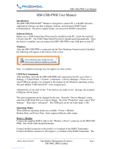
5.3 Block diagram
Pos: 14.11 /Technische Da ten / Datenblatt/ Temperatur/TTR/Techni sche Daten/Blockscha ltbild @ 15\mod_1194870 440921_3101.doc @ 139841
Sensor TTR200 Power supply
A00202
3,5 kV DC
( 2,5 kV AC 60s)~
A
1
2
3
4
-
67
8
D
DA
12 ... 30 (Ex) 42 V DC
min. 12 V DC
5
+
A
9
-
+
Fig. 4
1 24-bit A/D converter
2 Microcontroller
3 16-bit D/A converter
4 HART signal
5 Load (observe voltage drop, refer to the section "Terminal
connection diagrams")
6 Digital measuring accuracy
7 D/A measuring accuracy
8 Overall measuring accuracy
9 Terminal 11, measurement of 4 … 20 mA output current without
opening / interrupting the current loop (internal resistance
ammeter < 15 )
Pos: 14.12 /==== === Seitenumbruch ======= = @ 0\mod_1126532365768_3101.d oc @ 3830

Electrical connection
16 TTR200 OI/TTR200-EN
Pos: 14.13 /Überschri ften/1.1/1-spa ltig/S - U/Standardan wendung @ 16\mod_11980739125 00_3101.doc @ 146614
5.4 Standard application
Pos: 14.14 /Elektri scher Anschluss/Temper atur/TTR200/Signa l-/Versorgungsan schluss Teil 1 @ 16\mod_11981 68131718_3101.doc @ 146748
Field Control room
Fig. 5
A Transmitter
B Power supply / SPS input with supply
When connecting transmitters and power supplies, observe the following specification:
U
Mmin
≤ U
Smin
+ 0.02A x R
Ltg
Where
U
Mmin
: Minimum operating voltage of transmitter (refer to technical data for transmitter)
U
Smin
: Minimum supply voltage of repeater power supply / SPS input
R
Ltg
: Line resistance between transmitter and power supply
For HART functionality, use power supplies or SPS input cards with HART mark. If this is not
possible, the interconnection must have a resistance ≥ 250 (< 1100 ).
The signal line can be connected with or without ground. When connecting the ground (minus
side), make sure that only one side of the contact is connected to the equipotential bonding
system.

Electrical connection
OI/TTR200-EN TTR200 17
Standard application with HART functionality
Field Control room
Fig. 6
A Transmitter
B Power supply / SPS input with supply
Adding resistance R
250
increases the minimum supply voltage:
U
Mmin
≤ U
Smin
+ 0.02A x (R
Ltg
+ R
250
)
Where
U
Mmin
: Minimum operating voltage of transmitter (refer to technical data for transmitter)
U
Smin
: Minimum supply voltage of repeater power supply / SPS input
R
Ltg
: Line resistance between transmitter and power supply
R
250
: Resistance for HART functionality
Pos: 14.15 /==== === Seitenumbruch ======= = @ 0\mod_1126532365768_3101.d oc @ 3830

Electrical connection
18 TTR200 OI/TTR200-EN
Pos: 14.16 /Überschri ften/1.1/1-spa ltig/D - F/Elektrisc he Zusammenschaltung i m explosionsgefährdet en Bereich @ 16\mod_119815433 9484_3101.doc @ 146654
5.5 Electrical interconnection in explosion risk area
Pos: 14.17 /Elektri scher Anschluss/Temper atur/TTR200/Elek trische Zusammenscha ltung im explosionsgesc hützten Bereich @ 16\mod_1198162640515_310 1.doc @ 146700
Special interconnections are required for use in hazardous areas depending on the safety
requirements.
Intrinsic safety
The Power supply SPS inputs must have corresponding input protection circuits available in
order to eliminate a hazard (spark formation). An interconnection inspection must be performed.
For proof of the intrinsic safety, the electrical limit values are to be used as the basis for the
prototype test certificates of the apparatuses (devices), including capacitance and inductivity
values of the wires. The proof of the intrinsic safety is given if the following conditions are
fulfilled with comparison of the limit values of the apparatus.
Transmitter
(intrinsically safe apparatus)
Power supply / SPS input
(related apparatus)
U
i
U
o
I
i
I
o
P
i
P
o
L
i
+ L
c
(cable)
L
o
C
i
+ C
c
(cable)
C
o
Field (Ex area) Control room (secure area)
Fig. 7
A Transmitter
B Power supply SPS input
Important
Observe the “Technical specifications” and “Explosion-protection technical data” chapters (see
data sheet and/or operating instructions).
Pos: 14.18 /==== === Seitenumbruch ======= = @ 0\mod_1126532365768_3101.d oc @ 3830

Electrical connection
OI/TTR200-EN TTR200 19
Pos: 14.19 /Elektri scher Anschluss/Temper atur/TTR200/Ins tallation im explosio nsgefährdetem Bereic h @ 15\mod_1195572347828_ 3101.doc @ 141910
5.5.1 Installation in ignition protection areas
Transmitters can be installed in a wide variety of industrial sectors. Systems that requires
ignition protection are divided into zones. As a result, different instruments are also required.
For additional information, refer to the section “Explosion-protection relevant information” or the
data sheet.
5.5.2 Zone 0
Transmitter design: II 1G EEx ia IIC T6
Zone 0 Explosion-protection zone 0 Safety area
Fig. 8
A Sensor
B Transmitter in housing with IP 20 level of
protection
C Power supply [EEx ia]
For instruments in zone 0, the input for the repeater must be in [EEx ia] design.
When using the transmitter in zone 0, make sure you prevent electrostatic charging of the
temperature transmitter (observe warnings on equipment).
The sensor must be used by the user in accordance with applicable ignition-protection
standards.

Electrical connection
20 TTR200 OI/TTR200-EN
5.5.3 Zone 1 (0)
Transmitter design: II 2 (1) G EEx [ia] ib IIC T6
Zone 0 or Zone 1 Explosion-protection zone 1 Safety area
BC
ib
A00209
ia
J
A
Fig. 9
A Sensor
B Transmitter in housing with IP 20 level of
protection
C Power supply [EEx ib]
For instruments in zone 1, the input for the repeater must be at minimum in [EEx ib] design.
The sensor must be used by the user in accordance with applicable ignition-protection
standards. It can be installed in zone 1 or zone 0.
/