ABB Endura ACA592 Operating Instructions Manual
- Type
- Operating Instructions Manual

—
ABB MEASUREMENT & ANALYTICS | OPERATING INSTRUCTION | OI/ACA592/EC-EN REV. B
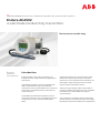
Endura ACA592
4-electrode conductivity transmitter
Measurement made easy
Introduction
Endura ACA592 4-electrode transmitters are
suitable for wide-range conductivity applications
and slurries.
The ACA592 transmitter is fully compatible with
ABB’s comprehensive range of 4-electrode
conductivity sensors and enables users to measure
conductivity in applications from clean water to
harsh chemicals.
The ACA592 has automatic temperature sensor
recognition for both 2- and 3-wire RTD inputs from
common inputs such as Pt100, Pt1000 and 3k
Balco.
ACA592 transmitters are communication-ready
field devices with microprocessor-controlled
electronics. For bi-directional communication, an
FSK signal is superimposed on the 4 to 20 mA
output signal via the HART protocol.
The device type manager (DTM) can be used to
configure, poll and test devices on a PC. Handheld
terminals such as the DHH801 also support
communication.
The transmitter is equipped with an LCD display
used to show the current process data. The 4 keys
beneath the transmitter enable local configuration.
—
Rugged design
transmitter for
industrial applications

For more information
Further publications for the Endura ACA592 4-electrode
transmitter are available for free download from:
www.abb.com/analytical
See links and reference numbers below or scan this code:
Description Search for or click on
Data Sheet
Endura ACA592
Conductivity transmitter
DS/ACA592-EN
Addendum
RoHS Directive
2011/65/EU (RoHS II)
ADD/MEASUREMENT/001-EN

Endura ACA592
4-electrode conductivity transmitter Contents
OI/ACA592/EC–EN Rev. B 1
Contents
1 Safety ............................................................................................................................................... 4
1.1 Technical Limits ....................................................................................................................... 4
1.2 Operator Liability ...................................................................................................................... 4
1.2.1 Operating Safety Information ......................................................................................... 4
1.2.2 Special Conditions of Use (FM Approval) ....................................................................... 4
1.3 Health & Safety ........................................................................................................................ 5
1.4 Electrical Safety – IEC / EN 61010-1 ........................................................................................5
1.4.1 Electrical Installation Safety Information ......................................................................... 5
1.5 Symbols – EN / IEC 61010-1 ................................................................................................... 6
1.6 Product Recycling Information ................................................................................................. 7
1.7 Product Disposal ..................................................................................................................... 8
1.7.1 Information on WEEE Directive 2002/96/EC
(Waste Electrical and Electronic Equipment) .................................................................. 8
1.8 Returning Transmitters ............................................................................................................. 9
1.8.1 Transport Safety Information .......................................................................................... 9
1.9 Restriction of Hazardous Substances (RoHS) .......................................................................... 9
1.10 Safety Precautions ................................................................................................................... 9
1.11 Safety Conventions ................................................................................................................ 10
1.12 Safety Recommendations ...................................................................................................... 10
1.13 Service and Repairs ............................................................................................................... 10
1.14 Potential Safety Hazards ........................................................................................................ 10
2 Use in Areas Requiring Ignition Protection .................................................................................. 11
2.1 Approvals .............................................................................................................................. 11
2.1.1 CE Mark ...................................................................................................................... 11
2.1.2 Ignition Protection .......................................................................................................11
2.2 Ground .................................................................................................................................. 11
2.3 Interconnection ...................................................................................................................... 11
2.4 Configuration ......................................................................................................................... 11
2.5 Hazardous Area Relevant Information .................................................................................... 12
2.5.1 ACA592-XX.A1… (Intrinsic Safety) ............................................................................... 12
2.5.2 ACA592-XX.A2… (Flameproof Protection) ................................................................... 13
2.5.3 ACA592-XX.A3… (Type n Non-sparking) ..................................................................... 13
2.5.4 ACA592-XX.F1 or .C1 (Intrinsic Safety) ........................................................................ 14
2.5.5 ACA592-XX.F2 or .C2 (Explosion-proof) ...................................................................... 15
2.5.6 ACA592-XX.F3 or .C3 (Non-incendive) ........................................................................ 15
3 Mechanical Installation .................................................................................................................. 17
3.1 Hazardous Area Installation ................................................................................................... 17
3.2 Non-hazardous area installation .............................................................................................17
3.3 Installation Conditions ............................................................................................................ 18
3.4 Dimensions ............................................................................................................................ 19
3.4.1 Transmitter-only Dimensions (Excluding Mounting Bracket) ......................................... 19
3.4.2 Wall-mount Transmitter Dimensions ............................................................................ 20
3.4.3 Pipe-mount Transmitter Dimensions ............................................................................ 21
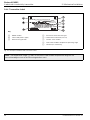
3.4.4 Transmitter Label .........................................................................................................22
3.4.5 'HazLoc' Labels .......................................................................................................... 23
3.4.6 Aligning the Cartridge LCD Display .............................................................................. 25

Endura ACA592
4-electrode conductivity transmitter Contents
2 OI/ACA592/EC–EN Rev. B
4 Electrical Installation ...................................................................................................................... 26
4.1 Cable Glands and Plugs ......................................................................................................... 26
4.1.1 ACA592–XX for Intrinsically Safe, Type n and Non-incendive Installations .................... 26
4.1.2 ACA592–XX Ex d Models without Cable Gland ............................................................ 26
4.2 DC Power Supply Connections .............................................................................................. 28
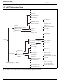
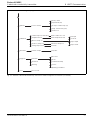
4.3 Sensor Connections ............................................................................................................... 29
4.3.1 ACA592 4-Electrode Conductivity Transmitter – Sensor Connections .......................... 30
4.4 Integral Sensor Cable Connection .......................................................................................... 31
4.5 Junction Box and Extension Cable Connection ......................................................................31
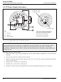
4.6 Power Supply Requirements .................................................................................................. 32
4.6.1 Standard Application ................................................................................................... 32
4.6.2 Standard Application with HART Functionality .............................................................. 33
4.6.3 Electrical Connection in Hazardous Area ...................................................................... 34
4.6.4 Installation in Hazardous Areas .................................................................................... 35
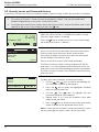
5 Start-up and Operation .................................................................................................................. 39
5.1 Navigating Menus and Parameters ......................................................................................... 39
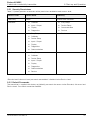
5.2 Security Levels and Password Access ................................................................................... 40
5.2.1 Security Permissions ....................................................................................................41
5.2.2 Default Passwords ....................................................................................................... 41
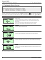
5.3 Configuration Menus Overview ............................................................................................... 42
6 Configuration .................................................................................................................................. 44
6.1 Configuration Options ............................................................................................................ 44
6.2 Configuration DIP Switch .......................................................................................................45
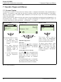
7 Operator Pages and Menus ...........................................................................................................46
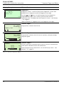
7.1 Process Display ..................................................................................................................... 46
7.1.1 Operator Pages ........................................................................................................... 47
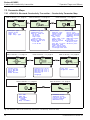
7.2 Parameter Maps .................................................................................................................... 50
7.2.1 ACA592 4-Electrode Conductivity Transmitter – Conductivity Parameter Map .............50
7.2.2 ACA592 4-Electrode Conductivity Transmitter – Concentration Parameter Map ........... 51
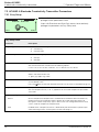
7.3 ACA592 4-Electrode Conductivity Transmitter Parameters ..................................................... 52
7.3.1 Easy Setup .................................................................................................................. 52
7.3.2 Calibrate ...................................................................................................................... 53
7.3.3 Device Setup ............................................................................................................... 55
7.3.4 Input/Output ................................................................................................................58
7.3.5 Display ......................................................................................................................... 59
7.3.6 Diagnostics .................................................................................................................. 60
7.3.7 Communication ........................................................................................................... 61
7.3.8 Service ........................................................................................................................ 62
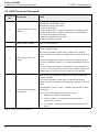
8 Troubleshooting and Diagnostics ................................................................................................. 63
8.1 Diagnostic Messages ............................................................................................................. 64
8.2 Diagnosis Screens ................................................................................................................. 69
8.2.1 ACA592 4-Electrode Conductivity Transmitter – Diagnosis Overview Screen ............... 69
8.2.2 ACA592 4-Electrode Conductivity Transmitter – Diagnosis Masking ............................ 70
8.2.3 ACA592 4-Electrode Conductivity Transmitter – Diagnosis Simulation ......................... 71

Endura ACA592
4-electrode conductivity transmitter Contents
OI/ACA592/EC–EN Rev. B 3
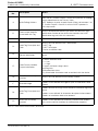
9 HART Communication ................................................................................................................... 73
9.1 HART Device Type Codes ..................................................................................................... 73
9.2 HART Configuration Map ....................................................................................................... 74
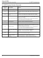
9.3 HART Universal Commands .................................................................................................. 76
9.4 HART Common Practice Commands .................................................................................... 78
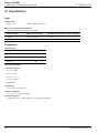
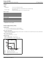
10 Specification .................................................................................................................................. 80
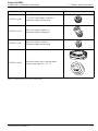
11 Spares and Accessories ................................................................................................................ 84
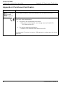
Appendix A Permits and Certification ................................................................................................ 86
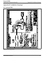
Appendix B Installation Drawings ...................................................................................................... 87
B.1 Drawing P0908 ...................................................................................................................... 87
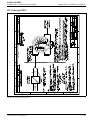
B.2 Drawing P0909 ...................................................................................................................... 88
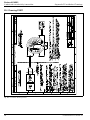
B.3 Drawing P0910 ...................................................................................................................... 89
B.4 Drawing P0911 ...................................................................................................................... 90

Endura ACA592
4-electrode conductivity transmitter 1 Safety
4 OI/ACA592/EC–EN Rev. B
1 Safety
Information in this manual is intended only to assist our customers in the efficient operation of our
equipment. Use of this manual for any other purpose is specifically prohibited and its contents are not to be
reproduced in full or part without prior approval of the Technical Publications Department.
1.1 Technical Limits
The transmitter is designed for use exclusively within the stated values on the name plate and in the
technical specifications (see Specifications, page 80). These must be complied with accordingly:
Do not exceed the maximum / permitted operating temperature.
Observe the housing protection system.
1.2 Operator Liability
When measuring corrosive and abrasive materials, the operator must examine the resistance of all parts
that come into contact with the process being measured. ABB will assist with the selection but cannot,
however, accept any liability.
Operators must strictly observe the national regulations applicable in their countries with regards to
installation, functional tests, repairs and maintenance of electrical devices.
1.2.1 Operating Safety Information
Before switching on, ensure that the specified environmental conditions in the Specifications section
(page 80) are complied with and that the power supply voltage corresponds with the voltage of the
transmitter.
When there is a chance that safe operation is no longer possible, put the transmitter out of operation and
secure against unintended operation.
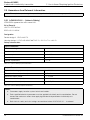
1.2.2 Special Conditions of Use (FM Approval)
ACA592–XX transmitters are approved for connection to ABB conductivity sensor types:
Warning.
System configuration must be carried out only by users or personnel with approved access rights
(user privileges).
Read all relevant sections of this guide before configuring the system or modifying system
parameters.
Install and use this equipment as detailed in this guide. Install and use associated equipment in
accordance with the relevant national and local standards. Installation and repair must only be
carried out by the manufacturer, authorized agents or persons conversant with the construction
standards for hazardous area certified equipment.
2025 2278 TB26 TB452 TB464
2045 AC2 TB264 TB456 TB465
2077 TB25 TB27 TB457 TB468
2078 TB254 TB404 TB458 TB471
2085 TB256 TB451 TB461 TB475

Endura ACA592
4-electrode conductivity transmitter 1 Safety
OI/ACA592/EC–EN Rev. B 5
1.3 Health & Safety
1.4 Electrical Safety – IEC / EN 61010-1
This equipment complies with the requirements of IEC / EN 61010-1 'Safety Requirements for Electrical
Equipment for Measurement, Control and Laboratory Use' and complies with applicable electrical codes
NEC and CEC.
If the equipment is used in a manner NOT specified by the Company, the protection provided by the
equipment may be impaired.
1.4.1 Electrical Installation Safety Information
Electrical connection may be performed only by authorized personnel according to the electrical codes of
the country of destination.
Observe the electrical connection information in this publication. Failure to do so may affect the electrical
protection of the transmitter.
The secure isolation of contact-dangerous electrical circuits is guaranteed only when the connected
devices fulfil the requirements of the applicable electrical codes, or DIN VDE 0106 T.101 (basic
requirements for secure isolation ['VDE' may not be applicable for NAM]).
For secure isolation, route the process supply lines separately from electrical circuits or additionally isolate
them.
Health and Safety
To ensure that our products are safe and without risk to health, the following points must be noted:
The relevant sections of these instructions must be read carefully before proceeding.
Warning labels on containers and packages must be observed.
Installation, operation, maintenance and servicing must only be carried out by suitably trained
personnel and in accordance with the information given.
Normal safety precautions must be taken to avoid the possibility of an accident occurring when
operating in conditions of high pressure and / or temperature.
Safety advice concerning the use of the equipment described in this manual or any relevant Material
Safety Data Sheets (where applicable) may be obtained from the Company address on the back cover,
together with servicing and spares information.

Endura ACA592
4-electrode conductivity transmitter 1 Safety
6 OI/ACA592/EC–EN Rev. B
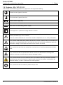
1.5 Symbols – EN / IEC 61010-1
One or more of the following symbols may appear on the equipment labelling:
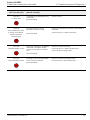
Protective earth (ground) terminal.
Functional earth (ground) terminal.
Direct current supply only.
Alternating current supply only.
Both direct and alternating current supply.
The equipment is protected through double insulation.
This symbol, when noted on a product, indicates a potential hazard which could cause
serious personal injury and / or death.
The user should reference this instruction manual for operation and / or safety information.
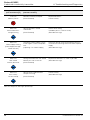
This symbol, when noted on a product enclosure or barrier, indicates that a risk of electrical
shock and / or electrocution exists and indicates that only individuals qualified to work with
hazardous voltages should open the enclosure or remove the barrier.
This symbol indicates that the marked item can be hot and should not be touched without
care.
This symbol indicates the presence of devices sensitive to electrostatic discharge and
indicates that care must be taken to prevent damage to them.
This symbol identifies a risk of chemical harm and indicates that only individuals qualified
and trained to work with chemicals should handle chemicals or perform maintenance on
chemical delivery systems associated with the equipment.
This symbol indicates the need for protective eye wear.

Endura ACA592
4-electrode conductivity transmitter 1 Safety
OI/ACA592/EC–EN Rev. B 7
1.6 Product Recycling Information
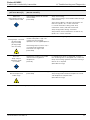
This symbol indicates the need for protective hand wear.
Electrical equipment marked with this symbol may not be disposed of in European public
disposal systems. In conformity with European local and national regulations, European
electrical equipment users must now return old or end-of-life equipment to the manufacturer
for disposal at no charge to the user.
Products marked with this symbol indicates that the product contains toxic or hazardous
substances or elements. The number inside the symbol indicates the environmental
protection use period in years.
Electrical equipment marked with this symbol may not be disposed of in European public
disposal systems after 12 August 2005. In conformity with European local and national
regulations (EU Directive 2002 / 96 / EC), European electrical equipment users must now
return old or end-of-life equipment to the manufacturer for disposal at no charge to the user.
Note. For return for recycling, please contact the equipment manufacturer or supplier for instructions
on how to return end-of-life equipment for proper disposal.

Endura ACA592
4-electrode conductivity transmitter 1 Safety
8 OI/ACA592/EC–EN Rev. B
1.7 Product Disposal
ABB, Inc. actively promotes environmental consciousness and has an operational management system in
accordance with DIN EN ISO 9001, EN ISO 14001 and OHSAS 18001. Our products and solutions should
have minimum impact on the environment and persons during manufacture, storage, transport, use and
disposal. This includes the environmentally friendly use of natural resources. Through its publications ABB
conducts an open dialog with the public.
The ACA592-XX transmitter is manufactured from materials that can be reused by specialized recycling
companies.
1.7.1 Information on WEEE Directive 2002/96/EC
(Waste Electrical and Electronic Equipment)
This product is not subject to the WEEE directive 2002/96/EC and relevant national laws (for example,
ElektroG in Germany).
Dispose of the ACA592-XX transmitter directly in a specialized recycling facility. Do not use municipal
garbage. Only privately used products may be disposed of in municipal garbage according to the WEEE
directive 2002/96/EC. Proper disposal prevents negative effects on people and the environment, and
supports the reuse of valuable raw materials.
If it is not possible to dispose of old equipment correctly, ABB Service will accept and dispose of returns for
a fee.
Note. The following applies only to European customers.
ABB is committed to ensuring that the risk of any environmental damage or pollution caused
by any of its products is minimized as far as possible. The European Waste Electrical and
Electronic Equipment (WEEE) Directive (2002 / 96 / EC) that came into force on August 13
2005 aims to reduce the waste arising from electrical and electronic equipment; and
improve the environmental performance of all those involved in the life cycle of electrical and
electronic equipment.
In conformity with European local and national regulations (EU Directive 2002 / 96 / EC
stated above), electrical equipment marked with the above symbol may not be disposed of
in European public disposal systems after 12 August 2005.

Endura ACA592
4-electrode conductivity transmitter 1 Safety
OI/ACA592/EC–EN Rev. B 9
1.8 Returning Transmitters
Use the original packaging or suitably secure packaging for returning the transmitter for repair or
recalibration. Contact the local ABB office or sales representative for return authorization number and
address.
All transmitters returned for service or repair to ABB must be free from any hazardous materials (acids,
alkali, solvents, etc.).
1.8.1 Transport Safety Information
Observe the following information:
Do not expose the transmitter to moisture during transport. Pack the transmitter accordingly.
Pack the transmitter so that it is protected from vibration during transport, e.g. through air-cushioned
packaging.
Check the transmitter for possible damage that may have occurred from improper transport. Damages in
transit must be recorded on the transport documents. All claims for damages must be claimed against the
shipper and before the installation.
1.9 Restriction of Hazardous Substances (RoHS)
1.10 Safety Precautions
Please read the entire manual before unpacking, setting up, or operating this instrument.
Pay particular attention to all warning and caution statements. Failure to do so could result in serious injury
to the operator or damage to the equipment.
To ensure the protection provided by this equipment is not impaired, do not use or install this equipment in
any manner other than that which is specified in this manual.
The European Union RoHS Directive and subsequent regulations introduced in member
states and other countries limits the use of six hazardous substances used in the
manufacturing of electrical and electronic equipment. Currently, monitoring and control
instruments do not fall within the scope of the RoHS Directive, however ABB has taken
the decision to adopt the recommendations in the Directive as the target for all future
product design and component purchasing.
RoHS

Endura ACA592
4-electrode conductivity transmitter 1 Safety
10 OI/ACA592/EC–EN Rev. B
1.11 Safety Conventions
1.12 Safety Recommendations
For safe operation, it is imperative that these service instructions be read before use and that the safety
recommendations mentioned herein be scrupulously respected. If danger warnings are not heeded to,
serious material or bodily injury could occur.
1.13 Service and Repairs
Other than the serviceable items listed in Section 11, page 84, none of the transmitter's components can
be serviced by the user. Only personnel from ABB or its approved representative(s) is (are) authorized to
attempt repairs to the system and only components formally approved by the manufacturer should be
used. Any attempt at repairing the instrument in contravention of these principles could cause damage to
the instrument and corporal injury to the person carrying out the repair. It renders the warranty null and void
and could compromise the correct working of the instrument and the electrical integrity or the CE
compliance of the instrument.
If you have any problems with installation, starting, or using the instrument please contact the company that
sold it to you. If this is not possible, or if the results of this approach are not satisfactory, please contact the
manufacturer's Customer Service.
1.14 Potential Safety Hazards
The following potential safety hazards are associated with operating the system:
Electrical (line voltage)
Use in hazardous areas
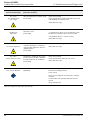
Warning. Indicates a condition which, if not met, could cause serious personal injury and / or death.
Do not move beyond a warning until all conditions have been met.
If a warning sign appears on the instrument itself, refer to Precautionary Labels – product certification
and Electrical Safety – EN / IEC 61010-1 for an explanation.
Caution. Indicates a condition which, if not met, could cause minor or moderate personal injury and /
or damage to the equipment. Do not move beyond a caution until all conditions have been met.
Note. Indicates important information or instructions that should be considered before operating the
equipment.
Note. The transmitter uses a capacitive touch display. Ensure the glass cover is kept in a clean
condition to avoid contact problems caused by a dirty screen.

Endura ACA592
4-electrode conductivity transmitter 2 Use in Areas Requiring Ignition Protection
OI/ACA592/EC–EN Rev. B 11
2 Use in Areas Requiring Ignition Protection
Special regulations must be observed in explosion-protection zones for the auxiliary power connection,
signal inputs/outputs and ground connection.
2.1 Approvals
2.1.1 CE Mark
The ACA592–EC including type B LCD display / configuration software meets all requirements for the CE
mark in accordance with applicable EC Directives 2004/108/EC (EMC), 2006/95/EC (LVD) and 94/9/EC
(ATEX).
2.1.2 Ignition Protection
This transmitter is FM, CSA and ATEX/IEC approved – see Section 2.5, page 12 for hazardous area
relevant information.
2.2 Ground
If for functional reasons, the intrinsically safe circuit must be grounded by connecting it to an equipotential
bonding system, it must be grounded at a single location only.
2.3 Interconnection
If ACA592 transmitters are operated in an intrinsically safe circuit, proof of interconnection may be required
during the installation. In general, intrinsically safe circuits require proof of interconnection.
2.4 Configuration
ACA592 transmitters can be installed in hazardous areas in compliance with proof-of-interconnection and
directly in a hazardous area using approved handheld HART terminals (proof of interconnection may be
required during the installation) as well as by coupling an ignition-proof modem to the circuit outside the
explosion-protection area.
Caution.
All parts must be installed in accordance with manufacturer information and relevant standards
and regulations.
Startup and operation must be performed in accordance with ATEX User Directive 99/92/EC or
BetrSichV (EN60079-14).

Endura ACA592
4-electrode conductivity transmitter 2 Use in Areas Requiring Ignition Protection
12 OI/ACA592/EC–EN Rev. B
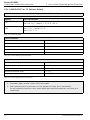
2.5 Hazardous Area Relevant Information
2.5.1 ACA592-XX.A1… (Intrinsic Safety)
ATEX/IECEx approved for use in zone 0/20.
Ex ia (Zone 0):
LCIE 11 ATEX 3058 X
IECEx LCI 11.0050X
Designation
Device design: II 1 G Ex ia IIC T4
Housing design: II 1 D Ex iaD A20 IP66 T135 ºC, –20 ºC T
amb 60 ºC
Safety-relevant data
Note. The explosion-proof or ignition-proof designation is displayed on the agency certification label.
Input Parameters
Maximum voltage U
i = 30 V
Maximum input current Ii = 160 mA
Maximum power P
i = 0,8 W
Internal inductance L
i = 0,5 mH
Internal capacitance C
i = 5 nF
Table 2.1 Intrinsic Safety Input Parameters
Output Parameters
Open-circuit voltage (maximum) U
o = 11.8 V
Short-circuit current (maximum) I
o = 5 mA
Maximum output power P
o = 15 mW
Allowed inductance (total) L
a = 1 H
Allowed capacitance (total) C
a = 1.45 µF
Table 2.2 Intrinsic Safety Output Parameters
Notes.
Parameters apply to entire system inclusive of cables.
Each specified electrical parameter must be applied individually and in combination. Do not
exceed the maximum values when applying the electrical parameters individually or in
combination.
Both Intrinsic safety and dust ratings are combined when ACA592-XX.A1… is ordered.

Endura ACA592
4-electrode conductivity transmitter 2 Use in Areas Requiring Ignition Protection
OI/ACA592/EC–EN Rev. B 13
2.5.2 ACA592-XX.A2… (Flameproof Protection)
ATEX approved for use in Zone 1/21.
Ex d (Zone 1):
LCIE 11 ATEX 3057 X
IECEx LCI 11.0049X
Designation
Device design: II 2 G Ex d IIC T4
Housing design: II 2 D Ex tD A21 IP66 T135 ºC, – 20 ºC T
amb 60 ºC
2.5.3 ACA592-XX.A3… (Type n Non-sparking)
ATEX/IECEx approved for use in zone 2/22.
Ex nA (Zone 2):
LCIE 11 ATEX 1005 X
IECEx LCI 11.0048X
Designation
Device design: II 3 G Ex nA IIC T4
Housing design: II 3 D Ex tD A22 IP66 T135 ºC, –20 ºC T
amb 60ºC
ABB statement of conformity in accordance with ATEX directive.
Note. Both flameproof and dust ratings are combined when ACA592-XX.A2… is ordered.
Note. Both type n and dust ratings are combined when ACA592-XX.A3… is ordered.

Endura ACA592
4-electrode conductivity transmitter 2 Use in Areas Requiring Ignition Protection
14 OI/ACA592/EC–EN Rev. B
2.5.4 ACA592-XX.F1 or .C1 (Intrinsic Safety)
Note. See installation drawings P0908 – FM (page 87), or P0910 – CSA (page 89) for allowable sensors.
Agency Area Classification
FM
Class I, Div. 1, Groups A, B, C, D
Class II/III, Div. 1, Group E, F, G; T4 Ta = 60 ºC
CSA
Class I, Div. 1, Groups A, B, C, D
Class II, Div. 1, Groups E, F, G
Class III; Div. 1: T4
Table 2.3 Intrinsically Safe
Input Parameters
Maximum voltage U
i = 30 V
Maximum input current Ii = 160 mA
Maximum power P
i = 0,8 W
Internal inductance L
i = 0,5 mH
Internal capacitance C
i = 5 nF
Table 2.4 Intrinsic Safety Input Parameters
Output Parameters
Open-circuit voltage (maximum) U
o = 11.8 V
Short-circuit current (maximum) I
o = 5 mA
Maximum output power P
o = 15 mW
Allowed inductance (total) L
a = 1 H
Allowed capacitance (total) C
a = 1.45 µF
Table 2.5 Intrinsic Safety Output Parameters
Notes.
Parameters apply to entire system inclusive of cables.
Each specified electrical parameter must be applied individually and in combination.
Do not exceed the maximum values when applying the electrical parameters individually or in
combination.

Endura ACA592
4-electrode conductivity transmitter 2 Use in Areas Requiring Ignition Protection
OI/ACA592/EC–EN Rev. B 15
2.5.5 ACA592-XX.F2 or .C2 (Explosion-proof)
2.5.6 ACA592-XX.F3 or .C3 (Non-incendive)
Agency Area Classification
FM
XP, Class I, Div. 1, Groups A, B, C, D
Class II/III, Div. 1, Group F, G; T4 Ta = 60 ºC
CSA
Class I, Div. 1, Groups A, B, C, D
Class II, Div. 1; Groups E, F, G
Class III; Div. 1; T4
Table 2.6 Explosion-proof
Note. See installation drawings P0909 – FM (page 88), or P0911 – CSA (page 90) for allowable sensors.
Agency Approvals
FM
Class I, Div. 2, Groups A, B, C, D
Class II/III, Div. 2, Group F, G; T4 Ta = 60 ºC
CSA
Class I, Div. 2, Groups A, B, C, D
Class II, Div. 2, Groups F, G
Class III; Div 2; T4
Table 2.7 Non-incendive
Input Parameters
Maximum voltage U
i = 30 V
Maximum input current current controlled by transmitter
Internal inductance L
i = 0,5 mH
Internal capacitance C
i = 5 nF
Table 2.8 Non-incendive Field Wiring – FM and CSA: Input Parameters
Note. For installation not using Associated Equipment, maximum voltage is 42 V DC and input wiring
must be installed per Div. 2 wiring methods in accordance with the applicable Electrical Code of the
country in use.

Endura ACA592
4-electrode conductivity transmitter 2 Use in Areas Requiring Ignition Protection
16 OI/ACA592/EC–EN Rev. B
Output Parameters
Open-circuit voltage (maximum) U
o = 11.8 V
Short-circuit current (maximum) I
o = 5 mA
Maximum output power P
o = 15 mW
Allowed inductance (total) L
a = 1 H
Allowed capacitance (total) C
a = 1.45 µF
Table 2.9 Non-incendive Field Wiring – FM and CSA: Output Parameters
Notes.
Parameters apply to entire system inclusive of cables.
Each specified electrical parameter must be applied individually and in combination. Do not
exceed the maximum values when applying the electrical parameters individually or in
combination.

Endura ACA592
4-electrode conductivity transmitter 3 Mechanical Installation
OI/ACA592/EC–EN Rev. B 17
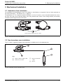
3 Mechanical Installation
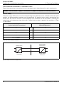
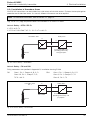
3.1 Hazardous Area Installation
For hazardous area designation, the Ex installation is described on a separate 'HazLoc' label mounted on
the transmitter body – see Section 3.4.5, page 23.
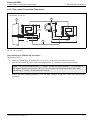
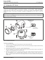
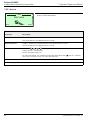
For protection in Ex d / explosion-proof installations, turn the 2 security screws (located beneath the covers
on front and rear of the housing body) until they prevent both covers from being rotated (unscrewed)
therefore preventing removal of the covers.
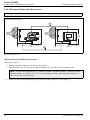
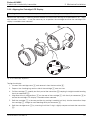
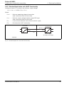
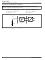
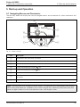
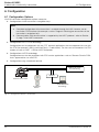
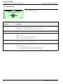
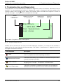
3.2 Non-hazardous area installation
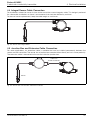
Fig. 3.2 shows a general purpose non-hazardous installation and is for reference only.
Fig. 3.1 Transmitter Cover Security Screws
Fig. 3.2 Installation in Non-Hazardous Area
Front and rear cover security screws
Key:
A Signal / power supply cable
B ACA592 transmitter
C Sensor connection
cable
D Sensor

Endura ACA592
4-electrode conductivity transmitter 3 Mechanical Installation
18 OI/ACA592/EC–EN Rev. B
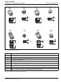
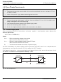
3.3 Installation Conditions
Ensure the following installation conditions are met:
1. Install the transmitter with consideration to ambient conditions.
2. Locate the transmitter in a position where the temperature and humidity specifications are not
exceeded and ensure the transmitter is protected from direct sunlight, rain, snow and hail.
3. Ensure the transmitter operating temperature is within the range –20 to 60 °C (–4 to 140 °F).
4. Select a location away from strong electrical and magnetic fields.
Page is loading ...
Page is loading ...
Page is loading ...
Page is loading ...
Page is loading ...
Page is loading ...
Page is loading ...
Page is loading ...
Page is loading ...
Page is loading ...
Page is loading ...
Page is loading ...
Page is loading ...
Page is loading ...
Page is loading ...
Page is loading ...
Page is loading ...
Page is loading ...
Page is loading ...
Page is loading ...
Page is loading ...
Page is loading ...
Page is loading ...
Page is loading ...
Page is loading ...
Page is loading ...
Page is loading ...
Page is loading ...
Page is loading ...
Page is loading ...
Page is loading ...
Page is loading ...
Page is loading ...
Page is loading ...
Page is loading ...
Page is loading ...
Page is loading ...
Page is loading ...
Page is loading ...
Page is loading ...
Page is loading ...
Page is loading ...
Page is loading ...
Page is loading ...
Page is loading ...
Page is loading ...
Page is loading ...
Page is loading ...
Page is loading ...
Page is loading ...
Page is loading ...
Page is loading ...
Page is loading ...
Page is loading ...
Page is loading ...
Page is loading ...
Page is loading ...
Page is loading ...
Page is loading ...
Page is loading ...
Page is loading ...
Page is loading ...
Page is loading ...
Page is loading ...
Page is loading ...
Page is loading ...
Page is loading ...
Page is loading ...
Page is loading ...
Page is loading ...
Page is loading ...
Page is loading ...
Page is loading ...
Page is loading ...
-
 1
1
-
 2
2
-
 3
3
-
 4
4
-
 5
5
-
 6
6
-
 7
7
-
 8
8
-
 9
9
-
 10
10
-
 11
11
-
 12
12
-
 13
13
-
 14
14
-
 15
15
-
 16
16
-
 17
17
-
 18
18
-
 19
19
-
 20
20
-
 21
21
-
 22
22
-
 23
23
-
 24
24
-
 25
25
-
 26
26
-
 27
27
-
 28
28
-
 29
29
-
 30
30
-
 31
31
-
 32
32
-
 33
33
-
 34
34
-
 35
35
-
 36
36
-
 37
37
-
 38
38
-
 39
39
-
 40
40
-
 41
41
-
 42
42
-
 43
43
-
 44
44
-
 45
45
-
 46
46
-
 47
47
-
 48
48
-
 49
49
-
 50
50
-
 51
51
-
 52
52
-
 53
53
-
 54
54
-
 55
55
-
 56
56
-
 57
57
-
 58
58
-
 59
59
-
 60
60
-
 61
61
-
 62
62
-
 63
63
-
 64
64
-
 65
65
-
 66
66
-
 67
67
-
 68
68
-
 69
69
-
 70
70
-
 71
71
-
 72
72
-
 73
73
-
 74
74
-
 75
75
-
 76
76
-
 77
77
-
 78
78
-
 79
79
-
 80
80
-
 81
81
-
 82
82
-
 83
83
-
 84
84
-
 85
85
-
 86
86
-
 87
87
-
 88
88
-
 89
89
-
 90
90
-
 91
91
-
 92
92
-
 93
93
-
 94
94


ABB Endura ACA592 Operating Instructions Manual
- Type
- Operating Instructions Manual
Ask a question and I''ll find the answer in the document
Finding information in a document is now easier with AI
Related papers
-
ABB Endura APA592 Operating
-
-
-
ABB 261GC Operating
-
-
-
-
-
-
Other documents
-
Murphy Mark IV Digital Fault Annunciator Tattletale Installation Diagram
-
-
Rosemount Solu Comp Xmt-P-FF/FI Owner's manual
-
-
-
Emerson 5081-T User manual
-
Omega SBG144600 Owner's manual
-
-
-