ABB PGS100 Operating
- Category
- Measuring, testing & control
- Type
- Operating
This manual is also suitable for

—
ABB MEASUREMENT & ANALYTICS | OPERATING INSTRUCTION
PGS100 and PAS100
Gauge and absolute pressure transmitters
Engineered solutions for all
applications
Measurement made easy
Introduction
The present manual provides information on
installing, operating, troubleshooting the PGS and
PAS pressure transmitter models. Every section of
the present manual is specifically dedicated to the
specific phase of the transmitter lifecycle starting
from the receipt of the transmitter and its
identification, passing to the installation, to the
electrical connections, to the configuration and to
the troubleshooting and maintenance operations,
as applicable.
The pressure transmitters model PGS and PAS are
field mounted, microprocessor based electronic
transmitters. Accurate and reliable measurement of
gauge and absolute pressure is provided, in the even
most difficult and hazardous industrial
environments. These models can be configured to
provide specific industrial output signals according
to 4 to 20mA with HART digital communication.
For more information
Further publications for PGS and PAS family of
pressure products are available for free download
from:
www.abb.com/measurement
or by scanning this code:
Download the Brochure or search for
RB/PGS/PAS100-EN on https://library.abb.com/en.
—
PGS100/PAS100 model

2 PGS100 AND PAS100 | PRESSURE TRANSMITTERS | OI/PGS/PAS100-EN REV. A
Contents
1 Safety ..................................... 4
General safety information. . . . . . . . . . . . . . . . . . . . . . . . . 4
Improper use ...................................... 4
Technical limit values .............................. 4
Warranty provision ................................ 4
Use of instruction ................................. 4
Operator liability ...................................5
Qualified personnel ................................5
Returning devices ..................................5
Disposal ...........................................5
Information on WEEE Directive 2012/19/EU
(Waste Electrical and Electronic Equipment) .........5
Transport and storage ..............................5
Safety information for electrical installation .........5
Safety information for inspection and maintenance . 6
Cyber security .................................... 6
Disclaimer....................................6
Communication protocol specific..............6
2 Transmitter overview ........................7
Transmitter components overview ..................7
Range and span consideration ......................7
3 Opening the box .............................8
Identification plates ............................... 8
Optional wired-on plate ........................... 8
Handling and storage .............................. 9
4 Mounting ...................................9
General ........................................... 9
IP protection and designation ......................10
Mounting the transmitter ..........................10
Transmitter factory configuration
consideration ...............................10
Hazardous area considerations...............10
Pressure Equipment Directive (PED)
(2014/68/EU) .....................................10
Devices with PS >200 ........................10
Devices with PS ≤ 200 ........................10
Mounting a P style pressure transmitter ............11
Sealing and screw connections .....................11
Moisture ..........................................11
Measuring pipe ...................................12
5 Transmitter wiring..........................13
Supply requirement ...............................13
Cable connection ..................................13
Wiring procedure ..................................14
Grounding ........................................14
Output (HART) transmitter wiring ..................15
Communication setup .............................15
6 Commissioning .............................16
General remarks ...................................16
Output signal .....................................16
Output current limits for analog only version ..16
Output current limits for HART and analog
version (according to NAMUR NE 43 standard). 16
Zero/Span and write protection ....................16
Local display ......................................17
Adjusting lower range value / oblique sensors ......18
Installing/Removing the LCD display ...............19
Pressure sensor ventilation (PGS100 only) ......... 20

PGS100 AND PAS100 | PRESSURE TRANSMITTERS | OI/PGS/PAS100-EN REV. A
3
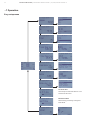
7 Operation (only HART version) ..............21
LCD display. .......................................21
Local diagnostic menu. ............................21
LCD menu structure. ..............................21
Easy setup menu ................................. 22
8 Error messages .............................23
LCD display messages ............................ 23
Error states and alarms ........................... 23
QR code Digital Advanced Diagnostic (DAD) ....... 26
QR code Channel Partner Support ................. 26
9 Maintenance / Repair .......................27
Returns and removal ...............................27
10 Hazardous Area considerations............. 28
Special condition for safe use (X) .................. 28
Explosion protection ............................. 28
Type-examination certificate/Declaration of
conformity ....................................... 28
Type of protection “intrinsic safety Ex ia” .......... 28
Use in areas with combustible dust ................ 28
Use of handheld terminal / PC ..................... 28
Hazardous atmospheres .......................... 29
ATEX ........................................29
IECEx .......................................29
Canadian Standards Association (US).........30
Canadian Standards Association (Canada) ....30

4 PGS100 AND PAS100 | PRESSURE TRANSMITTERS | OI/PGS/PAS100-EN REV. A
1 Safety
General safety information
The “Safety” section provides an overview of the safety aspects
to be observed for operation of the device.
The device has been constructed in accordance with the state
of the art and is operationally safe. It has been tested and left
the factory in perfect working conditions. The information in
the manual, as well as the applicable documentation and
certificates, must be observed and followed in order to
maintain this condition throughout the period of operation.
Full compliance with the general safety requirements must be
observed during operation of the device. In addition to the
general information, the individual sections in the manual
contain descriptions of processes or procedural instructions
with specific safety information.
Only by observing all of the safety information can you reduce
to the minimum the risk of hazards for personnel and/or
environment. These instructions are intended as an overview
and do not contain detailed information on all available models
or every conceivable event that may occur during setup,
operation, and maintenance work.
For additional information, or in the event of specific problems
not covered in detail by these operating instructions, please
contact the manufacturer. In addition, ABB declares that the
contents of this manual are not part of any prior or existing
agreements, commitments, or legal relationships; nor are they
intended to amend these.
All obligations of ABB arise from the conditions of the relevant
sales agreement, which also contains the solely binding
warranty regulations in full. These contractual warranty
provisions are neither extended nor limited by the information
provided in this manual.
Only qualified and authorized specialist personnel should
be charged with installation, electrical connection,
commissioning, and maintenance of the transmitter.
Qualified personnel are persons who have experience in
installation, electrical wiring connection, commissioning, and
operation of the transmitter or similar devices, and hold the
necessary qualifications such as:
• Training or instruction, i.e., authorization to operate and
maintain devices or systems according to safety
engineering standards for electrical circuits, high
pressures, and aggressive media
• Training or instruction in accordance with safety
engineering standards regarding maintenance and use of
adequate safety systems.
For safety reasons, ABB draws your attention to the fact that
only sufficiently insulated tools conforming to EN 60900 may
be used.
Since the transmitter may form part of a safety chain, we
recommend replacing the device immediately if any defects
are detected. In case of use in Hazardous Area non sparking
tools only must be employed.
In addition, you must observe the relevant safety regulations
regarding the installation and operation of electrical systems,
and the relevant standards, regulations and guidelines about
explosion protection.
The device can be operated at high levels of pressure and
with aggressive process media. As a result, serious injury or
significant property damage may occur if this device is
operated incorrectly.
Improper use
It is prohibited to use the device for the following purposes:
• As a climbing aid, e.g., for mounting purposes.
• As a support for external loads, e.g., as a support for pipes.
• Adding material, e.g., by painting over the name plate or
welding/soldering on parts.
• Removing material, e.g., by drilling the housing.
Repairs, alterations and enhancements, or the installation of
replacement parts are only permissible as far as these are
described in the manual. Approval by ABB must be requested
for any activities beyond this scope. Repairs performed by
ABB-authorized centers are excluded from this.
Technical limit values
The device is designed for use exclusively within the values
stated on the name plates and within the technical limit values
specified on the data sheets.
The following technical limit values must be observed:
• The Maximum Working Pressure may not be exceeded.
• The Maximum ambient operating temperature may not be
exceeded.
• The Maximum process temperature may not be exceeded.
• The enclosure method of protection type must be
observed.
Warranty provision
Using the device in a manner that does not fall within the scope
of its intended use, disregarding this manual, using
underqualified personnel, or making unauthorized alterations,
releases the manufacturer from any liability for any resulting
damage. This makes the manufacturer’s warranty null and void.
Use of instruction
Serious damage to health/risk to life.
This message indicates that an imminent risk is present.
Failure to avoid this will result in death or serious injury.
CAUTION
WARNING
DANGER

PGS100 AND PAS100 | PRESSURE TRANSMITTERS | OI/PGS/PAS100-EN REV. A
5
Bodily injury.
This message indicates a potentially dangerous situation.
Failure to avoid this could result in death or serious injury.
Minor injuries.
This message indicates a potentially dangerous situation.
Failure to avoid this could result in minor injuries. This may
also be used for property damage warnings.
This message indicates indicates operator tips or particularly
useful information. It does not indicate a dangerous or
damaging situation.
Property damage.
This message indicates a potentially damaging situation.
Failure to avoid this could result in damage to the product or
its surrounding area.
Operator liability
Prior to using corrosive and abrasive materials for
measurement purposes, the operator must check the level of
resistance of all parts coming into contact with the materials to
be measured.
ABB will gladly support you in selecting the materials, but
cannot accept any liability in doing so.
The operators must strictly observe the applicable national
regulations with regard to installation, function tests, repairs,
and maintenance of electrical devices.
Qualified personnel
Installation, commissioning, and maintenance of the device
may only be performed by trained specialist personnel who
have been authorized by the plant operator. The specialist
personnel must have read and understood the manual and
comply with its instructions.
Returning devices
Use the original packaging or suitably secure shipping package
if you need to return the device for repair or recalibration
purposes.
According to EU guidelines and other local laws for hazardous
materials, the owner of hazardous waste is responsible for its
disposal. The owner must observe the proper regulations for
shipping purposes.
All devices sent back to ABB must be free from any hazardous
materials (acids, alkalis, solvents, etc.).
Disposal
ABB actively promotes environmental awareness and has an
operational management system that meets the requirements
of ISO 9001:2015, ISO 14001:2015, and OHSAS 18001:2007.
Our products and solutions are intended to have minimum
impact on the environment and persons during manufacturing,
storage, transport, use and disposal.
This includes the environmentally friendly use of natural
resources. ABB conducts an open dialog with the public
through its publications.
This product/solution is manufactured from materials that can
be reused by specialist recycling companies.
Information on WEEE Directive 2012/19/EU
(Waste Electrical and Electronic Equipment)
This product or solution is subject to the WEEE Directive
2012/19/EU or corresponding national laws. Starting from
August 15th 2018, electrical and electronic equipment marked
with the crossed-out wheeled bin symbol may not be disposed
as unsorted municipal waste. Waste of electrical and electronic
equipment (WEEE) shall be treated separately using the
national collection framework available to customers for the
return, recycling and treatment of WEEE.
Proper disposal prevents negative effects on people and the
environment, and supports the reuse of valuable raw materials.
ABB can accept and dispose of returns for a fee.
Transport and storage
• After unpacking the pressure transmitter, check the device
for transport damage.
• Check the packaging material for accessories.
• During intermediate storage or transport, store the
pressure transmitter in the original packaging only.
For information on permissible ambient conditions for storage
and transport, see chapter “4 Handling and storage” and
product datasheet. Although there is no limit on the duration of
storage, the warranty conditions stipulated on the order
acknowledgment from the supplier still apply.
Safety information for electrical installation
Electrical connections may only be established by authorized
specialist personnel in accordance with the electrical circuit
diagrams. The electrical connection information in the manual
must be observed; otherwise, the applicable protection type
may be affected. Ground the measurement system according
to requirements.
WARNING
CAUTION
NOTICE
IMPORTANT

6 PGS100 AND PAS100 | PRESSURE TRANSMITTERS | OI/PGS/PAS100-EN REV. A
...1 Safety
Safety information for inspection and
maintenance
There is no EMC protection or protection against accidental
contact when the housing cover is open. There are electric
circuits within the housing which are dangerous if touched.
Therefore, the auxiliary power must be switched off before
opening the housing cover.
The device can be operated at high pressure and with
aggressive media. Any process media released may cause
severe injuries. Depressurize the pipeline/tank before
opening the transmitter connection.
Corrective maintenance work may only be performed by trained
personnel.
– Before removing the device, depressurize it and any
adjacent lines or containers.
– Check whether hazardous materials have been used as
materials to be measured before opening the device.
– Residual amounts of hazardous substances may still be
present in the device and could escape when the device is
opened.
Within the scope of operator responsibility, check the
following as part of a regular inspection:
• Pressure-bearing walls/lining of the pressure device
• Measurement-related function
• Leak-tightness
• Wear (corrosion)
Cyber security
Disclaimer
This product is designed to be connected to and to
communicate information and data via a network interface. It is
operator’s sole responsibility to provide and continuously
ensure a secure connection between the product and your
network or any other network (as the case may be). Operator
shall establish and maintain any appropriate measures (such as
but not limited to the installation of firewalls, application of
authentication measures, encryption of data, installation of
anti-virus programs, etc) to protect the product, the network,
its system and the interface against any kind of security
breaches, unauthorized access, interference, intrusion, leakage
and/or theft of data or information.
ABB and its affiliates are not liable for damages and/or losses
related to such security breaches, any unauthorized access,
interference, intrusion, leakage and/or theft of data or
information.
Communication protocol specific
The HART protocol is an unsecured protocol, such as the
intended application should be assessed to ensure that these
protocols are suitable before implementation.
WARNING - RISK TO PERSONS
WARNING - RISK TO PERSONS

PGS100 AND PAS100 | PRESSURE TRANSMITTERS | OI/PGS/PAS100-EN REV. A
7
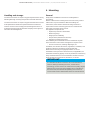
2 Transmitter overview
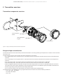
Transmitter components overview
Figure 1 - Gauge / absolute pressure transmitter components
Range and span consideration
The PGS and PAS Transmitter data sheet provides all information concerning the Range and Span limits in relation to the model and
the sensor code.
The terminology currently used to define the various parameters is as follows:
• URL: Upper Range Limit of a specific sensor. The highest value of the measured value that the transmitter can be adjusted to
measure.
• LRL: Lower Range Limit of a specific sensor. The lowest value of the measured value that the transmitter can be adjusted to
measure.
• URV: Upper Range Value. The highest value of the measured value to which the transmitter is calibrated.
• LRV: Lower Range Value. The lowest value of the measured value to which the transmitter is calibrated.
• SPAN: The algebraic difference between the Upper and Lower Range Values. The minimum span (MIN SPAN) is the minimum
value that can be used without degradation of the specified performance. The calibration span (CAL SPAN) is the difference
between Upper Range Value (URV) and Lower Range Value (LRV).
• TD: (or Turn Down Ratio) is the ratio between the maximum span and the calibrated span.
The transmitter can be calibrated with any range between the LRL and the URL with the following limitations:
– LRL ≤ LRV ≤ (URL - CAL SPAN)
– CAL SPAN ≥ MIN SPAN
– URV ≤ URL
HMI display with
keypad
Communication
board
Housing cover

8 PGS100 AND PAS100 | PRESSURE TRANSMITTERS | OI/PGS/PAS100-EN REV. A
3 Opening the box
Identification plates
The instrument is identified by the plates shown below.
Figure 2 - Nameplate for pressure transmitter model PGSxxx/PASxxx
The plate in figure 2 provides detailed information associated with the transmitter, concerning the model code, date of production,
hardware and software revisions, process wetted materials, power supply range, output signal, maximum working temperature
(TS) and pressure (PS), IP rating, PED identification code, range and span limits, calibration range and special request number (if
applicable) in another section.
Figure 3 - Additional Ex plate for devices intended for use in explosion risk areas
The certification plate in figure 3 provides details relevant to the hazardous area application of the transmitter, including as
applicable the markings and the relevant certificates, in association with the transmitter serial number and clear remarks to refer
to specific concerned documentation.
Figure 4 - Tag plate for pressure transmitter model PGSxxx/PASxxx
The tag plate in figure 4 is dedicated for detailing the tag number, the calibrated span as upper and lower range values with
associated engineering unit and the special request number, as applicable, if specified.
For information on the individual letters/numbers that make up the order code, please refer to the order confirmation or
associated data sheet. For information about labeling in accordance with the Pressure Equipment Directive, please
observe the information in “Compliance with Pressure Equipment Directive”.
The instrument may be used as a pressure accessory (category III) as defined by the Pressure Equipment Directive 2014/68/EU.
In this case you will find the number of the notified body (0474) that have verified the compliance. PGS and PAS pressure
transmitters are in compliance with EMC 2014/30/EU.
The certification plate is issued by ABB S.p.A, 22016 Tremezzina, Italy, with the numbers:
• Sira19ATEX2260X or IECEx SIR 19.0081X
CE-Identification number of the notified bodies to Pressure Equipment Directive: 0474, to ATEX certification: 0722, to IECEx
certification: IT/CES/QAR07.0001.
Figure 5 - 4-line layout of the optional wired-on Stainless Steel plate
QR Code
Serial Number : 3KXPxxxxxxxxxx
Model : PXS100 xxxxxxxxxxxxxxxx YYYYYYYYYYYYYYYYYYYYYYYYYYYYYYYY
Production Date : WW/YYYY
Process Connection : XXXXXXXX Pro. Conn. Material : XXXXXX Diaph. mat/Fill : xxxxxxx/ YYYYYYY
Supply Voltage xx...yy Vdc
LRL/URL -XXXXX ... +YYYYYY kPa Span limit XXXXX kPa
TS XXX °C PS XXX bar
Hw Rev. XX.YY.KK Sw Rev. XX.YY.KK
Output Signal 4...20 mA HART
IP xx Type 4X PED : XXXX
ABB S.p.A. Tremezzina (Co) Italy
Seal Model : xxxxxxxxxxxxxxxxx Seal Diaph/Fill : xxxxxxxxxxxxxx/ yyyyyyyyyyy
ABB S.p.A. Tremezzina (Co) Italy
Install per control drawing DH3275
II 1 G Ex ia IIC T4 Ga
II 1/2 D Ex ia IIIC T135°C Da/Db
Sira 19ATEX2260X
Serial Number : 3KXPxxxxxxxxxx
For entites see the certicate
Ex ia IIC T4 Ga
Ex ia IIIC T135°C Da/Db
IECEx SIR 19.0081X
II 1/2 D Ex ta/tb IIIC T135°C Da/Db
Ex ta/tb IIIC T135°C Da/Db
(-40°C<Tamb<+75°C or to +85°C See Manual)
Use only cable and cable gland with Temp rating > 85°C
Utilisez uniquement cables et conduit avec le Temp nom > 85°C
0474
0722
US C
!
IS/Sec Intrinseque (Entity)
CL I, Div 1, Gr ABCD T4 - CL II, Div 1, Gr E,F,G 120°C
CL III, DIV1
CSA20CA70192804X
CL I, Zone 0, AEx ia IIC T4 Ga / Ex ia IIC T4 Ga
Zone 20/21 AEx ia IIIC T135°C Da/Db / Ex ia IIIC T135 °C Da/Db
Zone 20/21 AEx ta/tb IIIC T135°C Da/Db
Ex ta/tb IIIC T135°C Da/Db
NOTICE
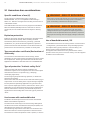
Optional wired-on plate
Models PGS and PAS transmitter can be supplied with the optional
“Wired On Stainless Steel plate” (figure 5) which is permanently
laser printed with a custom text specified in phase of order. The
available space consists in 4 lines with 32 characters per line.
The plate will be connected to the transmitter with a Stainless
Steel wire.

PGS100 AND PAS100 | PRESSURE TRANSMITTERS | OI/PGS/PAS100-EN REV. A
9
Handling and storage
The instrument does not require any special precautions during
handling although normal good practice should be observed.
The instrument does not require any special treatment if stored
as dispatched and within the specified ambient conditions.
There is no limit to the storage period, although the terms of
guarantee remain as agreed with the Company and as given in
the order acknowledgement.
4 Mounting
General
Study these installation instructions carefully before
proceeding.
Failure to observe the warnings and instructions may cause a
malfunction or personal hazard. Before installing the
transmitter, check whether the device design meets the
requirements of the measuring point from a measurement
technology and safety point of view.
This applies in respect of the:
• Explosion protection certification
• Measuring range
• Gauge pressure stability
• Temperature (Ambient and Process)
• Operating voltage and current
The suitability of the materials must be checked as regards
their resistance to the media. This applies in respect of the:
• Process connection, isolating diaphragm, etc.
In addition, the relevant directives, regulations, standards, and
accident prevention regulations must be observed.
Measurement accuracy is largely dependent on correct
installation of the pressure transmitter and, if applicable, the
associated measuring pipe(s). As far as possible, the measuring
setup should be free from critical ambient conditions such as
large variations in temperature, vibrations, or shocks.
If unfavorable ambient conditions cannot be avoided for
reasons relating to building structure, measurement
technology, or other issues, the measurement quality may be
affected. If a remote seal with capillary tube is installed on
the transmitter, the additional operating instructions for
remote seals and the related data sheets must be observed.
IMPORTANT

10 PGS100 AND PAS100 | PRESSURE TRANSMITTERS | OI/PGS/PAS100-EN REV. A
...4 Mounting
IP protection and designation
The housings for PGS and PAS transmitters are certified as
conforming to protection type IP67 / IP68 / IP69K (according to
ISO 20653) or NEMA 4X (according to NEMA 250).
The first number indicates the type of protection the
integrated electronics have against the entry of foreign bodies,
including dust.
“6” means that the housing is dust-proof (i.e., no ingress of
dust).
The second number indicates the type of protection the
housing has against the entry of water.
“7” means that the housing is protected against the effects of
temporary immersion in water under standardized water
pressure and temporal conditions.
“8” means that the housing is protected against the effects of
continuous immersion in water under 2 m water pressure and
30 minutes temporal conditions.
“9K” means that the housing is protected against the effects of
powerful high-temperature water jets under standardized
water pressure, temperature and temporal conditions.
The device and its accessories (i.e. cable glands and other
electrical connections) must be carefully and duly tightened to
meet expected IP protection type.
When using/mounting cable glands, they have to meet
expected IP rating.
Mounting the transmitter
Transmitter factory configuration consideration
The PGS and PAS pressure transmitter in your hands has been
factory calibrated to reflect the published declared
performance specification; no further calibration is required in
normal condition. ABB typically configures PGS and PAS
pressure transmitters according to the user requirements. A
typical configuration includes:
• TAG number
• Calibrated span
• Output linearization
• LCD display configuration
Hazardous area considerations
The transmitter must be installed in hazardous area only if it is
properly certified. The certification plate is permanently fixed
on the housing of the transmitter. Transmitter can have the
following certifications:
• ATEX Europe (code HAM) approval
• IECEx (code HJM) approval
• Combined CSA (code HCM) approvals (US and Canada)
• Combined ATEX Europe, IECEx, CSA (US and Canada)
approvals (code HMM)
For installations according to Canada and US Approvals, see
also control drawing DH3275.
See relevant paragraph for complete markings details.
Pressure Equipment Directive (PED)
(2014/68/EU)
Devices with PS >200
Devices with a permissible pressure PS >200 bar have been
subject to a conformity validation. The data label includes the
following specifications: Pressure Equipment Directive (PED)
(2014/68/EU).
Devices with PS ≤ 200
Devices with a permissible pressure PS ≤200 bar correspond
to article 4 paragraph 3. They have not been subject to a
conformity validation. These instruments were designed and
manufactured according to SEP Sound Engineering Practices.

PGS100 AND PAS100 | PRESSURE TRANSMITTERS | OI/PGS/PAS100-EN REV. A
11
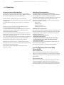
Mounting a P style pressure transmitter
A mounting bracket for wall or pipe mounting (2” pipe) is also available as an accessory.
Ideally, the pressure transmitter should be mounted in a vertical position to prevent subsequent zero shifts.
The pressure transmitter can also be mounted directly on the manifold.
If the transmitter is installed inclined with respect to the vertical, the filling liquid exerts hydrostatic pressure on the measuring
diaphragm, resulting in a zero shift. In such an event, the zero point can be corrected via the zero push-button or via the “set
PV to zero” command. Please refer to the [configuration section] for further details.
Figure 6 - Pipe and wall mounting bracket kits for P style transmitter
Sealing and screw connections
Connecting G ½ B spigot:
For sealing, a flat gasket must be used in accordance with DIN EN 837-1.
NPT threaded connection:
Seal the threads with PTFE or another approved resistant sealant.
Process connection with flush diaphragm:
Prior to mounting the device, install a welded connection or tapped hole according to relevant soldering standards (for process
connection and welded connection dimensions, refer to data sheet).
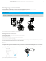
Moisture
Use suitable cables and tighten cable glands securely. The transmitter can also be protected against the ingress of moisture by
routing the connecting cable downward before securing it. This allows rain and condensation to drip down.
This is especially important for installation in outdoor areas and rooms that are exposed to moisture (e.g., due to cleaning
processes) or on cooled or heated tanks.
Figure 7 - Steps for preventing the ingress of moisture
IMPORTANT
SCALE 1:1
70 [2.76]
90 [3.55]
81.5 [3.21]
53 [2.09]
45 [1.77] 83 [3.27]
53 [2.09]
45 [1.77]
103 [4.06] 72.3 [2.85]

12
PGS100 AND PAS100 | PRESSURE TRANSMITTERS | OI/PGS/PAS100-EN REV. A
...4 Mounting
Measuring pipe
In order for the pipes to be laid correctly, the following points must be observed:
• Keep the measuring pipe as short as possible and avoid sharp bends.
• Lay the measuring pipe in such a way that no deposits can accumulate in it. Gradients should not be less than approx. 8 %
(ascending or descending).
• The measuring pipe should be blown through with compressed air or, better yet, flushed through with the measuring medium
before connection.
• Completely depressurize the measuring pipe if the medium is a fluid.
• Lay the measuring pipe in such a way that gas bubbles (when measuring fluids) or condensate (when measuring gases) can
flow back into the process line.
• When measuring steam, lay the measuring pipe in such a way that hot steam cannot flow back into the process connection
(water trap, e.g., a water trap pipe that is filled with water before installation).
• Check the tightness of the connection.

PGS100 AND PAS100 | PRESSURE TRANSMITTERS | OI/PGS/PAS100-EN REV. A
13
5 Transmitter wiring
General Risks.
Observe the applicable regulations governing electrical installation. Wiring must be executed in absence of power supply.
Before installing the device, check that the existing operating voltage corresponds to the power supply limits indicated on the
name plate.
Make sure to remove the power supply before connecting and/or disconnecting the device. High voltage that may be present on
terminals can cause electrical shock.
Since the device has no overvoltage or lightning protection inside, the installer have to use external protection to increase the
immunity level, if required.
Do NOT make electrical connections unless the electrical code designation stamped on the transmitter data plate agrees with
the classification of the area in which the transmitter is to be installed.
Failure to comply with this warning can result in fire or explosion.
Supply requirement
For signal/power connection use twisted, stranded pairs of wiring no 18 to 22 AWG / 0.8 to 0.35mm2 ø up to 5000 feet (1500
meters). Longer loops require larger wire.
If a shielded wire is used, the shield should be grounded only at one end, not both ends. In case of wiring at transmitter end,
use the terminal located inside the housing marked with the appropriate sign.
The 4 to 20 mA dc output signal and the dc power supply to the transmitter are carried from the same pairs of wires.
The transmitter operates from 10.5 to 42 V DC with no load and is protected against reverse polarity connection.
For Ex ia and other intrinsically safe approval power supply must not exceed 30 V DC.
Minimum operating voltage increase to 14.5 V DC with optional backlight LCD display.
For maximum power supply voltage please refer to the identification plate of the transmitter.
The actual possible line length of the electrical circuit depends on the total capacitance and resistance, and can be estimated using
the following formula:
Where:
L = Line length in m
R = Total line resistance in Ω (ohms)
C = Line capacitance in pF/m
Cf = Capacitance of the devices located in the circuit in pF
Avoid routing cables with other electrical cables (with inductive load, etc.) or near large electrical equipment.
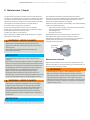
Cable connection
Depending on the variant selected, the electrical connection port is a standard threaded M16 x 1.5 entry.
Alternative threads ½ in - 14 NPT or M20 x 1.5 through adapter can be selected in the ordering information.
The screw terminals are suitable for wiring cross-sections up to 1.5 mm2 (16 AWG).
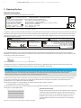
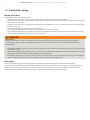
It is recommended that you strip approx. 30 to 35 mm (1.18 to 1.38 inch) off the cable jacket (see figure 8).
Use wiring rated 10 °C minimum above ambient temperature.
Figure 8 - Stripped connecting cable
Increased force will be required to unscrew the housing cover after an interval of several weeks. This is not caused by the threads,
but instead is due solely to the type of gasket.
WARNING
IMPORTANT
30 - 35 mm
1.18 - 1.38 inch
M10708

14 PGS100 AND PAS100 | PRESSURE TRANSMITTERS | OI/PGS/PAS100-EN REV. A
...5 Transmitter wiring
Wiring procedure
Follow these steps to wire the transmitter:
• Remove the temporary plastic cap from the electrical connection port of the transmitter housing.
• This connection port has an internal thread. Various adaptors and bushings can be fitted to these thread to comply with plant
wiring (conduit) standards.
• Remove the housing cover. In an Explosion-Proof/Flame-Proof installation, do not remove the transmitter covers when power
is applied to the unit.
• Run the cable through the cable gland and the open port.
• Connect the positive lead to the + terminal, and the negative lead to the – terminal.
• Plug and seal the electrical ports. Make sure that when the installation has been completed, the electrical ports are properly
sealed against entry of rain and/or corrosive vapors and gases.
General Risks.
Cable and cable gland must be in accordance with the intended type of protection (e.g. intrinsically safe) and degree of
protection (e.g. IP6x according to IEC EN 60529 or NEMA 4x). See also the addendum for “EX SAFETY” ASPECTS AND “IP”
PROTECTION.
• If applicable, install wiring with a drip loop. Arrange the drip loop so the bottom is lower than the conduit connections and the
transmitter housing.
• Before reassembling cover, the integrity of the cover O-ring must be checked. If damaged it must be replaced with an original
spare part. A slight grease layer should be applied for proper lubrication.
• Put back the housing cover, turn it to seat O-ring into the housing and then continue to hand tighten until the cover contacts
the housing metal-to-metal. The cover must be closed with a 30/35 Nm tightening torque.
Grounding
Pressure transmitter housing should be grounded or earthed in accordance with national and local electrical codes.
Protective grounding terminals (PE) are available outside and/or inside the housing of the transmitter. If ordered, both ground
terminals are electrically connected and it is up to the user to decide which one to use. The most effective transmitter case
grounding method is a direct connection to earth ground with impedance equal to or less than 5 ohm.
WARNING

PGS100 AND PAS100 | PRESSURE TRANSMITTERS | OI/PGS/PAS100-EN REV. A
15
-
+
+
-
-
internal earth terminal
power supply and
signal terminals
connector for LCD
communication board
power supply unit
resistor
line load
pushbutton for
0 (LRV setting)/
Span (URV setting) or
write protection
cable entry
handheld
terminal
optional
ground
receiver unit
SAFE AREAHAZARDOUS AREA
SEE INSTRUCTION MANUAL FOR CABLE
TEMPERATURE RATING
!
CAUTION
...5 Transmitter wiring
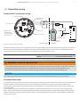
Output (HART) transmitter wiring
Figure 9 - Transmitter connection scheme
HART hand-held communicator may be connected at any wiring termination point in the loop, providing the minimum resistance is
250 ohm. If this is less than 250 ohm, additional resistance should be added to allow communications. The handheld terminal is
connected between the resistor and transmitter, not between the resistor and power source.
Application Permissible voltage range of power supply
Standard With optional backlit LCD display
Transmitter operated outside the potentially explosive atmosphere from 10.5 to 42 V from 14.5 to 42 V
Transmitter operated inside the potentially explosive atmosphere from 10.5 to 30 V max (intrinsically safe) from 14.5 to 30 V max (intrinsically safe)
If, when using transmitters with type of protection “intrinsic safety”, an ammeter is connected to the output circuit or a modem
is connected in parallel while there is a risk of explosion, the sums of the capacitances and inductances of all circuits, including
the transmitter (see EC-type-examination certificate) must be equal to or less than the permissible capacitances and
inductances of the intrinsically safe signal circuit (see EC-type-examination certificate for the power supply unit).
For CSA ordinary location, the maximum current must be limited to 150 mA by fuse (slow blow) or by a current limiter.
Communication setup
The transmitter can be operated via a HART modem, using a PC or laptop. The HART modem can be connected to the transmitter in
parallel at any point in the signal circuit. Communication between transmitter and modem occurs via FSK signals that are
superimposed on the analog 4 to 20 mA output signal. This modulation occurs without averaging, therefore does not affect the
measuring signal.
Communication between transmitter and PC or laptop is only possible if the signal circuit is set up as shown in the following
figure. The resistance between the connecting point for the FSK modem and the power supply must be at least 250 Ω (including
internal resistance of the power supply unit). If this value is not achieved within the context of normal installation, an additional
resistor must be used.
WARNING - RISK OF EXPLOSION
NOTICE

16
PGS100 AND PAS100 | PRESSURE TRANSMITTERS | OI/PGS/PAS100-EN REV. A
6 Commissioning
General remarks
Once the pressure transmitter has been installed, it is put into
operation by switching on the operating voltage.
Check the following before switching on the operating voltage:
• Process connections
• Electrical connection
• Fill the impulse line and measuring chamber of the
measuring cell completely with measuring medium.
The transmitter can then be put into operation.
To do this, the shut-off valves must be actuated in the following
order (in the default setting, all valves are closed):
1 Open the discharge shut-off valve, if present.
2 Open the shut-off valve.
To put the transmitter out of operation, carry out the steps in
reverse order.
In the case of pressure transmitters for absolute pressure
and measuring ranges of ≤ 40 kPa absolute, please note that
the pressure measuring cell has been overloaded over a long
period by the atmospheric pressure during transport and
storage. For this reason, you will need to allow a starting time
of approx. 3 hours after commissioning until the sensor has
stabilized to such an extent that the specified accuracy can
be maintained.
When using transmitters with ‘intrinsic safety’ type of
protection, if an ammeter is connected to the output circuit
or a modem is connected in parallel while an explosion hazard
is present, the sums of the capacitances and inductances of
all circuits, including the transmitter (see EC type
examination certificate) must be equal to or less than the
permissible capacitances and inductances of the intrinsically
safe signal circuit (see EC type examination certificate for the
power supply unit).
Only passive or explosion-proof test devices or display
instruments may be connected.
If the output signal stabilizes only slowly, it is likely that a
large damping time constant has been set on the transmitter.
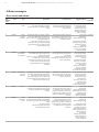
Output signal
If the applied pressure is within the values indicated on the
name plate, the analog output current ranges between 4 and
20 mA.
If the pressure applied falls outside the set range, the output
current will be driven as per defined configurations, as follows:
Output current limits for analog only version
Overload condition
Lower limit: 3.8 mA
Upper limit: 20.5 mA
Default alarm current: 21 mA
Output current limits for HART and analog version
(according to NAMUR NE 43 standard)
Overload condition
Lower limit: 3.8 mA (settable from 3.8 to 4 mA)
Upper limit: 20.5 mA (settable from 20 to 21 mA)
Alarm current
Lower alarm value: 3.6 mA (settable from 3.6 to 4 mA)
High alarm value: 21 mA (settable from 20 to 22.8 mA)
Default setting: high alarm current
NAMUR NE 43 defines as alarm limits the lower ≤ 3.6 mA and the
upper ≥ 21 mA.
Risk connected to any deviation from NAMUR NE43 thresholds
of the alarm current limits falls under Customers’ responsibility.
The graphical user interface (DD or FDI) can be used to
diagnose the error.
A brief interruption in the power supply results in
initialization of the electronics (program restarts).
Zero/Span and write protection
There is only one push button behind the display. It changes its
function depending on the presence of the display.
When the display is installed, it works as hardware write
protection switch. When the write protection is disabled, and
it is kept pressed for some 1 second, then the write protection
becomes enabled. In the opposite logic, when the write
protection is enabled, and the button is kept pressed, then the
write protection becomes disabled. This enable/disable
condition can be observed/confirmed by looking at the lock
symbol appearing or disappearing on the top line of the
display.
Write protection prevents the configuration/modification of
device data from being overwritten by unauthorized users. If
write protection is enabled, both local and remote writings are
refused. The Z (Zero) and S (Span) button cannot be used to set
new range values because their writing is disabled while their
use to enter and navigate into the local easy setup menu for the
read/review of the device parameter setting is still allowed.
However, when write protect is enabled, it is still possible to
read out the configuration data using graphical user interface
or communication tools (DD or FDI based).
Transmitter without display requires the communication tool to
activate write protection.
NOTICE
NOTICE

PGS100 AND PAS100 | PRESSURE TRANSMITTERS | OI/PGS/PAS100-EN REV. A
17
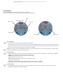
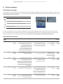
Local display
Local display features a LCD dot matrix for clear visualizations.
Here after a possible view according to selected transmitter configuration:
Row 1 displays:
• The HART short TAG, as a string of maximum 8 characters.
• The Lock symbol when either the local operation has been disabled or the device lock has been activated via relevant
HART commands or the write protection is enabled. The write protection is enabled by the push button present on the
electronics board and active only when LCD has been selected.
Row 2 is reserved to the value displayed with 5 digits, sign and decimal point, for one line visualization or with 8 digits,
sign and decimal point, for two lines visualization.
Row 3 displays:
• The ID of Variables, is a kind of acronym which identifies the variable currently displayed, with following possibilities.
– PDP Pressure value before transfer function/linearization
– ENG Measured value after transfer function (scaled output)
– OUT Analog current value in mA
– PV% Analog output current in percentage of calibrated range
– ST Sensor temperature
– HMI Measured value after dispaly scaling (HMI transfer function and scaling)
• The engineering unit code of the displayed measure. It can be anyone of HART list.
Row 4 displays:
• A bargraph additional to one-line or two-line value displayed that provides a different format of indication with
relevant percentage for a selectable variable.
Device TAG
Unit code
Bargraph
Variable IDs
Value
Bargraph %
Device protection

18 PGS100 AND PAS100 | PRESSURE TRANSMITTERS | OI/PGS/PAS100-EN REV. A
...6 Commissioning
Adjusting lower range value / oblique
sensors
During installation of the transmitter, zero position shifts may
occur due to the mounting position; these must be corrected.
Possible cause includes the transmitter mounting position
when different from recommended vertical mounting position.
The transmitter must have reached its operating temperature
(approx. 5 min. after startup, if the transmitter has already
reached the ambient temperature) in order to perform the
zero shift correction.
There are two options (variant A or B) for calibrating the
4 to 20 mA output signal directly on the transmitter.
Variant A, without LCD option by using the pushbutton on the
electronic board.
1 Make sure that the measured variable corresponds to the
lower range value for the measurement process, i.e., that the
pressure that the process exerts on the transmitter is the
level of pressure required to generate a 4 mA output signal.
The pressure must be stable (observe set damping level).
2 Unscrew the housing cover and press the pushbutton on the
electronic unit (see the above figure) using a pin with
diameter of ≤ 2.5 mm. Hold the pushbutton down for about
5/10 s. The output signal is set to 4 mA. The span remains
unchanged.
3 Make sure that the measured variable corresponds to the
upper range value for the measurement process, i.e., that the
pressure that the process exerts on the transmitter is the
level of pressure required to generate a 20 mA output signal.
The pressure must be stable (observe set damping level).
4 Press the pushbutton on the electronic unit (see the above
figure) using a pin with diameter of ≤ 2.5 mm. Hold the
pushbutton down for at least 15/20 s. The output signal is
set to 20 mA.
5 Screw the housing cover back on.
The procedure described in “A” above does not affect the
physical pressure shown; it only corrects the analog output
signal. For this reason, the analog output signal may differ
from the physical pressure shown on the digital display or the
communication tool.
To avoid this discrepancy, you need to correct the zero
position shift (zero shift) as described under variant “B”.
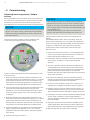
Variant B, with touchscreen controls on the optional LCD
display.
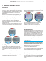
For PGS100/PAS100 models, when in operating mode, the
device shows respectively “Z-S” on the left and configuration
menu icon on the right side of the display. Pressing left button
for approx. 3 s leads to the sub-menu for Zero and Span,
showing letters Z and S respectively in the left and right
bottom corners.
1 Press the Z button for less than 5 s, on the display appears
the text “Do you want to proceed with Zero?” and the two
buttons change their meaning to Yes / No.
2 Pressing No, the “Zero” operation is aborted, while pressing
Yes the “Zero” operation is confirmed/accepted and
executed.
3 The “Zero” operation executed with this modality set the
“Lower Range Value” with the pressure value measured in
that instant while the “Upper Range Value” is shifted of the
same quantity maintaining the “Span”, as difference
between the Lower and Upper Range values, same as before
of the “Zero” operation.
4 As soon as the Yes button is pressed, and the operation
executed, in the bottom line of the display it appears for 5 s
a message relating the result of the operation.
5 In case of success it appears “Oper Done”, otherwise, it is
displayed one message describing the reason for failure.
6 Likewise, when you press the S button for less than 5 s, on
the display appears the text “Do you want to proceed with
Span?” and the two buttons change their meaning to Yes / No.
7 Pressing No, the “Span” operation is aborted, while pressing
Yes the “Span” operation is confirmed/accepted and
executed, displaying a feed-back of the result in the bottom
line of the display.
8 The “Span” operation executed with this modality set the
“Upper Range Value” with the pressure value measured in
that instant while the “Lower Range Value” is not changed.
9 With this operation the “Span” value is changed.
NOTICE
NOTICE

PGS100 AND PAS100 | PRESSURE TRANSMITTERS | OI/PGS/PAS100-EN REV. A
19
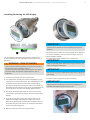
Installing/Removing the LCD display
The LCD display is attached to the electronic board of the
pressure transmitter. The LCD display can be replaced, e.g., if
defective.
The connection head can be become very hot as a result of
the process. There is a danger of burns.
Power off the transmitter before replacing the LCD display.
The transmitter atmosphere may be explosive. Risk of
explosion!
1 Unscrew the housing cover of the transmitter.
2 For replacement carefully remove the LCD display from the
inset connector of the transmitter. The LCD display just stay
in position on the electronic board and is firmly kept by
properly screwing the housing cover. Take care to avoid any
damage when removing the cover, due to possible detaching
of the LCD which can also cause the flat cable extension.
3 The length of the flat cable allows to carry out the wiring
connection to the terminals without disconnecting the LCD
display.
4 No tools are required to insert the LCD connector of the
replacement display. Carefully insert without forcing to
avoid wrong positioning and make sure the black connector
of the flat fits into the connector on the electronic board, as
shown in the following photo.
5 Make sure that the connector is fully inserted.
Carefully insert the flat connector following the required
polarity.
Following this, the position of the LCD display can be adjusted
to suit the installation position of the transmitter, to ensure
that the display is legible.
The LCD display can be rotated with increments of 5°.
Make sure the flat ribbon cable does not get twisted or torn
when rotating the LCD display.
Take care not to pinch the flat ribbon cable when rotating the
LCD display.
6 Screw on the housing cover for the transmitter.
Gently push the LCD display to ensure its positioning as
needed, while tightening the housing cover.
WARNING - RISK OF BURNS
IMPORTANT
IMPORTANT
IMPORTANT
IMPORTANT

20 PGS100 AND PAS100 | PRESSURE TRANSMITTERS | OI/PGS/PAS100-EN REV. A
...6 Commissioning
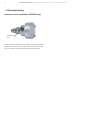
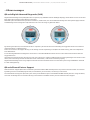
Pressure sensor ventilation (PGS100 only)
Transmitter has a reference port vented to the atmosphere and
duly protected. Care must be taken to avoid obstruction of the
port (i.e. covered, dirty) as it can affect the measurement.
Ventilation
port
Page is loading ...
Page is loading ...
Page is loading ...
Page is loading ...
Page is loading ...
Page is loading ...
Page is loading ...
Page is loading ...
Page is loading ...
Page is loading ...
Page is loading ...
Page is loading ...
-
 1
1
-
 2
2
-
 3
3
-
 4
4
-
 5
5
-
 6
6
-
 7
7
-
 8
8
-
 9
9
-
 10
10
-
 11
11
-
 12
12
-
 13
13
-
 14
14
-
 15
15
-
 16
16
-
 17
17
-
 18
18
-
 19
19
-
 20
20
-
 21
21
-
 22
22
-
 23
23
-
 24
24
-
 25
25
-
 26
26
-
 27
27
-
 28
28
-
 29
29
-
 30
30
-
 31
31
-
 32
32


ABB PGS100 Operating
- Category
- Measuring, testing & control
- Type
- Operating
- This manual is also suitable for
Ask a question and I''ll find the answer in the document
Finding information in a document is now easier with AI
Related papers
Other documents
-
 IFM Electronic efector150 Operating instructions
-
Omega PX633 Owner's manual
-
IFM NN5013 Operating instructions
-
IFM NF5030 Operating instructions
-
IFM NM500A Operating instructions
-
KILLARK CUP & PLUG Series Plugs Installation guide
-
Ashcroft F5510 Operating instructions
-
-
IFM SP321A Operating instructions
-
Pepperl+Fuchs HiC2871 User manual
