Page is loading ...

Conex
®
DIA-G
Gas warning controller
Installation and operating instructions
GRUNDFOS INSTRUCTIONS

English (GB)
2
English (GB) Installation and operating instructions
Original installation and operating instructions
CONTENTS
Page
1. Symbols used in this document
1. Symbols used in this document
2
2. Device settings
3
2.1 Sensor types
5
3. General information
5
4. Applications
5
5. Safety
6
5.1 Risks when safety instructions are not
observed
6
5.2 Obligations of the owner/operations
manager
6
5.3 Avoidance of danger
6
6. Identification
7
6.1 Nameplate
7
6.2 Type key, gas warning controllers
7
6.3 Type key, gas warning systems,
prepacked (with sensors and sensor
equipment)
8
7. Product description and accessories
9
7.1 General description
9
7.2 Dimensional sketches
11
8. Technical data
12
8.1 Signal inputs and outputs
13
8.2 Setting ranges for alarms / limit values
13
8.3 Sensors
13
8.4 Measuring and setting ranges
14
9. Installation
15
9.1 Transport
15
9.2 Intermediate storage
15
9.3 Unpacking
15
9.4 Installation requirements
15
9.5 Installation notes
15
9.6 Installation of the Conex
®
DIA-G
16
9.7 Assembling the Conex
®
DIA-G sensor
interface
17
10. Commissioning/electrical connections
17
10.1 Conex
®
DIA-G terminal assignment
18
10.2 Power supply connection
19
10.3 Connecting a backup battery
20
10.4 Relay outputs
20
10.5 Current output
20
10.6 Terminal assignment for Conex
®
DIA-G
sensor interface
21
10.7 Connection of sensors
22
11. Operation
25
11.1 Initial start-up
25
11.2 Control and display elements
26
11.3 Operating modes
26
11.4 Display elements during initial
commissioning
26
11.5 Operating instructions
27
11.6 Software overview
28
11.7 Main menu
33
11.8 Setup
33
11.9 Parameterising the sensors
39
11.10 Requesting settings in the service menu
43
11.11 Fine adjustment menu
45
11.12 Actions during operation
47
12. Error messages and fault finding
50
12.1 Error messages
50
12.2 Fault finding
51
13. Maintenance
52
14. Disposal
52
Warning
These complete installation and operating
instructions are also available on
www.grundfos.com.
Prior to installation, read these installation
and operating instructions. Installation and
operation must comply with local
regulations and accepted codes of good
practice.
Warning
If these safety instructions are not
observed, it may result in personal injury.
Caution
If these safety instructions are not
observed, it may result in malfunction or
damage to the equipment.
Note
Notes or instructions that make the job
easier and ensure safe operation.

English (GB)
3
2. Device settings
Note the key settings for the Conex
®
DIA-G.
Setup
Note
The set values can be stored in the "Setup
/ Factory setting" menu so that you can
access them again later.
Sensor 1
Off
Cl
2
sensor 91835237 (314-011)
Cl
2
sensor 96732268 (314-021)
ClO
2
sensor 95700837 (314-041)
ClO
2
sensor 91835237 (314-011)
O
3
sensor 95700838 (314-071)
O
3
sensor 96687714 (314-013)
HCl sensor 95700840 (314-061)
NH
3
sensor 95700839 (314-031)
Sensor 2
Off
Cl
2
sensor 91835237 (314-011)
Cl
2
sensor 96732268 (314-021)
ClO
2
sensor 95700837 (314-041)
ClO
2
sensor 91835237 (314-011)
O
3
sensor 95700838 (314-071)
O
3
sensor 96687714 (314-013)
HCl sensor 95700840 (314-061)
NH
3
sensor 95700839 (314-031)
Limit relay
Fail safe
On (N.C.)
Off (N.O.)
Confirm. LV 2
Yes
No
Alarm relay
Fail safe
On (NC)
Off (NO)
Confirmation
Yes
No
Alarm sensor 1
Limit value 1
On
Off
Limit value 2
On
Off
Test sensor
On
Off
Alarm sensor 2
Limit value 1
On
Off
Limit value 2
On
Off
Test sensor
On
Off

English (GB)
4
Sensor 1
Sensor 2
Current output
Sensor 1
0-20 mA
4-20 mA
Others:
Assignment
min. ppm =
mA
max. ppm =
mA
Current output
Sensor 2
0-20 mA
4-20 mA
Others:
Assignment
min. ppm =
mA
max. ppm =
mA
Auto. test S1
Off
On
days testing interval
Limit value 1
Off
On
ppm
Limit value 2
Off
On
ppm
sec delay
Limit value 1/2
ppm hysteresis
Alarm S1
Off
On
sec delay
Auto. test S2
Off
On
days testing interval
Limit value 1
Off
On
ppm
Limit value 2
Off
On
ppm
sec delay
Limit value 1/2
ppm hysteresis
Alarm S2
Off
On
sec delay

English (GB)
5
2.1 Sensor types
3. General information
These installation and operating instructions contain
all information important for users of the Conex
®
DIA-G gas warning controller.
• technical data
• instructions on commissioning, use and
maintenance
• safety information.
Should you require further information or should you
encounter problems that are not handled in sufficient
depth in this manual, please contact Grundfos Water
Treatment.
We shall be pleased to support you with our
comprehensive know-how in the fields of measuring
and control technology as well as water treatment.
We always welcome suggestions on how to optimise
our installation and operating instructions to satisfy
our customers.
4. Applications
The Conex
®
DIA-G gas warning controllers are used
to evaluate suitable sensors for monitoring the
concentration of chlorine (Cl
2
), chlorine dioxide
(ClO
2
), ozone (O
3
), ammonia (NH
3
) or hydrochloric
acid (HCl) and to trigger warning and protective
systems in the framework of the possible uses
described in this manual with the sensor types listed
here.
Sensor type
Measuring
parameter
Sensor
Amperometric
sensor (disc)
Cl
2
, ClO
2
91835237
(314-011)
O
3
96687714
(314-013)
Potentiostatic
sensor
Cl
2
96732268
(314-021)
NH
3
95700839
(314-031)
ClO
2
95700837
(314-041)
HCl
95700840
(314-061)
O
3
95700838
(314-071)
Caution
The Conex
®
DIA-G cannot be used for
measuring a gas concentration
continuously or for control according to the
German MAK standard regarding
maximum allowable concentration. Use
only calibrated gas measuring devices for
measuring gas concentration.
Ensure a sufficient safety level when
setting the limit values for the Conex
®
DIA-G.
Warning
Other applications are not approved and
not permitted. Grundfos cannot be held
liable for any damage resulting from
incorrect use.

English (GB)
6
5. Safety
This manual contains general instructions that must
be observed during installation, operation and
maintenance. This manual must therefore be read by
the installation engineer and the relevant qualified
personnel/operators prior to installation and start-up
and must be available at the installation location of
the Conex
®
DIA-G at all times.
It is not only the general safety instructions
described in this section 5. Safety that must be
observed, but all special safety instructions that are
provided in the other sections.
5.1 Risks when safety instructions are not
observed
If safety instructions are not observed, it may result
in personal injury or damage to the Conex
®
DIA-G. If
safety instructions are not observed, this may lead to
the loss of any claims for damages.
If individual safety instructions are not observed, this
may cause for example the following damage:
• failure of specified methods for recording gas
concentrations and secondary safety equipment
• harm to humans from exposure to electrical,
mechanical and chemical influences.
5.2 Obligations of the owner/operations
manager
The owner/operations manager must ensure that
persons working with the described device fulfil
these requirements:
• They are acquainted with the regulations
concerning working safety and accident
prevention.
• They have been trained in use of the device.
• They have read and understood the warning
information and handling symbols.
The owner/operations manager is also responsible
for ensuring that this manual is kept in the immediate
vicinity of the device and is always available for the
operating personnel and that the local safety
regulations are observed when setting the limit
values for the sensors.
5.3 Avoidance of danger
5.3.1 Safety instructions for the operator
Damage caused by electrical energy must be
prevented. For more details, see for example the
regulations of the VDE, German Association for
Electrical, Electronic and Information Technologies,
and the local power supply company.
5.3.2 Safety instructions for maintenance,
inspection and installation work
The operator is responsible for ensuring that all
maintenance, inspection and installation work is
carried out by authorised and qualified personnel,
who have been adequately trained by reading the
installation and operating instructions.
All safety and protective equipment must be
immediately restarted or put into operation once
work is complete.
Observe the points described in the initial start-up
section prior to subsequent start-up.
Warning
Do not use the device for monitoring
constant concentrations. The device is
designed for detecting leaks.
Warning
Installation and connection of the device
and the associated supplementary
components must only be carried out by
qualified specialists!
The local safety regulations must be
observed!
Warning
Switch off the power supply before
connecting the power supply cable and
relay contacts!
Do not dismantle the device! Maintenance
and repairs must only be carried out by
authorised specialists!
Caution
The mounting location must be selected so
that the housing is not subjected to
mechanical loading.
Check that all settings are correct before
starting up the device!

English (GB)
7
6. Identification
6.1 Nameplate
Fig. 1 Nameplate, Conex
®
DIA-G
6.2 Type key, gas warning controllers
Example: DIA-G, 1-D/A/HC 2-D/A/HC, W-J
TM04 1259 0509
DIA-G, 1-D/A/HC 2-D/A/HC, W-J
308-2000-10012
S/N: 08/11221
Conex DIA-G
110-240V 50/60Hz 24V/DC, 30 VA,
IP 65
96732266P1108060808565
1
2
3
4
5
7
8
9
10
11
12
6
Pos. Description
1 Type designation
2 Model
3 Product
4 Voltage [V]
5 Frequency [Hz]
6 Product number
7 Country of origin
8 Year and week of production
9 Marks of approval, CE mark, etc.
10 Power consumption [VA]
11 Enclosure class
12 Serial number
Example: DIA-G 1-D/A/HC 2-D/A/HC W -J
Conex
®
gas warning system
DIA-G
Dosing Instrumentation Advanced with gas
detection
Sensor 1
D Chlorine gas/chlorine dioxide gas/ozone gas
A Ammonia gas
HC Hydrochloric acid gas
Sensor 2
D Chlorine gas/chlorine dioxide gas/ozone gas
A Ammonia gas
HC Hydrochloric acid gas
Mounting
W Wall-mounted
P Panel-mounted
Voltage
G 1 x 230/240 V, 50/60 Hz
H 1 x 115/120 V, 50/60 Hz
J 110-240 V, 50/60 Hz, 24 VDC

English (GB)
8
6.3 Type key, gas warning systems, prepacked (with sensors and sensor equipment)
Example: DIA-G-P, CLP-OP-B, W-J
Example: DIA-G -P. CLP- OP- B. W -J
Conex
®
gas warning system
DIA-G Dosing Instrumentation Advanced with gas detection
PPrepacked
Sensor 1
CCA Chlorine gas/chlorine dioxide gas, amperometric measurement
OA Ozone gas, amperometric measurement
CLP Chlorine gas, potentiostatic measurement
CDP Chlorine dioxide gas, potentiostatic measurement
OP Ozone gas, potentiostatic measurement
AP Ammonia gas, potentiostatic measurement
HCP Hydrochloric acid gas, potentiostatic measurement
Sensor 2
CCA Chlorine gas/chlorine dioxide gas, amperometric measurement
OA Ozone gas, amperometric measurement
CLP Chlorine gas, potentiostatic measurement
CDP Chlorine dioxide gas, potentiostatic measurement
OP Ozone gas, potentiostatic measurement
AP Ammonia gas, potentiostatic measurement
HCP Hydrochloric acid gas, potentiostatic measurement
Option
B Battery backup
X No battery backup
Mounting
W Wall-mounted
P Panel-mounted (not available at the moment)
Voltage
G 1 x 230/240 V, 50/60 Hz
H 1 x 115/120 V, 50/60Hz
J 110-240 V, 50/60 Hz, 24 VDC

English (GB)
9
7. Product description and
accessories
This universal device offers high-precision
measuring of chlorine, chlorine dioxide, ozone,
ammonia or hydrochloric acid.
• comprehensive limit value functions
• comprehensive alarm functions
• logbook function: chronological recording of key
events with date and time
• user coding function as a means of protection
against access by unauthorised persons and for
system administration
• error message function for indication of
non-functioning sensors
• automatic monitoring of the sensor service life
with warnings about sensors that require
renewal.
7.1 General description
The Conex
®
DIA-G is a gas warning controller for
monitoring gas concentrations, for example in
storage or dosing rooms. With a maximum of two
independently connected sensors, the gas
concentration of chlorine, ozone, chlorine dioxide,
hydrochloric acid or ammonia can be displayed and
monitored. Amperometric sensors (sensor discs) can
be connected directly to the Conex
®
DIA-G, and
potentiostatic sensors can be connected to a
preceding Conex
®
DIA-G sensor interface.
Each of the two sensors is provided with electrically
isolated current outputs (potential-free to power
supply) to output the measured concentration, two
electrically isolated limit value transmitters and an
alarm relay to control the warning and safety
equipment.
The Conex
®
DIA-G meets the high safety
requirements through permanent sensor monitoring,
alarm relays and optional backup mode (connection
of an external backup battery for supplying power to
the Conex
®
DIA-G in case of short-term power
supply interruptions).
How the system operates
• The gas sensors generate a current which is
proportional to the gas concentration in the air.
• The Conex
®
DIA-G gas warning controller
– amplifies the sensor current
– triggers an initial warning, for example when
the first limit value is exceeded
– activates the relevant warning and safety
equipment when the second limit value is
exceeded
– outputs the measured concentration at both
sensors as a 0 (4) - 20 mA signal via the
current outputs (for example for recording).

English (GB)
10
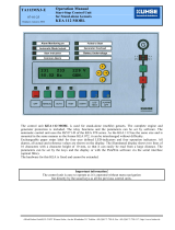
Fig. 2 Gas warning system
The complete gas warning system comprises:
• gas sensors in the gas container and gas dosing unit area
• the Conex
®
DIA-G gas warning controller
• warning and safety equipment: horn, flashing warning system, sprinkling installation.
TM03 7022 4506
4
6
5
7
3
2
1b
1a
Conex DIA-G
Sensor 1
Sensor 2
OKEsc
Alarm
Pos. Description
1a Amperometric gas sensor
1b Potentiostatic gas sensor with Conex
®
DIA-G sensor interface
2 Gas container
3 Gas dosing unit
4 Conex
®
DIA-G gas warning controller
5Horn
6 Flashing warning system
7 Sprinkling installation

English (GB)
11
7.2 Dimensional sketches
Fig. 3 Conex
®
DIA-G
Fig. 4 Conex
®
DIA-G sensor interface
TM03 7023 4506
59
125
84
59.5
184.5
212
198
10
145
27
99
Ø 4.5
TM03 7024 4506
120
146.5
101.5
80
42

English (GB)
12
8. Technical data
Caution
Observe the permissible temperature range of the sensors!
Note
Observe the accuracy of the sensor!
Electronics 16-bit microprocessor technology
Display Backlit plain-text display
Display languages German, English, French, Spanish, Russian and Polish
Indication mode In ppm for measured values of both sensors
Permissible temperatures
Conex
®
DIA-G and sensor interface (without sensor):
• operation: 0 to +40 °C
• storage: 0 to +65 °C
Permissible relative air
humidity
Maximum 90 % at 40 °C (no condensation)
Power supply
• 110-240 V - 10 %/+ 10 % (50/60 Hz)
• 24 VDC
Power consumption Approximately 30 VA
Material (enclosure) ABS, resistant to chemicals
Enclosure class IP65 for Conex
®
DIA-G wall-mounting enclosure and sensor interface
Weight Approximately 1.5 kg
Connections Screw terminals for cables up to maximum 2.5 mm
2
Safety functions
• Permanent sensor monitoring or automatic sensor test, interval between
tests adjustable from 0.5 to 30 days
• Wire breakage monitoring of all current outputs
• Optional backup battery with backup indication on the display, allowing
Conex
®
DIA-G to work for at least one hour after power failure
• Automatic adjustment of data specific to the sensor (for example
calibration data)
• Display of the sensor exchange intervals with a plain-text message
Backup battery
All devices can be equipped with an external backup battery as an option.
The backup battery supplies the gas warning controller, including the
electrically isolated relays, but no external devices (for example signal
lamp, aeration, sprinkler system, etc.). The battery lasts for about one hour
after power supply failure.

English (GB)
13
8.1 Signal inputs and outputs
8.2 Setting ranges for alarms / limit values
8.3 Sensors
Amperometric sensor disc Cl
2
, ClO
2
and O
3
Connection via 2-wire cable 0.5 mm
2
with single
screen. Maximum length (maximum distance
between the sensor disc and gas warning controller):
100 metres.
91835237 (314-011)/96687714 (314-013) include the
wall housing with sensor disc.
Potentiostatic sensor Cl
2
, ClO
2
, O
3
, NH
3
, HCl
The sensor is plugged directly into the interface. The
interface is connected to the gas warning controller
using a 4-wire cable with single screening (special
cable for CAN connections). Maximum length
(maximum distance between Conex
®
DIA-G sensor
interface and gas warning controller): 500 metres.
Relay outputs
Five potential-free relay outputs, switchable to NO (normally open) or NC (normally
closed) (fail safe); maximum 250 V / 6 A, maximum 550 VA ohmic load:
• two relays for the limit values of each of the two sensors
• one alarm relay; free assignment to the limit values or to sensor test (see below)
Signal inputs
• Two measured value inputs (for amperometric sensors 1 and 2)
• Internal CANBus, including connections for two sensor interfaces, each for the
operation of one potentiostatic sensor
Signal outputs
Two potential-free current outputs (0) 4 - 20 mA, maximum load of 500 Ω, with cable
breakage monitoring; assignment of 0 (4) - 20 mA to the measuring range of the
selected sensor, or linear assignment of the current output (0-20 mA) to the
measuring value (within the measuring range of the selected sensor)
Switching point for
limit values
• Limit value 1 (warning if exceeded) can be set to any value within the measuring
range.
• Limit value 2 (warning if exceeded) can be set to any value within the measuring
range.
• Limit value 2 can be delayed between 0-180 seconds.
• Hysteresis: 0-50 % of measuring range.
• Limit value 1 and 2 can be acknowledged. The acknowledgement is stored in a
list of events.
Alarm relay
• The alarm relay can be freely assigned to the limit values and/or the sensor test.
• The alarm can be delayed between 0-180 seconds.

English (GB)
14
8.4 Measuring and setting ranges
8.4.1 Measuring parameter and working range for amperometric sensors
8.4.2 Measuring parameter and working range for potentiostatic sensors
Measuring parameter Measuring range Accuracy Temperature range Product number
[ppm] [%] [°C]
Cl
2
, ClO
2
0.00 - 5.00 ± 10 +5 to +45
91835237
(314-011)
O
3
0.00 - 5.00 ± 10 +5 to +45
96687714
(314-013)
Measuring
parameter
Measuring
range
Resolution
at 20 °C
Linearity
Sensitivity drift
per 6 months
Temperature
range
Product
number
[ppm] [ppm]
[%] of full
scale
[%] [°C]
Cl
2
0.00 - 20.00 < 0.05 < 5 < 10 -20 to +40
96732268
(314-021)
NH
3
0 - 100 < 1 < 10 < 5 -20 to +40
95700839
(314-031)
ClO
2
0.00 - 1.00 < 0.03 < 10 < 10 -20 to +40
95700837
(314-041)
HCl 0.0 - 30.0 < 0.7 < 5 < 3 -20 to +40
95700840
(314-061)
O
3
0.00 - 1.00 < 0.02 < 10 < 10 -20 to +40
95700838
(314-071)
Note
The measuring ranges depend on the set sensors and cannot be modified.

English (GB)
15
9. Installation
9.1 Transport
9.1.1 Delivery
The Conex
®
DIA-G is delivered in a cardboard box.
Leave the device in the packaging during transport
and intermediate storage.
9.1.2 Return
Return the Conex
®
DIA-G in its original packaging or
equivalent.
9.2 Intermediate storage
Permissible storage temperature: -20 °C to +65 °C.
9.3 Unpacking
1. Check the device for damage. Install as soon as
possible after unpacking.
2. Do not install or connect damaged devices!
9.4 Installation requirements
Conex
®
DIA-G
• Dry room
• Room temperature: 0 °C to +40 °C
• Vibration-free location.
Sensors
• Dry room.
– Avoid the sensor getting wet! Make sure to
locate it outside the range of the sprinkling
installation.
• Room temperature according to the technical
data for the relevant sensor.
• Vibration-free location.
• Protect the sensor from direct heat, sunlight and
strong draughts!
9.5 Installation notes
Amperometric sensor discs are connected directly to
the Conex
®
DIA-G. If potentiostatic sensors are
used, one Conex
®
DIA-G sensor interface per
sensor is required.
Maximum cable lengths:
• Amperometric sensors: 100 metres
• DIA-G sensor interface for potentiostatic sensors
(CANBus connection): 500 metres.
Warning
Before assembling, disconnect the power
supply!
Enclosure class IP65 is only guaranteed if
the terminal covers are closed and the
appropriate cable glands or dummy caps
fitted.
Caution
Risk of malfunction or damage to the
Conex
®
DIA-G! Do not drop the device.
Caution
Risk of malfunction or damage to the
Conex
®
DIA-G! Grundfos accepts no
liability for damage caused by incorrect
transportation or missing or unsuitable
packaging of the device!
Note
For information on storing the sensors, see
the manual of the gas sensors.
Note
Retain the packing material or dispose of it
according to local regulations.
Caution
The sensor must be replaced after a gas
eruption that has exceeded the measuring
range. Do not expose the sensor to a
higher gas concentration, even during
start-up and test.
Caution
Gas sensors should not be mounted close
to major sources of interference such as
large machines, etc.
Caution
If these assembly requirements are not
observed, there may be damage to the
measuring device or incorrect
measurements!

English (GB)
16
9.6 Installation of the Conex
®
DIA-G
1. Drill three holes (∅8 mm) as shown in the
diagram, and insert the supplied dowels.
2. Unscrew the terminal cover on the device.
3. Tighten the upper middle screw (A).
4. Place the device on this screw (A).
5. Secure the device through the enclosure using
the two other screws (B).
6. Replace the terminal cover.
Fig. 5 Drilling diagram of the Conex
®
DIA-G
Fig. 6 Mounting drawing
Warning
Switch off the power supply before
installing!
Enclosure class IP65 is only guaranteed if
the terminal covers are closed and the
appropriate cable glands or dummy caps
fitted.
Caution
Enclosure class IP65 is only guaranteed if
the terminal cover is correctly sealed!
Do not damage the terminal cover gasket!
The terminal cover gasket must fit exactly!
TM03 7025 4506
198
145
27
10.5
99
TM03 7026 4506
B
B
A
Conex DIA-G
Sensor 1
Sensor 2
OKEsc
Alarm

English (GB)
17
9.7 Assembling the Conex
®
DIA-G sensor
interface
If potentiostatic sensors are used, a separate
Conex
®
DIA-G sensor interface must be installed.
1. Drill four holes (∅6 mm) as shown in the
diagram, and insert the supplied dowels.
Fig. 7 Drilling diagram of Conex
®
DIA-G
sensor interface
2. Unscrew the device cover.
3. Secure the device with the four supplied screws.
4. Replace the device cover.
10. Commissioning/electrical
connections
1. Remove the terminal cover on the front of the
device.
2. Use the appropriate cable entries, and tighten the
screws carefully.
3. Connect the cables used to the terminals
according to the Conex
®
DIA-G terminal
assignment.
4. Close the terminal cover again with correctly
positioned gasket.
Warning
Switch off the power supply before
installing!
Enclosure class IP65 is only guaranteed if
the terminal covers are closed and the
appropriate cable glands or dummy caps
fitted.
TM03 7027 4506
Caution
Enclosure class IP65 is only guaranteed if
the terminal cover is correctly sealed!
Do not damage the terminal cover gasket!
The terminal cover gasket must fit exactly!
108
6
15
50
Warning
Switch off the power supply before
installing!
Enclosure class IP65 is only guaranteed
with the front panel of the terminals
enclosure closed and with appropriate
cable glands or dummy caps.
Warning
Disconnect the power supply before
connecting the power supply cable and the
relay contacts! For safety reasons, the
protective conductor must be connected
correctly!
Observe the local safety regulations!
Protect the cable connections and plugs
against corrosion and humidity.
Caution
Before connecting the power supply cable,
check that the supply voltage specified on
the nameplate corresponds to the local
conditions!
An incorrect supply voltage may destroy
the device!
To guarantee electromagnetic compatibility
(EMC), the input and current output cables
must be screened.
Connect the screening to the screen
ground on one side!
Refer to the wiring diagram! Route the
input, current output and power supply
cables in separate cable channels.
Caution
Enclosure class IP65 is only guaranteed if
the terminal cover is correctly sealed! Do
not damage the gasket on the terminal
cover!
The terminal cover gasket must fit exactly!
Note
Unused terminals must remain open.

English (GB)
18
10.1 Conex
®
DIA-G terminal assignment
Fig. 8 Conex
®
DIA-G terminal
Key for Conex
®
DIA-G terminal diagram
TM04 8396 1411
1
S1
0
1
S2
0
Main in
Sensor 1
SP2
Sensor 2
SP2
Alarm
Input
Bat
24 V
CAN
Sensor
CAN
Interface
Reset
mAmA
Sensor 1
out SP1SP1
NO
NC
24V Out
Sensor
Interface
Bat
ok
mAmA
Sensor 2
+
+++++
+
–
+
––
–––––
LL
LL
HH
HH
LNPE
LNPE
12
12
1
2
3
4
5
6
7
8
9
10
11
12
13
14
15
16
17
18
19
20
21
22
23
24
25
26
27
28
29
30
31
32
33
34
35
36
37
38
39
40
41
42
43
44
45
46
47
48
49
50
Assignment Terminal Description
Main in
L1
Power supply connectionN3
PE 5
Main out
L2
Supply for electrically isolated contactsN4
PE 6
Sensor 1/SP 1 7, 8 Limit value relay (setpoint) 1, sensor 1
Sensor 1/SP 2 9, 10 Limit value relay (setpoint) 2, sensor 1
Sensor 2/SP 1 11, 12 Limit value relay (setpoint) 1, sensor 2
Sensor 2/SP 2 13, 14 Limit value relay (setpoint) 2, sensor 2
Alarm
NO 18
Alarm relay with terminal 15, 16 and terminal 18:
normally open contact, or terminal 17: normally
closed contact
NC 17
15, 16
Input Bat
24 V
+19
Input for external battery supply (UPS)
-20
24 V Out Sensor
Interface
+21
24 V supply output for sensor interface
-22
CAN sensor
(sensor interface
connection)
L 23, 24 Terminal 23: input... or terminal 24: output...
H 25, 26 Terminal 25: input... or terminal 26: output...
Screen
27, 28 Terminal 27: input... or terminal 28: output...
CAN interface
(CANBus
connection)
L 29, 30 Terminal 29: input... or terminal 30: output...
H 31, 32 Terminal 31: input... or terminal 32: output...
Screen
33, 34 Terminal 33: input... or terminal 34: output...
Reset
+35
External alarm acknowledgement using switching
contact
-36

English (GB)
19
10.2 Power supply connection
Voltage supply for Conex
®
DIA-G at 110-240 V:
• Connect the protective conductor (PE) to terminal
5.
• Connect the neutral conductor (N) to terminal 3.
• Connect the phase (L1) to terminal 1.
Voltage supply for Conex
®
DIA-G at 24 VDC:
• Connect + to terminal 19.
• Connect - to terminal 20.
Voltage supply for electrically isolated relay
contacts:
• Connect the protective conductor (PE) to terminal
6.
• Connect the neutral conductor (N) to terminal 4.
• Connect the phase (L1) to terminal 2.
Bat ok
+37
Battery backup: working
-38
mA
+39
Analog output sensor 1
-40
Screen
43
mA
+41
Analog output sensor 25
-42
Screen
44
Sensor 1
-45
Connection for amperometric sensor 1
Screen
47
+49
Sensor 2
-46
Connection for amperometric sensor 2
Screen
48
+50
S1
Selection switch for sensor interface termination
resistor
1 Position 1: On
0 Position 0: Off
S2
Selection switch for CAN interface termination
resistor
1 Position 1: On
0 Position 0: Off
Assignment Terminal Description
Caution
Before connecting, check that the values
for the supply voltage and frequency
correspond to the values on the
nameplate.
Note
Switch the device on and off by switching
the power supply on and off accordingly.
The device itself is not equipped with a
separate on/off switch.

English (GB)
20
10.3 Connecting a backup battery
Voltage supply via backup battery:
• Connect + to terminal 19.
• Connect - to terminal 20.
Backup battery monitoring function:
• Connect + to terminal 37.
• Connect - to terminal 38.
10.4 Relay outputs
With inductive loads (including relays and
contactors), interference suppression is necessary.
If this is not possible, protect the relay contacts using
a suppressor circuit as described below.
• With AC voltage:
• With DC voltage: Connect the free-wheeling
diode in parallel to relay or contactor.
Fig. 9 Suppressor circuit DC/AC
10.5 Current output
The current output can be set to one of the two
standard ranges "0-20 mA" or "4-20 mA", or it can be
freely adjusted.
• Connect the screen to earth (PE) at one end.
Output 1: sensor 1
This current output emits the displayed measured
value as an analog current signal.
Use of current signal for measured values:
• As input signal for another indicator.
1. Connect the + conductor to terminal 39.
2. Connect the - conductor to terminal 40.
Output 2: sensor 2
This current output emits the displayed measured
value as an analog current signal.
Use of current signal for measured values:
• As input signal for another indicator
1. Connect the + conductor to terminal 41.
2. Connect the - conductor to terminal 42.
Note
The connection of the relay outputs
depends on the application and the final
control elements used.
Therefore the connections described
below should only be considered as
guidelines.
Current up to Capacitor C Resistor R
60 mA 10 μF, 275 V 390 Ω 2 W
70 mA 47 μF, 275 V 22 Ω, 2 W
150 mA 100 μF, 275 V 47 Ω, 2 W
1.0 A 220 μF, 275 V 47 Ω, 2 W
Caution
Provide the relay outputs with a
corresponding backup fuse!
TM03 7209 2813
+
-
DC
R
C
AC
Caution
Ensure correct polarity! Maximum load:
500 Ω.
/