Page is loading ...

Conex
®
DIS-2Q
Installation and operating instructions
GRUNDFOS INSTRUCTIONS

English (GB)
2
English (GB) Installation and operating instructions
Original installation and operating instructions.
CONTENTS
Page
1. Symbols used in this document
1. Symbols used in this document
2
2. Parameter settings
3
3. General information
4
4. Applications
4
5. Safety instructions
4
5.1 Obligations of the owner
4
5.2 Avoiding danger
4
6. Identification
4
6.1 Nameplate
4
7. Technical data
4
7.1 Enclosure class
4
7.2 General data
5
7.3 Electronic data and functions
5
7.4 RS-485 interface
6
7.5 Dimensions
6
8. Installation
6
8.1 Transport and storage
6
8.2 Unpacking
6
8.3 Installation requirements
6
8.4 Installation in control panel
6
8.5 Installation in wall housing
7
9. Electrical connection
7
9.1 Terminals
8
9.2 Power supply connection
9
9.3 Current inputs and outputs
9
9.4 Feedback potentiometer of the final
control element
9
9.5 Relay outputs
10
10. Operation
11
10.1 Function
11
10.2 Controls and displays
13
10.3 Operating the controller
14
11. Fault finding
26
12. Maintenance
26
12.1 Replacing mains fuses (wall housing)
26
13. Spare parts
26
14. Disposal
26
15. Appendix
27
15.1 Measuring and control technology
27
15.2 Application examples of different output
signals and final control elements
34
15.3 RS-485 serial interface
58
Warning
Prior to installation, read these
installation and operating instructions.
Installation and operation must comply
with local regulations and accepted
codes of good practice.
Warning
These complete installation and
operating instructions are also
available on www.grundfos.com.
Prior to installation, read these
installation and operating instructions.
Installation and operation must comply
with local regulations and accepted
codes of good practice.
Warning
If these safety instructions are not
observed, it may result in personal
injury.
Caution
If these safety instructions are not
observed, it may result in malfunction
or damage to the equipment.
Note
Notes or instructions that make the job
easier and ensure safe operation.

English (GB)
3
2. Parameter settings
Controller settings
LED 1st level 2nd level 3rd level
M
Measured value Code functions
--- %
Code
Code number Hysteresis Device number for RS-485
--- %
SP 1
Switching point SP 1 Pulse frequency for SP 1 Transmits alarm via RS-485
%
x 100
pulses/
hour
01 (yes)
00 (no)
SP 2
Switching point SP 2 Pulse frequency for SP 2
%
x 100
pulses/
hour
XP
Proportional band Xp Interpulse period
%sec
TN (s)
Reset time Tn Actuating time
sec sec
TV (s)
Derivative action time Tv Disturbance variable Range of current input 2
sec --- %
% at 0 (4) mA
% at 20 mA
TM03 7053 2108
Position of feedback
potentiometer
--- %
TM03 7054 2108
Maximum dosing time Minimum pulse length
sec sec

English (GB)
4
3. General information
This manual contains all important information about
the Conex DIS-2Q:
• technical data
• instructions for startup, use and maintenance
• safety information.
If you need further information, or if problems occur
which are not described in details in this manual,
please contact Grundfos.
4. Applications
The Conex DIS-2Q is a multipurpose device
designed to carry out high-precision controls of
disinfection parameters, pH-value and redox
potential.
Conex DIS-2Q microprocessor-based controllers
controls any measured variables using appropriate
final control elements.
5. Safety instructions
5.1 Obligations of the owner
The owner of the plant is responsible for:
• compliance with country-specific safety
regulations
• training of operating personnel
• provision of prescribed protective equipment
• implementation of regular maintenance.
5.2 Avoiding danger
6. Identification
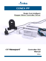
6.1 Nameplate
Fig. 1 Nameplate, Conex DIS-2Q
7. Technical data
7.1 Enclosure class
Warning
Other applications than those
described in section 4. Applications
are considered as non-approved and
are not permissible.
Grundfos cannot be held liable for any
damage resulting from incorrect use.
Warning
Installation and connection of the
device and the associated
supplementary components must only
be carried out by authorised personnel!
The local safety regulations must be
observed!
Warning
Switch off the power supply before
connecting the power supply cable and
relay contacts!
Do not open the device!
Maintenance and repair must only be
carried out by authorised personnel!
Caution
Select the mounting location so that
the housing is not subject to
mechanical loading.
Check that all settings are correct
before starting the device!
TM04 1218 1213
Pos. Description
1 Model
2 Serial number
3 Voltage [V]
4 Frequency [Hz]
5 Product name
6 Product number
7 Country of origin
8 Year and week of production
9CE mark
10 Power consumption [VA]
11 Enclosure class
Control panel enclosure IP54 (front)
Control panel enclosure
with optional front door
IP55
Wall-mounted enclosure
(optional wall housing)
IP65
342-5000-10000
S/N: 08/61557
230/240V 50/60Hz 8 VA, IP 65
Conex DIS-2Q
96732494P1108270861557
1
3
4
789
10
11
6
2
5

English (GB)
5
7.2 General data
7.3 Electronic data and functions
7.3.1 Inputs and outputs
7.3.2 Controller functions
7.3.3 Display ranges
7.3.4 Adjustment ranges
Input power Approximately 8 VA
Permissible
ambient
temperature
0 to 50 °C
Permissible
storage
temperature
-20 to +65 °C
Maximum relative
humidity
90 % (non-condensing)
Weight 0.8 kg
Enclosure Noryl, chemically resistant
Connections
Screw-plug terminals for
cables up to 2.5 mm
2
Versions of power
supply
• 230/240 V (50/60 Hz)
(standard model)
• 115/120 V (50/60 Hz)
Current output 1
Continuous control output for
SP 1:
• 0 (4) to 20 mA
• electrically isolated
• max. load 400 Ω.
Current output 2
Position of feedback
potentiometer or continuous
control output for SP 2
• 0 (4) to 20 mA
• electrically isolated
• max. load 400 Ω.
Current input 1
Measured value (actual
value):
• 0 (4) to 20 mA
• electrically isolated
• load 50 Ω.
Current input 2
Disturbance variable/
command variable:
• 0 (4) to 20 mA
• electrically isolated
• load 50 Ω.
Contact rating
6 A / 250 V, max. 550 VA
resistive load (with contact
protection circuit) of relay
outputs.
Note
The current inputs are electrically
isolated from the current outputs, but
are applied together to the same
potential.
Control functions
• Limit contact
• continuous controller
• two-position controller
• three-position controller
proportional controller
• ratio controller
• controller with disturbance
variable feedforward.
Control action
• Proportional action
• integral action
• differential action.
Measured value (actual value) 0-100 %
Disturbance variable 0-1,999 %
Position of final control element 0-100 %
Switching points 0-100 %
Control direction
Can be set to upward or
downward.
Proportional band X
p
0-500 %
Reset time T
n
0-1,999 s
Derivative action time
T
v
0-500 s
Setting for current
output 2
Ratio: -1,999 to +1,999 %
Disturbance variable:
0-1,999 %
Hysteresis 0-50 %
Interpulse period 1-99 s
Minimum pulse width 0 - 9.9 s
Pulse frequency
(selectable
separately for each
switching point)
0.1 - 72 (correlates with
10-7,200 pulses/hour)
Actuating time 1-240 s
Time delay for alarm
signal
0-1,999 s (maximum
dosing time)

English (GB)
6
7.4 RS-485 interface
7.5 Dimensions
Fig. 2 Control panel enclosure Conex DIS-2Q
Fig. 3 Conex DIS-2Q in wall mounting housing
8. Installation
8.1 Transport and storage
• Transport the device carefully.
• Do not drop the device!
• Store at a dry and cool location.
8.2 Unpacking
1. Check the device for damage.
2. Install the device as soon as possible after
unpacking.
3. Do not install or connect damaged devices!
8.3 Installation requirements
• Dry room
• room temperature: 0-50 °C
• vibration-free location.
8.4 Installation in control panel
Fig. 4 Control panel enclosure Conex DIS-2Q
1. Make an opening 92 + 0.8 mm x 92 + 0.8 mm in
the control panel.
2. Slip on the supplied gasket.
3. Insert the Conex DIS-2Q into the opening from
the front.
1. Hook the clamps into the tightening cones on the
sides at the top and bottom.
2. Secure the device from the rear using a
screwdriver.
Data transfer rate 9,600 baud
Data format
•8 bits
• 1 start bit
• 1 stop bit
• no parity.
Maximum cable
length
2-wire cable up to 1,200 m
Note
Further data: See 15.3 RS-485 serial
interface.
TM03 7056 1213
TM03 7055 1213
96
138
96
198
212,5
163
Note
Retain packing material or dispose of it
according to local regulations.
Caution
If you do not observe the installation
requirements, the device may be
damaged! The measurements may not
be correct!
TM03 7057 1213
Caution
Do not damage the gasket!
The gasket must be fitted exactly!
92
+0.8
92
+0.8
> 10.5
> 30.5

English (GB)
7
8.5 Installation in wall housing
The plastic housing is designed for the
Conex DIS-2Q controller and is very easy to install
and service.
– 300-115 (91835231) for one Conex DIS-2Q
controller
– 300-114 (95709720) for one Conex DIS-2Q
controller with RS-485 interface.
Technical data
1. Loosen the four fastening screws of the front
panel.
2. Remove the front panel.
3. Insert the device from the front.
4. Hook the clamps into the tightening cones on the
sides at the top and bottom.
5. Secure the device from the rear using a
screwdriver.
6. When the front panel is mounted, plug the device
onto the base plate.
7. Screw the front panel into the wall housing.
9. Electrical connection
1. Connect the cables used to the terminals
according to the Conex DIS-2Q terminal
assignment.
Material ABS
Enclosure class IP65
Complete with four cable glands
Warning
Switch off the power supply before
installing!
Caution
Enclosure class IP65 is only
guaranteed if the transparent cover is
closed and the appropriate cable
glands or dummy caps are fitted.
Warning
Disconnect the mains voltage before
connecting the power supply cable and
the relay contacts!
Observe the local safety regulations!
Protect the cable connections and
plugs against corrosion and humidity.
Caution
Before connecting the power supply
cable:
Check that the mains voltage specified
on the type plate correlates with the
local conditions!
An incorrect mains voltage may
destroy the device!
Caution
To ensure electromagnetic
compatibility (EMC):
Input and current output cables must
be shielded.
Connect the shielding to the shield
ground on one side.
Refer to the connection diagram! Input,
current output and mains cables must
be in separate cable channels.
Note
Unused terminals remain open.

English (GB)
8
9.1 Terminals
Fig. 5 Terminals Conex DIS-2Q
TM03 7058 1213
1 2 3 4 5 6 7 8 9
10 11 12 13 14 15 16 17 18 19 20 21 22 23 24 25 26
27 28 29 30 31 32
PE
SP 1 SP 2 Alarm L1 N PE
H2O
mA 1
mA 2
A A
+
-
+
-
C
RS 485
mA 1
+
-
mA 2
+
-
A A
100 %
0 %
B
Pos. Description
External inputs
mA 1 Current input 1 (measured variable)
mA 2 Current input 2 (disturbance variable or command variable)
Outputs
mA 1 Current output 1 (control signal for SP 1)
mA 2 Current output 2 (position of feedback potentiometer or control signal for SP 2)
0 % / 100 % Feedback potentiometer
H2O Water sensor or potential free output for stopping control
Potential free relay outputs
SP 1 Set point 1
SP 2 Set point 2
Alarm Alarm
Power supply
PE Protective earth conductor
L1 Phase
N Neutral conductor

English (GB)
9
9.1.1 Cable types and length
9.2 Power supply connection
1. Connect the plugs to the rear of the device.
2. Ensure correct orientation.
3. Connect the protective earth conductor (PE) to
terminal 26.
4. Connect the neutral conductor (N) to terminal 25.
5. Connect phase (L1) to terminal 24.
6. Switch the device on and off by switching the
power supply on and off accordingly.
The device itself does not feature a separate on/off
switch.
9.3 Current inputs and outputs
9.3.1 Current input 1 (measured value)
The signal from a measuring amplifier or transmitter
which determines the actual value of the measured
variable is connected to current input 1.
1. Connect the + conductor to terminal 2.
2. Connect the - conductor to terminal 1.
3. Connect the screen to earth (PE) at one end.
9.3.2 Current input 2 (disturbance variable or
command variable)
The signal from a measuring amplifier or transmitter
which specifies the disturbance variable or command
variable is connected to this current input.
1. Connect the + conductor to terminal 4.
2. Connect the - conductor to terminal 5.
3. Connect the screen to earth (PE) at one end.
9.3.3 Current output 1 (measured value)
Current 1 output outputs the displayed measured
value as an analog current (0 (4) to 20 mA).
Use of current signal:
• As input signal for another indicator.
1. Connect the + conductor to terminal 6.
2. Connect the - conductor to terminal 7.
3. Connect the screen to earth (PE) at one end.
9.3.4 Current output 2 (position of feedback
potentiometer)
Current output 2 outputs the position of the feedback
potentiometer of the final control element as an
analog current (0 (4) to 20 mA).
Use of current signal:
• As input signal for another indicator
1. Connect the + conductor to terminal 13.
2. Connect the - conductor to terminal 14.
3. Connect the screen to earth (PE) at one end.
9.4 Feedback potentiometer of the final
control element
1. Connect terminal 9 to the "Start" connection
(0 %).
2. Connect terminal 10 to the "End" connection
(100 %).
3. Connect terminal 8 to the "Wiper" connection.
4. Connect the screen to earth (PE) at one end.
Cable Conductors
Max. length
[m]
Screen
A 2 1,000 Single
B 3 1,000 Single
C 2 1,200 Single
Caution
Make sure that the polarity of the
current input is correct!
Maximum load: 50
Ω
.
Caution
Make sure that the polarity of the
current input is correct!
Maximum load: 50
Ω
.
Caution
Make sure that the polarity of the
current output is correct!
Maximum load: 400
Ω
.
Caution
Make sure that the polarity of the
current output is correct!
Maximum load: 400
Ω
.
Caution
Minimum resistance of feedback
potentiometer: 500
Ω
.

English (GB)
10
9.5 Relay outputs
With inductive loads (also relays and contactors),
interference suppression is necessary. If this is not
possible, protect the relay contacts using a
suppressor circuit as described below.
• With AC voltage:
• With DC voltage: Connect the free-wheeling
diode in parallel to the relay or contactor.
Fig. 6 Suppressor circuit, DC/AC
9.5.1 SP 1 (as N/O contact)
1. Connect terminal 16 to the power supply terminal
for L1 of the first final control element.
2. Connect terminal 17 to the power supply
cable L1.
9.5.2 SP 2 (as N/O contact)
1. Connect terminal 19 to the power supply terminal
for L1 of the first final control element.
2. Connect terminal 20 to the power supply
cable L1.
9.5.3 Alarm relay
1. Connect terminal 21 to the power supply terminal
for L1 of the alarm unit.
2. Connect terminal 22 to the power supply
cable L1.
Note
The connection of the relay outputs
depends on the application and the
final control elements used.
Therefore consider the connections
described below as guidelines.
See 15.2 Application examples of
different output signals and final
control elements and the
documentation of the final control
element.
Current up to Capacitor C Resistor R
60 mA 10 nF, 275 V 390 Ω, 2 W
70 mA 47 nF, 275 V 22 Ω, 2 W
150 mA 100 nF, 275 V 47 Ω, 2 W
1.0 A 220 nF, 275 V 47 Ω, 2 W
Caution
Provide the relay outputs with a
corresponding backup fuse!
TM03 7209 4513
+
-
R
C
ACDC

English (GB)
11
10. Operation
10.1 Function
Conex DIS-2Q is a configurable, microprocessor-
based controller for exact control of any measured
variables. It can therefore be used for many tasks
associated with measuring and control technology.
10.1.1 Application example
The controller is used e.g. in conjunction with other
Grundfos products to control the dosing of chlorine
and to correct the pH value.
Fig. 7 Application example
T
he complete measuring and control system comprises:
Note
This is only one of a multitude of
possible applications.
See 15.2 Application examples of
different output signals and final
control elements
TM03 7061 1213
9
IDM
5
10
86 87
1
2
3
4
Conex DIA-1
Man
Cal
OKEsc
Alarm
Conex DIA-1
Man
Cal
OKEsc
Alarm
Conex DIS-2Q
Conex DIS-2Q
Pos. Description
1 Measuring cell AQC for chlorine and pH
2 Water sensor
3 Water sampler
4 Dirt trap
5 Electromagnetic flowmeter
6 Conex DIA measuring amplifier and controller for pH
7 Conex DIA measuring amplifier and controller for chlorine
8 Conex DIS-2Q controller
9 Gas dosing unit with servomotor
10 Dosing pump with servomotor

English (GB)
12
10.1.2 Chlorine control principle
• The water is sampled and passed through the
measuring cell.
• An electric current is generated in the measuring
cell:
– In the µA range.
– Proportional to the concentration of chlorine.
– The measuring cell is controlled resistant to
interference by a local potentiostat.
• The Conex DIA measuring amplifier for chlorine:
– Amplifies the current.
– Calculates the concentration using the
calibration parameters.
– Indicates the concentration as a digital value.
– Outputs this value as a signal of 0 (4) to 20 mA
via current output 1.
• The electromagnetic flowmeter:
– Measures the water flow.
– Outputs this value as a signal of 0 (4) to 20 mA,
• The Conex DIS-2Q controller:
– Calculates the manipulated variable signal
from the measured concentration of chlorine
and the signal from the electromagnetic
flowmeter.
– Controls the servomotor of the gas dosing unit.
10.1.3 pH control principle
• The water is sampled and passed through the
measuring cell.
• The pH combination electrode generates a
potential.
• The Conex DIA measuring amplifier for pH:
– Amplifies the potential.
– Calculates the potential using the calibration
parameters.
– Indicates the pH as a digital value.
– Outputs this value as a signal of 0 (4) to 20 mA
via current output 1.
• The Conex DIS-2Q controller:
– Calculates the manipulated variable signal
from the measured pH value.
– Controls the servomotor of the dosing pump.

English (GB)
13
10.2 Controls and displays
Fig. 8 Front of Conex DIS-2Q
Fig. 9 Control deviation (% of X
p
)
TM03 7062 1213
Pos. Description
Control elements
3
• LEDs to display the control deviation:
The combination of illuminating and
flashing LEDs indicates the magnitude of
the deviation (See Fig. 9 Control
deviation (% of Xp))
• Option: Deviation of switching point 1
or 2.
9
• LED strip indicator:
• Indication of selected function.
10 • Alarm LED.
11 • Display.
Operator keys
1
"Up" key
• Manual activation of relay 1.
• LED indicating status of relay 1.
2
"Down" key
• Manual activation of relay 2.
• LED indicating status of relay 2.
If the keys "Up" and "Down are" pressed
simultaneously, the alarm relay is activated.
123
4
5
6
78
9
10
11
4
"Man" key
• Switch between automatic and manual
mode.
• LED indicating automatic or manual
mode.
– Illuminates in automatic mode.
5
"-" key
• Reduce value to be set.
6
"Save" key
• Save value to be set.
7
"Function" key
• Switch to next function.
8
"+" key
• Increase value to be set.
TM03 7063 1213
Pos. Description
+100 %
+75 %
+50 %
+25 %
0 %
-100 %
-75 %
-50 %
-25 %
0 %

English (GB)
14
10.3 Operating the controller
Note
This combination means: Keep the first key pressed and then briefly press the
second key.
TM03 7064 1213
n+1
M
CODE
SP 1
SP 2
XP
TN (s)
TV (s)
s
n+1 n+1
n+1
n+1
n+1
n+1
n+1
n+1
n+1
n+1
n+1
n+1
LED
1st level
2nd level
3rd level
Display measured
value (actual value)
in %.
Display and set code
functions.
Enter code number.
Display and set
hysteresis.
Display and set
device number for
RS-485.
Display and set
switching point 1.
Display and set pulse
frequency for
switching point 1.
Transmit alarms via
RS-485.
Display and set
switching point 2.
Display and set pulse
frequency for
switching point 2.
Display and set X
p.
Display and set
interpulse period.
Display and set T
n.
Display and set
actuating time.
Display and set T
v.
Display manipulated
variable.
Set ratio for ratio
controller or
disturbance variable.
Display and adjust
position of feedback
potentiometer.
Display and set
maximum dosing
time.
Display and set
minimum pulse length.

English (GB)
15
10.3.1 Basic settings for the controller functions
The following applies to all types of controller:
• Use as ratio controller:
– Switch on code function 22 in addition.
• Use as controller with disturbance value
feedforward:
– Switch on code function 14 in addition.
Note
All parameters are factory-set to zero. A setting is always required prior to startup.
See 10.3.6 Summary of code functions and 15.2 Application examples of different output
signals and final control elements
Parameter
Limit
contact
controller
Two-
position
interpulse
Two-position
pulse
frequency
Three-
position
step
Continuous
Three-
position
proportional
SP 1
Required
setpoint
0
Pulse frequency
for SP 1
00a.r.
**)
00 -
SP 2 -
*)
-- -- -
Pulse frequency
for SP 2
--- ---
X
p
0 a.r. a.r. a.r. a.r. a.r.
T
n
0 a.r. a.r. a.r. a.r. 0
T
v
0 a.r. a.r. a.r. a.r. 0
Hysteresis a.r. a.r. a.r. a.r. a.r. a.r.
Interpulse period - a.r. - - - a.r.
Actuating time 0 0 0 a.r. 0 0
Minimum pulse
width
0 a.r. a.r. a.r. 1 sec a.r.
Required code
functions
6, 8, 10 None None
18
***)
(without
feedback of
positioning
angle)
None
3, 4, 8, 9, 10,
11, 17 (with
feedback of
positioning
angle)
*)
"-": without function (no setting required).
**)
"a.r.": setting as required.
***)
Switch off with disturbance variable feedforward or ratio control as they require feedback of positioning
angle.

English (GB)
16
10.3.2 Setting and displaying codes
The code function is used to protect the device
against unintentional or unauthorised adjustment.
• If settings on the device are to be changed:
Fig. 10 Code setting
• If the device is to be protected against
unauthorised adjustment:
Fig. 11 Code setting
10.3.3 Reading measured value (actual value)
Fig. 12 Actual value
10.3.4 Switching the code functions on and off
Fig. 13 Switching code functions
TM03 7066 1213TM03 7067 1213TM03 7069 1213
XXX
086
+
-
Currently set
code
Settings can now be
modified.
XXX
086
+
-
Currently set
code.
Set a number
not equal to 086.
Device is protected.
XX.X
%
Measured value is
displayed.
TM03 7068 1213
Note
The triangle in the display indicates the
second level.
XX.X
%
00
00
00
+
+ +
01
-
+
02
-
+
+++
03
-
+
n+1
Lowest
function that is
switched on.
Code number
+: Switch on
function.
-: Switch off
function.
+: Switch on
function.
-: Switch off
function.
+: Switch on
function.
-: Switch off
function.

English (GB)
17
10.3.5 Scanning the active code functions
Fig. 14 Scanning code numbers
10.3.6 Summary of code functions
TM03 7070 1213
No.
1
Control direction of switching point 1
OFF
Downward control
SP 1 is the upper limit and the relay is
activated when the actual value
exceeds the setpoint.
ON
Upward control
SP1 is the lower limit and the relay is
activated when the actual value falls
below the setpoint.
2
Control direction of switching point 2
OFF
Upward control
SP 2 is the lower limit and the relay is
activated when the actual value falls
below the setpoint.
ON
Downward control
SP 2 is the upper limit and the relay is
activated when the actual value
exceeds the setpoint.
3
Dosing time monitoring of switching point 1.
OFF
Alarm when maximum dosing time is
overrun.
ON
No alarm when maximum dosing time
is overrun.
4
Dosing time monitoring of switching point 2.
OFF
Alarm when maximum dosing time is
overrun.
ON
No alarm when maximum dosing time
is overrun.
01
+
05
02
......
XX.X
%
n+1
+
+
Only functions that
are on are
displayed.
5
Alarm relay
OFF
Alarm relay is energised permanently
on alarm.
ON
Alarm relay is energised for
approximately 1 second (momentary
pulse), e.g. to trigger an alarm
recorder.
6
Proportional action control for switching
point 1
OFF
Switching point 1 with proportional
action control.
ON
Switching point 1 without proportional
action control.
7
Proportional action control for switching
point 2
OFF
Switching point 2 with proportional
action control.
ON
Switching point 2 without proportional
action control.
8
Integral action control for switching point 1
OFF
Switching point 1 with integral action
control.
ON
Switching point 1 without integral
action control.
9
Integral action control for switching point 2
OFF
Switching point 2 with integral action
control.
ON
Switching point 2 without integral
action control.
10
Differential action control for switching point 1
OFF
Switching point 1 with differential
action control.
ON
Switching point 1 without differential
action control.
11
Differential action control for switching point 2
OFF
Switching point 2 with differential
action control.
ON
Switching point 2 without differential
action control.
12
Signal of current input 1 (actual value)
OFF Signal 0 to 20 mA.
ON Signal 4 to 20 mA.
13
Signal of current output 2 (disturbance
variable or command variable)
OFF Signal 0 to 20 mA.
ON Signal 4 to 20 mA.
No.

English (GB)
18
14
Disturbance variable feedforward
OFF
Without disturbance variable
feedforward.
ON With disturbance variable feedforward.
15
Enabling of third operator level
OFF Third operator level disabled.
ON
Third operator level enabled (a colon
flashes in display)
16
Inversion of disturbance variable
OFF Disturbance variable not inverted.
ON Disturbance variable inverted.
17
Controller configuration
OFF
Device operates as two two-position
controllers for SP 1 and SP 2 (if code
function 18 is also OFF).
ON
Device operates as three-position
controller with feedback of positioning
angle.
18
Controller configuration
OFF
Device operates as two two-position
controllers for SP 1 and SP 2 (if code
function 17 is also OFF).
ON
Device operates as three-position
controller without feedback of
positioning angle.
19
Signal of current output 1 (control output for
SP 1)
OFF Signal 0 to 20 mA.
ON Signal 4 to 20 mA.
20
Signal of current output 2 (position of
feedback potentiometer or control output for
SP 2)
OFF Signal 0 to 20 mA.
ON Signal 4 to 20 mA.
21
Function of current output 2
OFF Position of feedback potentiometer.
ON Control output for switching point 2.
No.
22
Controller configuration
OFF Device operates as setpoint controller.
ON
Device operates as ratio controller.
Setpoint is entered via current input 2.
23
Assignment of LEDs for display of control
deviation
OFF
LEDs indicate deviation of actual value
from SP 1.
ON
LEDs indicate deviation of actual value
from SP 2.
24
Assignment of current input 2
OFF
0 (4) mA correspond to 0 %.
20 mA correspond to 100 %.
ON
When used as a ratio controller or
controller with disturbance variable
feedforward:
Current input is assigned to a specific
range (third operator level).
No.

English (GB)
19
10.3.7 Settings for switching point SP 1
• Display and set switching point SP 1.
Fig. 15 Setting switching point 1
Setting control direction for switching point 1
• Select code function 1:
– OFF: The relay is activated when the actual
value exceeds the setpoint.
– ON: The relay is activated when the actual
value falls below the setpoint.
Setting dosing time monitoring for switching
point 1
• Select code function 3:
– OFF: Alarm when maximum dosing time is
overrun.
– ON: No alarm when maximum dosing time is
overrun.
Selecting proportional action control for
switching point 1
• Select code function 6:
– OFF: Switching point 1 with integral action
control.
– ON: Switching point 1 without integral action
control.
Selecting integral action control for switching
point 1
• Select code function 8:
– OFF: Switching point 1 with integral action
control.
– ON: Switching point 1 without integral action
control.
Selecting differential action control for switching
point 1
• Select code function 10:
– OFF: Switching point 1 with differential action
control.
– ON: Switching point 1 without differential action
control.
Displaying and setting pulse frequency for
switching point 1
Range of adjustment: 0.1 (correlates with 10 pulses/
hour) to 72 (correlates with 7,200 pulses/hour).
Fig. 16 Setting setpoint for switching point 1
10.3.8 Settings for switching point 2
• Display and set switching point 2.
Fig. 17 Setting switching point 2
Setting control direction for switching point 2
• Select code function 2:
– OFF: The relay is activated when the actual
value falls below the setpoint.
– ON: The relay is activated when the actual
value exceeds the setpoint.
Setting dosing time monitoring for switching
point 2
• Select code function 4:
– OFF: Alarm when maximum dosing time is
runover.
– ON: No alarm when maximum dosing time is
runover.
TM03 7071 1213
31.0 %
-
+
XX.X %
Current setpoint
Set setpoint.
Setpoint is saved.
Note
If 0 is set as the pulse frequency, the
device operates as an interpulse
controller.
TM03 7072 1213TM03 7073 1213
03
-
+
XX
n+1
31.0
%
Set setpoint.
Setpoint is saved.
Current setpoint
-
+
18.0
%
XX.X
%
Current
setpoint
Set setpoint.
Setpoint is saved.

English (GB)
20
Selecting proportional action control for
switching point 2
• Select code function 7:
– OFF: Switching point 2 with proportional action
control.
– ON: Switching point 2 without proportional
action control.
Selecting integral action control for switching
point 2
• Select code function 9:
– OFF: Switching point 2 with integral action
control.
– ON: Switching point 2 without integral action
control.
Selecting differential action control for switching
point 2
• Select code function 11:
– OFF: Switching point 2 with differential action
control.
– ON: Switching point 2 without differential action
control.
Displaying and setting pulse frequency for
switching point 2
Range of adjustment: 0.1 (correlates with 10 pulses/
hour) to 72 (correlates with 7,200 pulses/hour).
Fig. 18 Setting setpoint for switching point 2
10.3.9 Displaying and setting hysteresis
Range of adjustment: 0 to 50 %.
Distribution of hysteresis:
Fig. 19 Hysteresis
Note
If 0 is the pulse frequency, the device
operates as an interpulse controller.
TM03 7074 1213
03
-
+
n+1
31.0
%
XX
Current
setpoint
Set setpoint.
Setpoint is saved.
Note
The hysteresis is set for both switching points together.
TM03 7075 2208
Hysteresis
SP 1
SP 2
Hysteresis
1/2 hysteresis
1/2 hysteresis
1/2 hysteresis
1/2 hysteresis
/