Page is loading ...

Conex
®
DIA-2
Instrument amplifier and controller
Installation and operating instructions
GRUNDFOS INSTRUCTIONS

English (GB)
2
English (GB) Installation and operating instructions
Original installation and operating instructions
CONTENTS
Page
1. Symbols used in this document
1. Symbols used in this document
2
2. A few words in advance
3
3. Instrument settings
4
4. General information
6
5. Applications
6
6. Safety
6
6.1 Obligations of the owner/operations
manager
6
6.2 Avoidance of danger
6
7. Identification
7
7.1 Nameplate
7
7.2 Type key, Conex
®
DIA-2 controllers
8
7.3 Type key, Conex
®
DIA-2 preassembled
systems
9
8. Technical data
10
8.1 Design / enclosure class
10
8.2 General data
10
8.3 Electronic data and functions
10
8.4 Measuring ranges
11
8.5 Dimensions
12
9. Installation
13
9.1 Transport and storage
13
9.2 Unpacking
13
9.3 Installation requirements
13
9.4 Installation in control panel
13
9.5 Installation of wall-mounted enclosure
14
10. Commissioning / electrical
connections
15
10.1 Terminals
16
10.2 Power supply connection
18
10.3 Relay outputs
18
10.4 Current output
19
10.5 Connections of controller stop,
sample-water sensor and temperature
sensor
19
10.6 Connection of measuring cells
20
11. Operation
24
11.1 Control and display elements
24
11.2 Display elements during initial
commissioning
25
11.3 Software overview
27
11.4 Main menu
28
11.5 Setup
29
11.6 Selection, configuration and
parameterisation of the controller
35
11.7 "Alarm" menu
40
11.8 Checking the settings in the "service"
menu
42
11.9 Calibration
44
11.10 Manual operation
48
12. Fault finding
51
13. Maintenance
51
14. Disposal
51
Warning
Prior to installation, read these installation
and operating instructions. Installation and
operation must comply with local
regulations and accepted codes of good
practice.
Note
These complete installation and operating
instructions are also available on
www.grundfos.com.
Warning
If these safety instructions are not
observed, it may result in personal injury.
Caution
If these safety instructions are not
observed, it may result in malfunction or
damage to the equipment.
Note
Notes or instructions that make the job
easier and ensure safe operation.

English (GB)
3
2. A few words in advance
The Conex
®
DIA-2 is a multipurpose device
designed to carry out high-precision measurements
and controls of the following:
• a value from parameter group 1:
– chlorine, chlorine dioxide, ozone or hydrogen
peroxide
• a value from parameter group 2:
– pH value.
The integrated controller, the high-resolution
graphics display and the multilingual plain-text user
interface make complicated measuring and control
tasks in water chemistry much easier.
Just a few button inputs lead you to your goal. The
potentiostat helps save even more time, being
automatically matched to the various input variables.
The safety standard of the dosing process is raised
by the automatic open-circuit monitoring of the
current outputs.
Properties of the Conex
®
DIA-2 measuring amplifier
and controller include the following:
• all control functions including PID and
continuous-action controls
• setpoint control
• manual or automatic temperature compensation
• logbook function: chronological recording of
calibration values with date and time
• user coding function as a means of protection
against access by unauthorised persons and for
system administration
• error message function for indication of
non-functioning sensors.

English (GB)
4
3. Instrument settings
Parameter 1
Setup Controller Alarm
Parameter Controller
Proportional Xp
%
Alarm
On:_
Off:_
Chlorine:_
Chlorine dioxide:_
Ozone:_
Peroxide:_
Setpoint contrl.
Off:_
Limit:_
Interpulse ctrl.:_
Pulse freq. ctrl:_
Cont. controller:_
Reset time TN
(PI/PID control)
sec.
Alarm value 1
Switching point
Temp. meas.
Yes:_
No:_
Limit contact
Downward viol.:_
Upward violation:_
Deriv. action Tv
(PID control)
sec.
Alarm value 1
Switching direction
Upward violation:_
Downward viol.:_
Temp. comp.
Yes:_
No:_
Ctrl. direction
Downward control:_
Upward control:_
Int.pulse period
(interpulse ctrl.)
sec.
Alarm value 2
Switching point
pH compensation
Yes:_
No:_
Type of control
P:_
PI:_
PID:_
Min. ON time
(interpulse ctrl.)
sec.
Alarm value 2
Switching direction
Upward violation:_
Downward viol.:_
Measuring ranges
mg/l (ppm)
Max. frequency
(pulse freq. ctrl)
n/min
Hysteresis
Current output 1
mA
Setpoint
(limit contact)
Alarm delay
sec.
Measuring cell
Constant load
%
Dos. time monit.
On:_
Off:_
Measuring cell type
Max. dosing flow
%
Dos. time monit.
Max. dosing time
min
Cleaning motor
Monitoring on:_
Monitoring off:_
Limit
(limit contact)
Water sensor
On:_
Off:_
Hysteresis
(limit contact)

English (GB)
5
Parameter 2
Setup Controller Alarm
Parameter Controller
Proportional Xp
%
Alarm
On:_
Off:_
pH
Setpoint contrl.
Off:_
Limit:_
Interpulse ctrl:_
Pulse freq. ctrl:_
Cont. controller:_
Reset time TN
(PI/PID control)
sec.
Alarm value 1
Switching point
Temp. meas.
Yes:_
No:_
Limit contact
Downward viol.:_
Upward violation:_
Deriv. action TV
(PID control)
sec.
Alarm value 1
Switching direction
Upward violation:_
Downward viol.:_
Temp. comp.
Yes:_
No:_
Control direction
Downward control:_
Upward control:_
Int.pulse period
(interpulse ctrl.)
sec.
Alarm value 2
Switching point
pH compensation
Yes:_
No:_
Type of control
P:_
PI:_
PID:_
Min. ON time
(interpulse ctrl.)
sec.
Alarm value 2
Switching direction
Upward violation:_
Downward viol.:_
Measuring ranges
mg/I (ppm)
Max. frequency
(pulse freq. ctrl)
n/min
Hysteresis
Current output 1
mA
Setpoint
(limit contact)
Alarm delay
sec.
Constant load
%
Dos. time monit.
On:_
Off:_
Max. dosing flow
%
Dos. time monit.
Max. dosing time
min
Limit
(limit contact)
Hysteresis
(limit contact)

English (GB)
6
4. General information
These installation and operating instructions contain all
information important for users of the Conex
®
DIA-2:
• technical data
• instructions on commissioning, use and
maintenance
• safety information.
Should you require further information or should you
encounter problems that are not handled in sufficient
depth in this manual, please contact Grundfos. We
shall be pleased to support you with our
comprehensive know-how in the fields of measuring
and control technology as well as water treatment.
We always welcome suggestions on how to optimise
our installation and operating instructions to satisfy
our customers.
5. Applications
The Conex
®
DIA-2 instrument amplifier and
controller is suitable for measuring chlorine (Cl
2
),
chlorine dioxide (ClO
2
), ozone (O
3
), hydrogen
peroxide (H
2
O
2
) and pH and for controlling these
variables using appropriate actuators within the
applications described in this manual.
6. Safety
6.1 Obligations of the owner/operations
manager
The owner/operations manager must ensure that
persons working with the Conex
®
DIA-2 instrument
amplifier and controller fulfil these requirements:
• They are acquainted with the regulations
concerning working safety and accident
prevention.
• They have been trained in use of the device.
• They have read and understood the warning
information and handling symbols.
The owner/operations manager is also responsible
for ensuring that this manual is kept in the immediate
vicinity of the device and is always available for the
operating personnel.
6.2 Avoidance of danger
Warning
Other applications are not approved and
not permitted. Grundfos cannot be held
liable for any damage resulting from
incorrect use.
Warning
Installation and connection of the device
and the associated supplementary
components must only be carried out by
authorised personnel!
The local safety regulations must be
observed!
Warning
Switch off the power supply before
connecting the power supply cable and
relay contacts!
Do not dismantle the device!
Maintenance and repair must only be
carried out by authorised personnel!
Caution
The mounting location must be selected so
that the housing is not subjected to
mechanical loading.
Check that all settings are correct before
starting up the device!

English (GB)
7
7. Identification
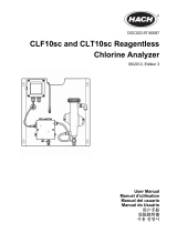
7.1 Nameplate
Fig. 1 Nameplate, Conex
®
DIA-2
TM04 0452 0708
Pos. Description
1 Type designation
2 Model
3 Product name
4 Voltage [V]
5 Frequency [Hz]
6 Product number
7 Country of origin
8 Year and week of production
9 Marks of approval, CE mark, etc.
10 Power consumption [VA]
11 Enclosure class
12 Serial number
DIA-2 1-D/HP 2-P, W-G
354-2200-10001
S/N: 08/08565
Conex DIA-2
230/240V 50/60Hz, 15 VA, IP 65
96622366P1108060808565
1
2
3
4
5
789
10
11
12
6

English (GB)
8
7.2 Type key, Conex
®
DIA-2 controllers
Type key example: DIA-2, 1-D/HP 2-P, W-G
Example: DIA -2 1-D/HP 2-P -W -G
Measuring amplifier and controller
DIA-2 Dosing Instrumentation Advanced with 2 inputs
Input parameter 1
D Chlorine (Cl
2
), chlorine dioxide (ClO
2
) or ozone (O
3
)
HP Hydrogen peroxide (H
2
O
2
)
Input parameter 2
PpH
Mounting
W Wall-mounted
P Panel-mounted
Voltage
G 1 x 230 V, 50/60 Hz
H 1 x 120 V, 50/60 Hz
I24 VDC

English (GB)
9
7.3 Type key, Conex
®
DIA-2 preassembled systems
Type key example: DIA-2-A, D1-P-PT-PCB-QS-T, W-G
Example: DIA -2 -A D1 -P -PT -PCB -QS -T W -G
Units for measurement and control
DIA-2 Dosing Instrumentation Advanced, with 2 inputs
Assembly
A Preassembled
Cell type
D1 Pressure-proof, with cleaning motor
D11 Pressure-proof, with cleaning motor
D2 Pressure-proof, with hydro-mechanical cleaning
D12 Pressure-proof, with hydro-mechanical cleaning
D3 Pressureless, with hydro-mechanical cleaning
D13 Pressureless, with hydro-mechanical cleaning
D4 For total chlorine measurement
D5 For free chlorine measurement with buffer dosing
P/R pH or redox (ORP) only
P With pressure retention valve
X Without pressure retention valve
Disinfection electrodes
AU Gold
PT Platinum
X No disinfection measuring
Other electrodes
PCB pH, ceramic diaphragm, incl. buffer solution
PTB pH, PTFE diaphragm, incl. buffer solution
PKB pH, KCl filling, incl. buffer solution
PGB pH, gel filling incl. buffer solution
PCX pH, ceramic diaphragm, excl. buffer solution
PTX pH, PTFE diaphragm, excl. buffer solution
PKX pH, KCL filling, excl. buffer solution
PGX pH, gel filling, excl. buffer solution
X No electrode
Flow sensor
QS Flow sensor integrated
X No flow sensor
Temperature sensor
T With Pt100
X No temperature sensor
Mounting
W Wall-mounted
P Panel-mounted
Voltage
G 1 x 230 V, 50/60 Hz
H 1 x 120 V, 50/60 Hz
I24 VDC

English (GB)
10
8. Technical data
8.1 Design / enclosure class
8.2 General data
8.3 Electronic data and functions
8.3.1 Electronics
8.3.2 Functions of the instrument amplifier
Wall-mounted
enclosure
(distance from
sensors up to three
metres)
IP65
Control panel
enclosure
including separate
potentiostat
IP54 (front) /
IP65 (sensor interface)
(distance from sensor
interface up to 100 metres,
distance from sensor
interface to sensors up to
three metres)
Input power Approximately 15 VA
Permissible
ambient
temperature
0 °C to +45 °C
Permissible
storage
temperature
-20 °C to +65 °C
Maximum relative
humidity
90 % (non-condensing)
Weight 1.5 kg
Enclosure
Plastic (control panel
enclosure: noryl,
wall-mounted
enclosure: ABS)
Power supply
versions
• 230/240 V (50/60 Hz)
(standard model)
• 115/120 V (50/60 Hz)
• 24 VDC
Electronics 16-bit microprocessor
Display
High-resolution graphics LCD
with background light
Potential-free relay
outputs
1 alarm relay, 2 controller
relays (250 V / 6 A, maximum
550 VA)
Signal inputs Controller stop; water sensor
Signal outputs
4 analog outputs 0/4 to 20 mA,
freely adjustable, maximum
load 500 Ω
Freely adjustable
analog outputs for
measured values
• Parameter group 1:
chlorine, chlorine dioxide,
ozone or peroxide
• Parameter group 2: pH
• For temperature or
continuous control (0/4 to
20 mA) of the parameters
from group 2 (pH)
• For continuous control (0/4
to 20 mA) of the
parameters from group 1
(chlorine, chlorine dioxide,
ozone or peroxide)
Display mode
Measured-value display:
measured value with its unit,
temperature display:
in °C or °F
Temperature
compensation
Manual or automatic with
Pt100
Calibration
Manual, or with automatic
recognition of buffer solution

English (GB)
11
8.3.3 Setpoint controller functions
8.4 Measuring ranges
Controller output
Limit monitor, interpulse controller (P, PI, PID), pulse frequency controller (P,
PI, PID), continuous controller (P, PI, PID)
Limit
0 to 100 % of measuring range, adjustable in the unit of the measured value
(only with limit monitor)
Hysteresis
0 to 50 % of full-scale value, adjustable in the unit of the measured value
(only with limit monitor)
Setpoint input 0 to 100 % of measuring range, adjustable in the unit of the measured value
Proportional band X
p
0.1 to 3000.0 %
Reset time T
n
1 to 3000 seconds, resolution 1 second (only with PI, PID controllers)
Derivative action time T
v
0 to 1000 seconds, resolution one second (only with PID controller)
Interpulse period 1 to 100 seconds (only with interpulse controller)
Minimum ON time T
min
0.1 to 10.0 seconds (only with interpulse controller)
Maximum frequency 1 to 180 pulses per minute (only with pulse frequency controller)
Basic load 0 to 50 % of dosing rate
Maximum dosing rate Value (basic load + 1) to 100 % of dosing rate
Control direction Adjustable to upward or downward control
Controller stop Adjustable to NC or NO
CI
2
CIO
2
O
3
H
2
O
2
pH Pt100
mg/l mg/l mg/l mg/l pH C°
0.00 - 0.50 0.00 - 0.50 0.00 - 0.50 0-100 0.00 - 14.00 -5 to +120
0.00 - 1.00 0.00 - 1.00 0.00 - 1.00 0-500 2.00 - 12.00
0.00 - 2.00 0.00 - 2.00 0.00 - 2.00 0-1000 5.00 - 9.00
0.00 - 5.00 0.00 - 5.00 0.00 - 5.00 0-2000
0.00 - 10.00 0.00 - 10.00
0.00 - 20.00
Note
The measuring ranges are also freely
adjustable (within the above-mentioned
range limits).

English (GB)
12
8.5 Dimensions
Fig. 2 Wall-mounted enclosure Conex
®
DIA-2
Fig. 3 Control panel enclosure Conex
®
DIA-2
TM03 6687 4506
59
125
84
59.5
184.5
212
198
10
145
27
110
180
Ø 4.5
TM03 6688 4506
90
96
96
166
90
158
90
18

English (GB)
13
9. Installation
9.1 Transport and storage
• Transport the device carefully, do not drop!
• Store at dry and cool location.
9.2 Unpacking
1. Check the device for damage.
Install as soon as possible after unpacking.
2. Do not install or connect damaged devices!
9.3 Installation requirements
• Dry room
• Room temperature: 0 °C to 45 °C
• Vibration-free location.
9.4 Installation in control panel
Fig. 4 Control panel enclosure Conex
®
DIA-2
Fig. 5 Sensor interface
1. Make an opening of 92 + 0.8 mm x 92 + 0.8 mm
in the control panel.
2. Slip on the supplied gasket.
3. Insert the Conex
®
DIA-2 into the opening from
the front.
1. Hook the clamps into the tightening cones on the
sides at the top and bottom.
2. Secure the device from the rear using a
screwdriver.
3. Install a separate sensor interface near the
sensors (maximum distance of three metres).
Note
Retainthe packing material or dispose of it
according to local regulations.
Caution
If you do not observe the installation
requirements, the device may be
damaged!
The measurements may not be correct!
TM03 6689 4506TM03 6690 4506
Caution
Do not damage the gasket!
The gasket must be fitted exactly!
92
+0.8
92
+0.8
> 20
> 20

English (GB)
14
9.5 Installation of wall-mounted enclosure
Fig. 6 Wall-mounted enclosure Conex
®
DIA-2
1. Drill three holes (∅8 mm) as shown in the
diagram, and insert the supplied dowels.
2. Screw the screw (A) into the top centre dowel
until it projects by approximately 1 cm. See fig. 7.
3. Loosen the fastening screws of the front panel,
and remove the front panel.
4. Hang the instrument onto the screw (A).
5. Tighten the instrument with the two screws (B).
6. Mount the front panel of the enclosure.
Fig. 7 Mounting drawing
Warning
Switch off the power supply before
installing!
Enclosure class IP65 is only guaranteed if
the terminal cover is correctly sealed, if the
front panel of the terminal enclosure is
closed and the appropriate cable glands or
dummy caps fitted.
Caution
Do not damage the terminal cover gasket!
The terminal cover gasket must fit exactly!
TM03 6691 4506
198
145
27
10.5
TM03 6692 4506
B
B
A

English (GB)
15
10. Commissioning / electrical
connections
1. Remove the terminal cover on the front of the
device.
2. Use the appropriate cable feedthroughs and
tighten the screws carefully.
3. Connect the cables used to the terminals
according to the Conex
®
DIA-2 terminal
assignment.
4. Close the terminal cover again with correctly
positioned gasket.
Warning
Switch off the power supply before
installing!
Enclosure class IP65 is only guaranteed with
the front panel of the terminals enclosure
closed and with appropriate cable glands or
dummy caps.
Warning
Switch off the power supply before
connecting the power supply cable and
relay contacts! For safety reasons, the
protective conductor must be connected
correctly!
Observe the local safety regulations!
Protect the cable connections and plugs
from corrosion and moisture.
Caution
Before connecting the power supply cable,
check that the supply voltage specified on
the nameplate corresponds to the local
conditions!
An incorrect supply voltage may destroy
the device!
To guarantee electromagnetic compatibility
(EMC), the input and current output cables
must be screened.
Connect the screening to the screen
ground on one side.
Refer to the wiring diagram! Route the
input, current output and power supply
cables in separate cable channels.
Caution
Enclosure class IP65 is only guaranteed if
the terminal cover is correctly sealed! Do
not damage the gasket on the terminal
cover!
The gasket on the terminal cover must be
positioned precisely!
Do not damage the gasket!
Note
Unused terminals must remain open.

English (GB)
16
10.1 Terminals
10.1.1 Wall-mounted enclosure Conex
®
DIA-2
Fig. 8 Terminals of wall-mounted enclosure
TM03 6977 4506
15
17 19 21 23 25
27
29 31 33 35
3634323028262422201816
15 17 19 21 23 25 27 29 31 33 35
3634323028
262422201816
37 38 39 40 41 42
37 =
38 = M
15 17
19
21 23 25 27 29 31 33 35
3634323028262422201816
H
2
O
2
15 (wh)
16 (br)
17 - 22
23 - 30
32,34,36
810
7
9
12
N.C.
N.O
.
11 13
12 14
21/22 = Pt 100
19 = + H
2
O, 20 = – H
2
O
17/18 =
1
2
3
4
Cl
2
,ClO
2
,O
3
,
H
2
O
2
T /
+
–
mA
pH
mA
mA
mA
mA
39 = B/R
40 = G/C
+
–
+
–
+
–
41/42 =
+/–
pH
1
4
1
4
P1
P2
P2
P1
1 3 5
2 4 6
L
1 3 5
2 4 6
+ -
+ -
115/120 V
230/240 V
24 V/DC
NPE
LNPE
Relays
Alarm
Cell
Sensors
Outputs
Cells / electrodes
Outputs
Sensors
(water)
Controller stop
24 V/DC
115/120 V
230/240 V
15 (white)
16 (brown)

English (GB)
17
10.1.2 Control panel enclosure Conex
®
DIA-2
Fig. 9 Terminals of control panel enclosure
TM03 6978 4506
2/1
2/2
2/3
2/4
2
/1, 2/2
=
5/1 - 5/5
2/3 (+), 2/4 (–)
=
H
2
O
+
–
M B/R G/C
Pt 100
3/1 - 3/4
pH
–
Cl
2
, ClO
2
,
O
3
,
pH
3/1
3/2
3/3
3/4
4/1
4/2
4/3
4/4
7/1
7/2
7/3
N.C.
N.O.
1/1 (br), 1/2 (wh)
H
2
O
2
6/1
6/2
6/3
6/4
1
2
A 1/1 (br)
B 1/2 (wh)
H
2
O
2
A 2
/3 (+)
B 2 /4 (-)
H
2
O
1/11 1/13 4/1
1/12 1/14
4/3
4/2 4/4
3/1 3/3
3/2 3/4
B
A
1/11 -1/14
Pt 100
4/1 - 4/4
Conex DIA-2
5/1
5/2
5/3
5/4
5/5
5/1
5/2
5/3
5/4
5/5
1
2
3
4
T
Cl
2
, ClO
2
,
O
3
,H
2
O
2
,
pH
mA
5/1 - 5/5
4
1
1/1
1/2
1/3
1/4
1/5
1/6
1/7
1/8
1/9
1/10
1/11
1/12
1/13
1/14
8/1
8/2
8/3
PE
N
L
8/1
8/2
8/3
-
+
115/120 V
230/240 V
24 V/DC
H
2
O
2
Controller stop
(water)
Relays
Alarm
Cells:
Connection to
Conex
®
DIA-2
Cells
(water)
Outputs
Sensor interface
Cells / electrodes
Cells
Electrodes
Jumper
DIP
off on
24 V/DC
115/120 V
230/240 V
1/11 (brown), 1/2 (white)
1/1 (brown)
1/1 (white)

English (GB)
18
Legend of terminals
Control panel enclosure Conex
®
DIA-2
• Conex
®
DIA-2: for installation in the control panel.
• Sensor interface: for installation near the sensors.
10.2 Power supply connection
1. Control panel enclosure: Plug the plug strip into
the corresponding terminal strip at the rear side
of the device. Ensure correct orientation.
2. Connect the protective earth conductor (PE) to
terminal 5 (wall-mounted enclosure) or terminal
8/1 (control panel enclosure).
3. Connect the neutral conductor (N) (or the -
conductor with 24 V version) to terminal 3
(wall-mounted enclosure) or terminal 8/2 (control
panel enclosure).
4. Connect phase (L1) (or the + conductor with 24 V
version) to terminal 1 (wall-mounted enclosure)
or 8/3 (control panel enclosure).
Switch the device on and off by switching the power
supply on and off accordingly. The device itself is not
equipped with a separate on/off switch.
10.3 Relay outputs
With inductive loads (also relays and contactors),
interference suppression is necessary. If this is not
possible, protect the relay contacts using a suppressor
circuit as described below.
• With AC voltage:
• With DC voltage: Connect the free-wheeling
diode in parallel to relay or contactor.
Fig. 10 Suppressor circuit, DC/AC
Pos. Description
Relays Relay 1 + 2
Alarm
Alarm relay
– N.O.: normally open
– N.C.: normally closed
Pt100 Temperature sensor
H
2
O Water sensor
Stop
Controller stop
(NO or NC selectable)
Outputs Current outputs [mA]
1
Cl
2
(chlorine),
ClO
2
(chlorine dioxide),
O
3
(ozone) or
H
2
O
2
(hydrogen peroxide)
2pH
3
T/P2: temperature / continuous
controller parameter 2
4
P1: output of continuous controller
parameter 1
Electrodes
Measuring cells, electrodes and
single-rod measuring chains
M Measuring electrode
B/R Reference electrode
G/C Counter electrode
Earth
mV pH electrode
Screen
Note
The connection of the relay outputs
depends on the application and the final
control elements used. Therefore the
connections described below should only
be considered as guidelines.
Current up to Capacitor C Resistor R
60 mA 10 nF, 275 V 390 Ω, 2 W
70 mA 47 nF, 275 V 22 Ω, 2 W
150 mA 100 nF, 275 V 47 Ω, 2 W
1.0 A 220 nF, 275 V 47 Ω, 2 W
Caution
Provide the relay outputs with a
corresponding backup fuse!
TM03 7209 2813
+
-
DC
R
C
AC

English (GB)
19
10.4 Current output
The current output can be set to one of the two
standard ranges "0-20 mA" or "4-20 mA", or it can be
freely adjusted.
• Connect the screen to earth (PE) at one end.
Output 1: chlorine, chlorine dioxide, ozone,
hydrogen peroxide (parameter 1)
This current output shows the displayed measured
value as an analog current signal.
Use of current signal for measured values:
• as input signal for another indicator
• as input signal for an external controller.
1. Connect the + conductor to terminal 23
(wall-mounted enclosure) or terminal 1/3 (control
panel enclosure).
2. Connect the - conductor to terminal 24
(wall-mounted enclosure) or terminal 1/4 (control
panel enclosure).
Output 2: pH (parameter 2)
This current output shows the displayed measured
value as an analog current signal.
Use of current signal for measured values:
• as input signal for another indicator
• as input signal for an external controller.
1. Connect the + conductor to terminal 25
(wall-mounted enclosure) or terminal 1/5 (control
panel enclosure).
2. Connect the - conductor to terminal 26
(wall-mounted enclosure) or terminal 1/4 (control
panel enclosure).
Output 3: continuous controller parameter 2 (or
temperature)
Shows the calculated actuating variable signal of the
controller as an analog current signal.
Use of actuating variable signal:
• as input signal for a final control element with
current input
or temperature output:
Shows the temperature measured by the optional
temperature sensor as an analog current signal.
Use of temperature current signal:
• as input signal for another indicator.
1. Connect the + conductor to terminal 27
(wall-mounted enclosure) or terminal 1/6 (control
panel enclosure).
2. Connect the - conductor to terminal 28
(wall-mounted enclosure) or terminal 1/7 (control
panel enclosure).
Output 4: continuous control parameter 1
This current output shows the calculated actuating
variable signal as an analog current signal.
Use of actuating variable signal:
• as input signal for a continuous final control
element.
1. Connect the + conductor to terminal 29
(wall-mounted enclosure) or terminal 1/8 (control
panel enclosure).
2. Connect the - conductor to terminal 30
(wall-mounted enclosure) or terminal 1/7 (control
panel enclosure).
10.5 Connections of controller stop,
sample-water sensor and temperature
sensor
Connecting the controller stop
1. Connect the + conductor to terminal 17
(wall-mounted enclosure) or terminal 2/1 (control
panel enclosure).
2. Connect the - conductor to terminal 18
(wall-mounted enclosure) or terminal 2/2 (control
panel enclosure).
Connecting the sample-water sensor
Cable colours and marking: See connections of
measuring-cell types
AQC-D1/-D11/AQC-D2/-D12/AQC-D3/-D13.
1. Connect the + conductor to terminal 19
(wall-mounted enclosure) or terminal 2/3 (control
panel enclosure).
2. Connect the - conductor to terminal 20
(wall-mounted enclosure) or terminal 2/4 (control
panel enclosure).
Connecting the Pt100 temperature sensor
1. Connect the + conductor to terminal 21
(wall-mounted enclosure) or terminal 1/11
(control panel enclosure).
2. Connect the - conductor to terminal 22
(wall-mounted enclosure) or terminal 1/12
(control panel enclosure).
Caution
Make sure that the polarity of the current
output is correct!
Maximum load: 500 Ω.
Note
When using measuring cell AQC-D2/-D12,
the water sensor must always be
connected and activated!

English (GB)
20
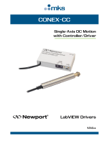
10.6 Connection of measuring cells
Jumper setting
• All cell types: position 1 (standard).
Fig. 11 Jumper setting
10.6.1 Connection of wall-mounted enclosure
Conex
®
DIA-2
Fig. 12 Connection to measuring cells
AQC-D1/AQC-D2/AQC-D3
Fig. 13 Connection to measuring cell
AQC-D11
Fig. 14 Connection to measuring cell
AQC-D12
Fig. 15 Connection to measuring cell
AQC-D13
Fig. 16 Connection to measuring cells HP
(peroxide)
TM03 6696 4506
TM03 5872 4112TM04 8642 4112
1
2
2
1:
Standard
7
5
1
37
38 39
40
41 42
6
12
4
1
15 17
19
21 23 25 27 29 31 33 35
3634323028262422201816
9, 10, 11
8
2
3
4
21
19
2220
4
12
11
1
1
38 40
39
9
8
10
TM04 8643 4112TM04 8644 4112TM03 6966 4112
7
10
9
1
6
2
37 38
39
40
8
21
19
2220
4
12
11
1
1
7
10
9
1
6
2
37 38
39
40
8
21
19
2220
2
12
11
COM
11
1
NC
12
15 17 19 21 23 25 27 29 31 33 35
3634323028262422201816
37 38 39 40 41 42
21
14 15
/