Page is loading ...

1
IMPORTANT:
Go to www.extron.com for the complete
user guide, installation instructions, and
specifications before connecting the
product to the power source.
XTP T UWP 202 4K • Setup Guide
The XTP T UWP 202 4K is a two-input XTP Decorator-Style Wallplate Transmitter that can be installed into the provided mud ring or a UL Listed
metal junction box. This guide provides instructions for an experienced installer to install and connect the XTP T UWP 202 4K.
Throughput and Control
Connections
Power Connection,
Reset Button, and
Input Connections
A
XTP output connector
B
RS-232 and IR Over
XTP connector
C
Remote RS-232
connector
D
LAN connector (LAN
model only)
E
USB configuration
connector
F
DC power connector
G
Reset button
H
HDMI input
connector
I
Analog audio input
connector
J
Female 15-pin HD
VGA connector
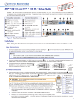
Figure 1. XTP T UWP 202 4K Rear (Left) and Front (Right) Panel Features (LAN Model)
Installation
NOTE: If using a junction box, use a metal box only.
• Ensure the installation meets building, electrical, and safety codes.
• For additional mounting considerations, see the XTP T UWP 202 4K
User Guide at www.extron.com. For metal junction boxes, refer to the
manufacturer for additional mounting instructions and considerations.
ATTENTION:
• Do not mount multiple devices adjacent to each other in the
same metal junction box. Add at least a one gang space
between devices.
• Ne procédez pas à une installation juxtaposée des appareils
dans le même boîtier de dérivation métallique. Veuillez laisser
un espace d’un gang minimum entre chaque appareil.
Installing a Junction Box or Mud Ring
Follow the steps below if mounting the XTP T UWP 202 4K in a junction box or
mud ring.
Installation site preparation
1. Use a soft pencil to mark guidelines on the mounting surface. For
accuracy, use a template or the mounting enclosure.
NOTE: Install junction boxes against wall studs.
2. Cut a hole in the wall. To avoid making the hole too big, cut inside the
marked lines.
3. If using the mud ring in a wall with insulation inside, remove at least six
inches of the insulation around the cutout. If a wall stud interferes with
removing the insulation, remove as much insulation as possible between
the cutout and the wall stud.
4. Test the t by inserting the mud ring or metal junction box into the hole in
the wall. If necessary, enlarge the hole as needed.
Metal junction box or mud ring installation
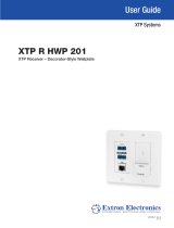
• To install a UL Listed metal junction box (see gure 2), use mounting
screws to fasten the box to a wall stud.
• To install the provided mud ring (see gure 3), attach the mounting
screws to the mud ring and loosely attach backing clips to the ends of
the screws. Rotate the backing clips so the mud ring ts in the opening
and then tighten them to t snugly against the back of the wall.
Tx
RS-232
XTP T UWP 202 4K
RS-232IR
Rx Tx RxGTxRxG
12V
1.0 A MAX.
POWER
OVER XTP
XTP OUT
REMOTE
PWR HDCP HDMI
HDMI IN
LAN
VGA
RESET
CONFIG
AUDIO
CLIP
AUTO
SWITCH
AUDIO IN
VGA IN
A
H
DE
IG
Rear
Front
J
BCF
XTP T UWP 202 4K
Signal Output
Cable
Cable
Clam
p
Decorator Faceplate
Screws or
Nails
Wall opening is
flush with edge
of box.
Wall Stud
PWR
HDCP
HDMI
HDMI IN
LAN
VGA
RESET
CONFIG
AUDIO
CLIP
AUTO
SWITCH
AUDIO IN
VGA IN
Figure 2. Metal Junction Box Installation
Backing Clip
Mounting Screw
Rotate the backing clip
out of the way to insert
the mud ring into the wall.
XTP T UWP 202 4K
Decorator Faceplate
PWR HDCP HDMI
HDMI IN
LAN
VGA
RESET
CONFIG
AUDIO
CLIP
AUTO
SWITCH
AUDIO IN
VGA IN
Figure 3. Mud Ring Installation

2
68-2729-50 Rev. A
04 19
Cabling and Mounting the XTP T UWP 202 4K
Rear Panel Connections
1. Connect a shielded twisted pair cable between the XTP connector (see figure 1,
A
on the previous page) of the XTP T UWP 202 4K and the XTP
input connector on an XTP twisted pair receiver or XTP matrix switcher.
ATTENTION: Do not connect this connector to a computer data or telecommunications network.
The XTP T UWP 202 4K is compatible with shielded twisted pair (F/UTP, SF/UTP, and S/FTP) cables.
Extron recommends using the following practices to achieve full transmission distances up to 330 feet
(100 meters) and reduce transmission errors.
• Use Extron XTP DTP 24 SF/UTP cable for the best performance. At a minimum, Extron recommends
24 AWG, solid conductor, STP cable with a minimum bandwidth of 400 MHz.
• Terminate cables with shielded connectors to the TIA/EIA-T568B standard (see table at right).
• Limit the use of more than two pass-through points, which may include patch points, punch down
connectors, couplers, and power injectors. If these pass-through points are required, use shielded
couplers and punch down connectors.
NOTE: When using shielded twisted pair cable in bundles or conduits, consider the following:
• Do not exceed 40% ll capacity in conduits.
• Do not comb the cable for the rst 20 meters, where cables are straightened, aligned, and
secured in tight bundles.
• Loosely place cables and limit the use of tie wraps or hook and loop fasteners.
• Separate twisted pair cables from AC power cables.
2. To pass bidirectional serial, infrared, or other control signals to a control or controllable device, connect
the device to the RS-232 and IR Over XTP connector (see figure 1,
B
). Wire the connector as shown to
the right.
NOTE: RS-232 and IR data can be transmitted simultaneously.
3. For serial RS-232 control of the XTP T UWP 202 4K, connect a host device or control system to the 3.5
mm, 3-pole captive screw connector (see figure 1,
C
). Wire the connector as shown to the right.
4. Power the XTP T UWP 202 4K in one of the following methods:
• Connect the provided external power supply to the 2-pole captive screw connector for local 12 V
power (see figure 1,
F
).
• Connect an XTP Power Injector to the XTP connection between the transmitter and a locally
powered XTP receiver or XTP matrix switcher.
• Connect the XTP T UWP 202 4K to an XTP matrix switcher and enable the remote power feature
on the XTP matrix switcher.
Mounting the XTP T UWP 202 4K to the metal junction box or mud ring
1. Using the provided screws, attach the XTP T UWP 202 4K to the mud ring or metal junction box through the inner screw holes (see figure 2 or 3).
2. Using the provided screws, attach the faceplate to the XTP T UWP 202 4K through the outer screw holes (see figure 2 or 3).
NOTE: For configuration, control, and firmware upgrades, connect a host device to the USB mini-B connector before attaching the
faceplate (see figure 1,
E
, and see the XTP T UWP 202 4K User Guide for details).
Front Panel Connections
1. Connect a digital video source to the female HDMI connector (see figure 1,
H
). The connector accepts HDMI, DVI (with an appropriate adapter),
or dual mode DisplayPort video signals.
2. Connect an unbalanced analog audio input source to the 3.5 mm TRS jack (see figure 1,
I
).
3. Connect an analog RGB video source to the female 15-pin HD VGA connector (see figure 1,
J
).
4. For LAN models, connect a host device or control LAN or WAN to the LAN RJ-45 connector for pass-through 10/100 Base-T Ethernet
communication (see figure 1,
D
). This is an Ethernet pass-through port with LEDs to indicate link and activity status.
Configuration and Control
After the transmitter and all connected devices are properly connected and powered on, the system is fully operational. To congure the transmitter,
connect a host device to the front panel USB conguration port (see figure 1,
E
). On the host device, use the Extron System Conguration Software
or SIS commands in DataViewer (see the XTP T UWP 202 4K User Guide at www.extron.com).
TIA/EIA-T568B
Pin Wire Color
1 White-orange
2 Orange
3 White-green
4 Blue
5 White-blue
6 Green
7 White-brown
8 Brown
12345678
RJ-45
Connector
Insert Twisted
Pair Wires
Pins:
Pin
1
2
3
4
5
6
7
8
Wire color
White-green
Green
White-orange
Blue
White-blue
Orange
White-brown
Brown
Wire color
T568A T568B
White-orange
Orange
White-green
Blue
White-blue
Green
White-brown
Brown
Tx/Rx
Pins
Tx
Rx
Rx Tx
IR Device
RS-232 Device
G
G
Tx Rx
G
OVER XTP
RS-232 IR
Tx
Rx
Rx TxGnd
RS-232 Device
Tx Rx
G
REMOTE
RS-232
© 2019 Extron Electronics — All rights reserved. www.extron.com
All trademarks mentioned are the property of their respective owners.
Worldwide Headquarters: Extron USA West, 1025 E. Ball Road, Anaheim, CA 92805, 800.633.9876
/