Page is loading ...

DIGITAL
PANEL
THERMOMETER
MODEL MI CRA-T
INSTRUCTION MANUAL
EDITION: April 2001
CODE: 30727001
MENU F1
-
INPUT CONFIGURATION
13
Pressing
ENTER
(from the previous step) allows access to the input type selection
menu.
Choose from one of three types of thermocouple inputs :
-1-
(thermocouple J),
-2-
(thermocouple K),
-3-
(thermocouple T) or P100 ( Pt100 input).
Press the
key to change the input type to the desired setting and press ENTER
to save the selection and advance to the next program step.
[13.2] Input type
TARE
MAX/MIN
DATA
ENTER
RS232C
RS485
MIN
TARE
PROG
SET 1
SET 2
MAX
F4
F2
F3
F1
The entry level of the input configuration module is represented by the fig. 13.1 (leds
F1 y PROG activated). Press
ENTER
to get access to this module.
Once completed the entire program sequence, the instrument returns to t
his stage.
To return to the run mode, press
and, when only the PROG LED is activated,
press
ENTER
to save changes in the memory and exit from the programming mode.
[13.1] Be
ginning
TARE
MAX/MIN
DATA
ENTER
RS232C
RS485
MIN
TARE
PROG
SET 1
SET 2
MAX
F4
F2
F3
F1
The current reading units appear on the display. Figure 14.2 shows one of the two
po
ssible options [
ºC
= Celsius,
ºF
= Fahrenheit]. To change this parameter, press the
key to switch to the desired units. Press
ENTER
to save the selection and
advance to the next program step.
[13.3] Unit
TARE
MAX/MIN
DATA
ENTER
RS232C
RS485
MIN
TARE
PROG
SET 1
SET 2
MAX
F4
F2
F3
F1

The indication shown in fig. 13.2 is viewed for 2 se
cons before the offset is allowed to
be programmed on next step.
Generally, it won t be necessary to program any amount of offset except in those
cases in wich a known difference may exist between the actual temperature and the
one the sensor reads. For ex
ample, if the sensor is located in a place where there is a
10 degree below the temperature under control, it should be desirable to introduce an
offset of +10º.
After 2 s or by pushing
ENTER
, the instrument goes to the offset program
ming stage.
[14.2] OFFSET function
TARE
MAX/MIN
DATA
ENTER
RS232C
RS485
MIN
TARE
PROG
SET 1
SET 2
MAX
F4
F2
F3
F1
Fig. 14.1 shows the previously selected resolution. To modify, press
key until
the display show the desired resolution [
0.1º
= or
1º
= resolution]. Then, press
ENTER
key to validate the choice and pass to the next step.
[14.1] Resolution
TARE
MAX/MIN
DATA
ENTER
RS232C
RS485
MIN
TARE
PROG
SET 1
SET 2
MAX
F4
F2
F3
F1
The previously programmed offset appears on the display with the first digit in flash.
To change the value, press
to increment the active digit value (the first digit
can only be '0' or a minus sign). Press
to shift to the next digit to be modified
and repeat these operations until desired offset is completed on
the display. The offset
is programmable from -9.9 to +9.9 with resolution of 0.1° and from -
99 to +99 whith
resolution of 1º.
Press
ENTER
to validate changes and exit from the input configuration.
The TARE"
[14.3] OFFSET value
TARE
MAX/MIN
DATA
ENTER
RS232C
RS485
MIN
TARE
PROG
SET 1
SET 2
MAX
F4
F2
F3
F1
14
2
INTRODUCTION TO THE
KOSMOS
MICRA
-
T SERIES
This m anual does not constitut e a form al agreem ent.
All inform ation given in this m anua l is subject to
change without notice.
DITEL brings a new philosophy in digital panel
instr
umentation by using multipurpose, modular-
concept
devices providing a rich
array of basic functions and
advanced cap
a
bilities.
With a fully MODULAR DESIGN, it is possible to implement a
wide variety of applications simply by adding the desired
option(s).
Built
-
in intelligence allows the meter to recognize the options
in
stalled
and implement the necessary parameters to properly
function within desired parameters. The basic instrument
without output options omits these data in the program
ro
u
tines.
CALIBRATION is performed at the factory eliminating the
need for adjustment poten
tiometers. Any circuit or option
liable to be adjusted incorporates a memory where calibration
parameters are stored, making it possible the optional cards
be totally interchangeable without need of any subsequent
adjustments.
Custom CONFIGU
RATION for specific applications can be
made quickly and easily through three or five front panel
keys, following structured choice menus aided by display
prompts at each programming step.
Other features of the LCIx08 family include :
CONNECTIONS via pl
ug
-
in terminal blocks without
screws and CLEMP
-
WAGO clips cable retention system.
DIMENSIONS
Models ALPHA & BETA 96x48x120 mm DIN 43700
Models JUNIOR, JUNIOR20, & MICRA 96x48x60 mm DIN
43700
CASE MATERIAL UL
-
94 V0
-
rated poly
-
carbonate.
PANEL INSTALLA
TION by means of single part
fingertip without screws.
To guarantee the meter s technical specifications, its is advised
to check calibration parameters at periodical intervals according
to the ISO9001 standards for the particular application
operating criteria.
Recalibration of the meter should be made at the factory or in a
qualified laboratory.

DIGITAL PANEL METER
KOSMOS SERIES
MI CRA
-
T
3
INDEX
1 . MODEL MICRA
-
T OVERVIEW
........................................................................................................................................
4-5
1.1.
FRONT
-
PANEL DESCRIPTION
...................................................................................................................
6-7
2 . SETUP AND OPERATION
.................................................................................................................................................
8
2.1
POWER SUPPLY AND CONNECTORS
........................................................................................................
9-
10
2.2
PROGRAMMING INSTRUCTIONS
................................................................................................................
11
2.3
INPUT CONFIGU
RATION
..............................................................................................................
11
-
12
-
13
-
14
2.4
INPUT SIGNAL CONNECTION
.....................................................................................................................
15
2.5
PROGRAMMING LOCK
-
OUT
........................................................................................................................
16
3 . MEMORY FUNCTIONS
...................................................................................................................................................
17
4. OUTPUT OPTIONS
........................................................................................................................................................
18
5 . TECHNICAL SPECIFICATIONS
........................................................................................................................................
19
5.1
-
DIMENSIONS AND MOUNTING
...................................................................................................................
20
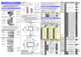
15
Wiring schematic for Pt100
with three wires
Wiring schematic for thermocouple J, K or T
with two wires
2.4.
Input signal connection
Refer to the transducer s specifications and to the
wiring advisements given
in page 10
.
SIGNAL CONNECTION (CN2)
PIN 1 =
-
TC (signal negative)
PIN 2 = +TC (signal positive
)
PIN 3 = Pt100
PIN 4 = Pt100
PIN 5 = Pt100 (Common)
5
4
3
2
1
5
4
3
2
1
THERMOCOUPLE

16
4
RS6 or MAN
OUTPUT OPTION
MAIN
BOARD
CASE WITH PANEL
FIXING CLIPS
FRONTAL COVER
2RE OUTPUT
OPTION
DISPLAY and
KEYBOARD MODULE
Remove jumper to lockout the
programming
Display board (solder side)
2.6
Programming lockout
After completing the instrument s programming, it is
recommended to lockout the access to the programming to
prevent from accidental or unauthorized modifications.
This operation is made by taking off a plug-
in jumper located
on the solder side of display board circuit (see figure at right).
NOTE :
Disconnect power before changing
the jumper position.
While the instrument is locked out it is however possible to
access to the programming routines to check th
e current
configuration, but it won t be possible to entry or modify data.
In this case, a push of ENTER
to access the programming
routines will show the indication
dALA
instead of
Pro
.

6 7
5
1. MODEL MICRA
-
T
The MICRA-T model is a four-
digit, small format instrument
that accep
ts virtually any voltage or current process signal
to measure process variables with direct indication in
engineering units.
Designed as simple, low-
cost indicators but keeping the
high performance qualities of the MICRA series, the MICRA
models are well
suited for applications of indication only
with the possibility of incorporating communication outputs
or analog output and setpoint control.
Fully software programmable, the MICRA-
T model provides
selectable input type sensor Pt100 or Thermocouple J,K,T.
Software configuration allows selection of reading units
(Celsius or Fahrenheit), resolution (degrees or tenths of
degree) and offset (
-
99 to 99 points).
Other standard featu
res of the indicator are memory
storage and display of the maximum (peak) and minimum
(valley) readings as well as tare operation and reset of
these memories.
The basic instrument is a soldered assembly composed of
the main board, the display and keyboard
module and the
input card.
Extended capabilities are furnished by an optional output
card that incorporates the RS232C and RS485 (RS6)
communication protocols or analogue 4-
20 mA output card
(MAN) and a control card with 2 SPDT 8A relays (2RE).
Eac
h option provides independent connectors protruding
out of the rear of the m eter, status LED's visible from the
front and a specific programm ing m odule which is
automatically activated once the card is installed.
The outputs are opto-isolated with respect
to the input
signal, to the relay outputs and the power supply.
This instrument conforms the following community standards: 89/336/CEE and 73/23/CEE
WARNING: Refer to the instructions manual to preserve safety protections.
17
MIC
RA
-
T provides three keys, all of them are operative in the programming mode while only
TARE
and
MAX/MIN
can be used in
the run mode. It also provides four LEDs for control functions , two for output status indica
tion and two more for serial
option.
3. MEMORY FUNCTIONS
MAX/MIN
.
The instrument detects and memorizes the ma
ximum and minimum
values (peak and valley) reached by the variable after the last
reset.
The peak and valley values can be displayed at any moment during
normal operation by pressing
MAX/MIN
.
The first stroke recalls the peak value and
illuminates the MAX
led. The second stroke recalls the valley value and activates the
MIN led. The third stroke deactivates the led and returns the
meter to the normal reading.
To erase the peak and valley memories, press
MAX/MIN
to display
the value wanted to be eliminated ( MAX and MIN leds indicate
which one is present on display). Press again MAX/MIN
and hold it for
5s after which the display shows
999 or 9999 indicating that the
peak or valley memory
respectively has been reset back to these
values.
[22.1] Offset in the memory
TARE
MAX/MIN
DATA
ENTER
RS232C
RS485
MIN
TARE
PROG
SET 1
SET 2
MAX
F4
F2
F3
F1
TARE
M AX/M IN
DATA
ENTER
RS232C
RS485
MIN
TARE
PROG
SET 1
SET 2
MAX
F4
F2
F3
F1
[22.2] Reset of MIN value.
OFFSET.
Normally it s not necessary to program an
offset but it should be useful to com pensate differences
due to the sensor position or other reason.

TARE
MAX/MIN
DATA
ENTER
RS232C
RS485
MIN
TARE
PROG
SET 1
SET 2
MAX
F4
F2
F3
F1
FRONT
-
PANEL FUNCTIONS DESCRIPTION (RUN MODE)
9
6
LED MAX / F1
Indicates peak displayed
LED MIN / F3
Indicates valley displayed
TARE KEY
No function in run mode
DISPLAY
Displays the variable being measured
LED RS485
RS485 selected
KEYBOARD IN RUN MODE
LABEL
Engineering units
KEY DATA
Shows
programming data
Gives access to PROG mode.
MAX/MIN KEY
first push:
Recalls Peak
second push:
Recalls Valley
push 5s :
RESET of Peak or Valley
LED RS32C
RS232C selected
LED TARE / F2
Indicates offset activated
LED PROG / F4
not used in RUN mode
As an option, the LCI-
208
-
1x model can incorporate one or two of
the following output cards ( The LCIA-10 and the LCIA-
06 options
are exclusive and can not be installed togethe
r in the same
instrument)
A serial outputs card with RS232C and RS485 communications
protocol, 1200 to 9600 baud half-
duplex. Both types are included in
the option but only one of them can be operative as selected via
software.
THI S OUTPUT SHOULD NEVER B
E CONNECTED TO
THE TELEPHONE LINES
.
Ref. RS6
An analog output card that drives out a 4-
20 mA signal
proportional to a user
-
defined display range
. Ref. MAN
A control card with 2 SPDT 8
A @ 250 V AC / 150 V DC. The
outputs provide selectable HI/LO mode and programmable
hysteresis or time delay.
Ref. 2RE
The output options consist of additional cards that are supplied with
their specific instructi
ons manual describing characteristics,
installation, programming and operation.
Once installed in the meter s assembly by means of plug-
in
connectors, a program module is automatically included in the
software routines.
For more detailed information on c
haracteristics, applications,
mounting and programming, please refer to the specific manual
furnished with the option.
4. OUTPUT OPTIONS
18
2RE
2 RELAY
OUTPUT OPTION
SERIAL OUTPUT
OPTION
RS6
or
ANALOG OUTPUT
OPTION MAN

TARE
MAX/MIN
DATA
ENTER
RS232C
RS485
MIN
TARE
PROG
SET 1
SET 2
MAX
F4
F2
F3
F1
FRONT
-
PANEL FUNCTIONS DESCRIPTION (PROG MODE)
FUSES (DIN 41661)
MICRA
-
T(230/115V AC)
............................
F 0.1A / 250 V
MICRA
-
T2 (24/48V AC)
.............................
F 0.2A / 250 V
MICRA
-
T3 (12 V DC)
...................................
F 1A / 250 V
MICRA
-
T4 (24 V DC)
................................
F 0.5A / 250 V
MICRA
-
T5 (48 V DC)
................................
F 0.5A / 250 V
A/D CONVERSION
Technique
.......................................................
dual slope
Resolution
.............................................
(± 2000 counts)
Rate
......................................................................
12/ s
DISPLAY
Type
..............................
-
999/ 9999, 4 red 14 mm digits
Decimal point
...........................................
programmable
LEDs
........................
4 for control and 4 for output status
Update time
........................................................
330 ms
Over
-
range or sensor
-
break indication
.......................
OvE
EN
VIRONMENTAL
Indoor Use
Operating temperature
............................
0 ºC to +50 ºC
Storage temperature
............................
-
25 ºC to +85 ºC
Relative humidity (non condensing)
.........
<95 % at 40 ºC
Max Altitude
...............................................
2000 meters
DIMENSIONS
Dimensions
...............................................
96x48x60 mm
Panel cutout
..................................................
92x45 mm
Weight
................................................................
.
250 g
Case material
.........................
polycarbonate s/UL 94 V
-0
5.
TECHNICAL SPECIFICAT
IONS
19
INPUT SIGNAL
Configuration
.............................
differential asymmetrical
Cold junction compesation
.........................
-
10ºC to 60ºC
Excitation current for Pt100
................................
< 1 mA
Max. lea
d resistance
......................
40
/ wire (balanced)
Input
Range (res. 0.1 º)
Range (res. 1º)
-
50.0 a +200.0 ºC
-
50 a +800 ºC
TC J
-
58.0 a +392.0 ºF
-
58 a +1562 ºF
-
50.0 a +200.0 ºC
-
50 a +1250 ºC
TC K
-
58.0 a +392.0 ºF
-
58 a +2282 ºF
-
100.0 a +100.0 º C
-
200
a +400 ºC
TC T
-
100.0 a +212.0 ºF
-
328 a +752 ºF
-
100.0 a +200.0 ºC
-
100 a +800 ºC
Pt100
-
100.0 a +212.0 ºF
-
148 a +1472 ºF
ACCURACY A 23º ± 5º C
Error max.:
Pt100 (res. 0.1 ºC)
....
± (0.1% of the reading +0.2 ºC)
Pt100 (res. 1 ºC)
.......
± (0.1% of the reading +0.
6 ºC)
TC (res. 0.1 ºC)
........
± (0.2% of the reading +0.5 ºC)
TC (res. 1 ºC)
..............
± (0.2% of the reading +1 ºC)
Cold junction
............................
±(0.05 ºC/ ºC +0.25 ºC)
Temperature coefficient
..............................
100 ppm/ ºC
Warmup time
..................................................
5 minutes
POWER SUPPLY
AC
.....................
230/115 V, 24/48 V ±10% 50/60 Hz AC
DC
..
12V
(10.5 to 16V), 24V (21 to 32V), 48V (42 to 64V)
Consumption
...........................................................
3 W
7
KEY
Increases the value of flashing
digit
DISPLAY
Shows programming parameters
LED RS485
RS485 selected
LABEL
Engineering units
ENTER KEY
Accepts parameters and values
.
Goes to next programming step.
End programming.
KEY
Shift right
LED F2 / TARE
Module F2: output configuration:
Serial or analog
LED F4 / PROG
Programming mode
KEYBOARD
in PROGRAMMING MODE
LED SET1
programming setpoint
1
LED F1 / MAX
Module F1: Input configuration
LED F3 / MIN
Module F3: Display configuration
LED RS32C
RS232C selected
LED SET2
programming setpoint 2

Programming instructions
(page. 11)
The software inside the instrument allows configuring the
input parameters. If a 2RE, MAN or a RS6 option is
installed, the software detects it on power up enabling a
specific routine for its configuration.
Re
ad carefully this paragraph
.
Input type (
page 13
-
15
)
The instrument provides inputs for Pt100 or
Thermocouple J,K or T.
Check transducer type.
Programming lockout (
page 16)
As shipped from the factory, the instrument allows full
access to change pro
gramming parameters.
To disable the possibility of making changes on the
configuration, it is necessary to remove a plug-
in jumper
located on the solder side of the display board.
Check jumper position.
8
2. OPERATING INSTRUC
T
IONS
PACKING CONTENTS
Instructions manual
in English.
The digital panel instrument MICRA
-
T.
Accessories for panel mounting (sealing gasket and fixing
clips).
Accessories for wiring connection (removable terminal
block connectors and fingertip).
Wiring label affixed to the instrument s case. Set of
labels
with different engineering units.
Check packing contents.
CONFIGURATION
Power supply (pages 9 & 10)
The instruments for 115/230V AC power supply, are set up
at the factory for 230V AC.
(USA market 115 V AC)
.
The instruments for 24/48V AC power
supply, are set up
at the factory for 24V AC.
If the instrument is supplied for 12V DC, 24V DC or 48V
DC power supply, it is not necessary to make any change.
Check wiring label before connecting the
instrument to the mains supply.
PINZAS DE SUJECIÓN
20
5.1
-
Dimensions and mounting
To install the instrument into the panel,
make a 92x45mm cutout and insert the
instrument from the front placing the
sealing gasket between this and the
front bezel.
Place the fixing clips on both sides of
the case and slide them over the guide
tracks until they touch the panel at the
rear side.
Press slightly to fasten the bezel to the
panel and secure the clips.
To remove the instrument from the
panel, pull
outwards the fixing clips
rear tabs to disengage and slide them
back over the case.
CLEANING: The front cover should
be cleaned only with a soft cloth
soaked in neutral soap product.
DO NOT USE SOLVENTS
SEALING
GASKET
FIXING CLIPS
PANEL
CLIPS
RETENTION

Fig. 9.3.
Selector de alimentación de 115 V ó 24 V AC
9
2.1
Power supply and connectors
To change the meter s physical configuration remove the case as
shown in fig
ure 9.1.
115/ 230 V AC:
The instruments with 115/230 V AC power are
set up at fabrication for 230 V AC (USA market 115 V AC
), see
figure 9.2. To change power supply configuration to 115 V AC,
make the jumpers indicated in figure 9.3 and table 1. The wiring
label should be modified to match the new configuration.
24/ 48 V AC:
The instruments with 24/48 V AC power are set up
at fabrication for 24 V AC, see figure 9.2. To change power supply
configuration to 48 V AC, make the jumpers indicated in figure 9.3
an
d table 1. The wiring label should be modified to match the
new configuration.
12, 24 or 48V DC:
Instruments for DC
power are se
t up for
the supply voltage
specified in the wiring
label (12V, 24V or
48V according to the
order reference).
Fig. 9.1. Disassembly.
Fig. 9.2.
Jumper settings for 230 V or 48 V AC
Fig. 9.3.
Jumper settings for 115 V or 24 V
AC
Table 1. Jumper settings.
Pin
1 2 3 4 5
230V AC
-
115V AC
-
48V AC
-
24V AC
-

10
CONNECTORS
To perform wiring connections, remove the
terminal block from the meter s connector, strip
the wire leaving from 7 to 10mm exposed and
insert it into the proper terminal while pushing
the fingertip down to ope
n the clip inside the
connector as shown in the figure.
Proceed in the same manner with all pins and plug the terminal block
back to the corresponding meter s connector.
Each terminal can admit wires of section between 0.08 mm² and 2.5
mm² (AWG 26 ÷ 14).
S
ome terminals have removable adaptors to provide proper fastening for
wires of sections less than 0.5 mm².
POWER CONNECTION
AC VERSIONS
PIN 1
AC PHASE
PIN 2
GND (GROUND)
PIN 3
AC NEUTRAL
DC VERSIONS
PIN 1
DC POSITIVE
PIN 2
Not connected
PIN 3
DC NEGATIVE
INSTALLATION
To meet the requirements of the directive EN61010-
1, where the unit
is permanently connected to the mains supply it is obligatory to install
a circuit breaking device easy reachable to the operator
and clearly
marked as the disconnect device.
WARNING
In order to guarantee the electromagnetic compatibility, the following
guidelines should be kept in mind :
-
Power supply wires may be routed separated from signal wires.
Never run power and signal wires
in the same conduit.
-
Use shielded cable for signal wiring and connect the shield to the
ground of the indicator (pin2 CN1).
-
The cables section should be
0.25 mm
2
I f not installed and used in accordance with these
instructions, protection against hazards
may be impaired.
27
All products are warranted against defective material and workmanship for a
period of thre
e years from date of delivery.
If a product appears to have a defect or fails during the normal use within the
warranty period, please contact the distributor from whom you purchased the
product.
This warranty does not apply to defects resultin
g from action of the buyer
such as mishandling or improper interfacing.
The liability under this warranty shall extend only to the repair of the
instrument ; no responsibility is assumed by the manufacturer for any damage
which may result from its us
e.
.
6.
WARRANTY

TARE
MAX/MIN
DATA
ENTER
RS232C
RS485
MIN
TARE
PROG
SET 1
SET 2
MAX
F4
F2
F3
F1
11
2.2
Programming instructions
To en
ter in the programming mode
Connect the meter to the main supply, for approx. 1s a self-
test routine automatically activates all the digits of the display. After,
the instrument goes to the normal operating mode (RUN).
To enter in the programming mode pres
s
ENTER . On the display will appear
Pro
and F4 led activated. This led remains on as
long as we are in programming mode.
To exit from the programming mode
To return to the run mode, it is necessary to pass through the different menus with
, until the led F4/ PROG is the only
activated led . Then push
ENTER
. After, it automatically goes to the normal operating mode.
How to interpret the programming instructions
The programming
software routine is composed by a series of hierarchically organized menus, each allowing the setting of a
specific parameter. In general, the normal sequence at each step is to push the
key a number of times to make changes
and the
ENTER
key to store them i
nto the memory and advance to the next step.
The elements used along the programming instructions are described following.
The programming instructions for each menu step are accompanied by a figure
representing the display indication for the corresponding parameter. Pay special
attention to the LED indications and active
keys and follow the procedure described on
the text to introduce correctly the desired data.
When the display indication is represented with blank segments, it means that this is
one of the possible options of this menu (normally the default one) dependin
g on the
previous selection.
A series of blanked 8 represents any numerical value that can be changed by use of
keys
and
(change digit) and
(change value).
[11.1
] Programming mode

DECLARATION OF CONFO
RMITY
12
TO THE MAN
or RS6
OUTPUT
CONFIGURATION
MODULE (F2)
TO THE
SETP
OINTS
2RE
CONFIGURATION
MODULE
2.3
Input configuration.
The figure shows the diagram of the MICRA-T programming rout
ine where the MODULE 1 of input configuration has been
developed. The parametres to be configured are:
Sensor type , temperature units, resolution and if necessary offset.
To access to the selection of the input parameters, press ENTER to move on from the run to the programming mode (
Pro
indication,
PROG
LED activated) and
to get input menu.
Manufacturer :
DITEL
-
Diseños y Tecnología S.A.
Address :
Travessera de les Corts, 180
08028 Barcelona
ESPAÑA
Declares, that the product:
Name : Indicador Digital
Model :
MICRA
-T
Conforms with :
EMC 89/336/CEE
LVD 73/23/
CEE
Applicable Standards:
EN50081
-
1
Generic emission
EN55022/CISPR22
Clase B
Applicable Standards:
EN50082
-1
Generic immunity
IEC1000
-4-2
Level 3
Criteria B
Air Disc
harge 8kV
Contact Discharge 6kV
IEC1000
-4-3
Level 2
Criteria A
3V/m 80..1000MHz
IEC1000
-4-4
Level 2
Criteria B
1kV Power Lines
0.5kV Signal lines
Applicable Standards:
EN61010
-1
Generic Safety
IEC1010
-1
Installation Category II
Transient Voltages <2.5kV
Pollution degree 2
Conductive pollution excluded
Insulation Type
Enclosure :
Double
Inputs/Outputs: Basic
Date
:
25 March 1999
Sign
: José M. Edo
Position:
Technical Manager

DIGITAL
PANEL
THERMOMETER
MODEL MI CRA-T
INSTRUCTION MANUAL
EDITION: April 2001
CODE: 30727001
MENU F1
-
INPUT CONFIGURATION
13
Pressing
ENTER
(from the previous step) allows access to the input type selection
menu.
Choose from one of three types of thermocouple inputs :
-1-
(thermocouple J),
-2-
(thermocouple K),
-3-
(thermocouple T) or P100 ( Pt100 input).
Press the
key to change the input type to the desired setting and press ENTER
to save the selection and advance to the next program step.
[13.2] Input type
TARE
MAX/MIN
DATA
ENTER
RS232C
RS485
MIN
TARE
PROG
SET 1
SET 2
MAX
F4
F2
F3
F1
The entry level of the input configuration module is represented by the fig. 13.1 (leds
F1 y PROG activated). Press
ENTER
to get access to this module.
Once completed the entire program sequence, the instrument returns to t
his stage.
To return to the run mode, press
and, when only the PROG LED is activated,
press
ENTER
to save changes in the memory and exit from the programming mode.
[13.1] Be
ginning
TARE
MAX/MIN
DATA
ENTER
RS232C
RS485
MIN
TARE
PROG
SET 1
SET 2
MAX
F4
F2
F3
F1
The current reading units appear on the display. Figure 14.2 shows one of the two
po
ssible options [
ºC
= Celsius,
ºF
= Fahrenheit]. To change this parameter, press the
key to switch to the desired units. Press
ENTER
to save the selection and
advance to the next program step.
[13.3] Unit
TARE
MAX/MIN
DATA
ENTER
RS232C
RS485
MIN
TARE
PROG
SET 1
SET 2
MAX
F4
F2
F3
F1

The indication shown in fig. 13.2 is viewed for 2 se
cons before the offset is allowed to
be programmed on next step.
Generally, it won t be necessary to program any amount of offset except in those
cases in wich a known difference may exist between the actual temperature and the
one the sensor reads. For ex
ample, if the sensor is located in a place where there is a
10 degree below the temperature under control, it should be desirable to introduce an
offset of +10º.
After 2 s or by pushing
ENTER
, the instrument goes to the offset program
ming stage.
[14.2] OFFSET function
TARE
MAX/MIN
DATA
ENTER
RS232C
RS485
MIN
TARE
PROG
SET 1
SET 2
MAX
F4
F2
F3
F1
Fig. 14.1 shows the previously selected resolution. To modify, press
key until
the display show the desired resolution [
0.1º
= or
1º
= resolution]. Then, press
ENTER
key to validate the choice and pass to the next step.
[14.1] Resolution
TARE
MAX/MIN
DATA
ENTER
RS232C
RS485
MIN
TARE
PROG
SET 1
SET 2
MAX
F4
F2
F3
F1
The previously programmed offset appears on the display with the first digit in flash.
To change the value, press
to increment the active digit value (the first digit
can only be '0' or a minus sign). Press
to shift to the next digit to be modified
and repeat these operations until desired offset is completed on
the display. The offset
is programmable from -9.9 to +9.9 with resolution of 0.1° and from -
99 to +99 whith
resolution of 1º.
Press
ENTER
to validate changes and exit from the input configuration.
The TARE"
[14.3] OFFSET value
TARE
MAX/MIN
DATA
ENTER
RS232C
RS485
MIN
TARE
PROG
SET 1
SET 2
MAX
F4
F2
F3
F1
14
2
INTRODUCTION TO THE
KOSMOS
MICRA
-
T SERIES
This m anual does not constitut e a form al agreem ent.
All inform ation given in this m anua l is subject to
change without notice.
DITEL brings a new philosophy in digital panel
instr
umentation by using multipurpose, modular-
concept
devices providing a rich
array of basic functions and
advanced cap
a
bilities.
With a fully MODULAR DESIGN, it is possible to implement a
wide variety of applications simply by adding the desired
option(s).
Built
-
in intelligence allows the meter to recognize the options
in
stalled
and implement the necessary parameters to properly
function within desired parameters. The basic instrument
without output options omits these data in the program
ro
u
tines.
CALIBRATION is performed at the factory eliminating the
need for adjustment poten
tiometers. Any circuit or option
liable to be adjusted incorporates a memory where calibration
parameters are stored, making it possible the optional cards
be totally interchangeable without need of any subsequent
adjustments.
Custom CONFIGU
RATION for specific applications can be
made quickly and easily through three or five front panel
keys, following structured choice menus aided by display
prompts at each programming step.
Other features of the LCIx08 family include :
CONNECTIONS via pl
ug
-
in terminal blocks without
screws and CLEMP
-
WAGO clips cable retention system.
DIMENSIONS
Models ALPHA & BETA 96x48x120 mm DIN 43700
Models JUNIOR, JUNIOR20, & MICRA 96x48x60 mm DIN
43700
CASE MATERIAL UL
-
94 V0
-
rated poly
-
carbonate.
PANEL INSTALLA
TION by means of single part
fingertip without screws.
To guarantee the meter s technical specifications, its is advised
to check calibration parameters at periodical intervals according
to the ISO9001 standards for the particular application
operating criteria.
Recalibration of the meter should be made at the factory or in a
qualified laboratory.

DIGITAL PANEL METER
KOSMOS SERIES
MI CRA
-
T
3
INDEX
1 . MODEL MICRA
-
T OVERVIEW
........................................................................................................................................
4-5
1.1.
FRONT
-
PANEL DESCRIPTION
...................................................................................................................
6-7
2 . SETUP AND OPERATION
.................................................................................................................................................
8
2.1
POWER SUPPLY AND CONNECTORS
........................................................................................................
9-
10
2.2
PROGRAMMING INSTRUCTIONS
................................................................................................................
11
2.3
INPUT CONFIGU
RATION
..............................................................................................................
11
-
12
-
13
-
14
2.4
INPUT SIGNAL CONNECTION
.....................................................................................................................
15
2.5
PROGRAMMING LOCK
-
OUT
........................................................................................................................
16
3 . MEMORY FUNCTIONS
...................................................................................................................................................
17
4. OUTPUT OPTIONS
........................................................................................................................................................
18
5 . TECHNICAL SPECIFICATIONS
........................................................................................................................................
19
5.1
-
DIMENSIONS AND MOUNTING
...................................................................................................................
20
15
Wiring schematic for Pt100
with three wires
Wiring schematic for thermocouple J, K or T
with two wires
2.4.
Input signal connection
Refer to the transducer s specifications and to the
wiring advisements given
in page 10
.
SIGNAL CONNECTION (CN2)
PIN 1 =
-
TC (signal negative)
PIN 2 = +TC (signal positive
)
PIN 3 = Pt100
PIN 4 = Pt100
PIN 5 = Pt100 (Common)
5
4
3
2
1
5
4
3
2
1
THERMOCOUPLE

16
4
RS6 or MAN
OUTPUT OPTION
MAIN
BOARD
CASE WITH PANEL
FIXING CLIPS
FRONTAL COVER
2RE OUTPUT
OPTION
DISPLAY and
KEYBOARD MODULE
Remove jumper to lockout the
programming
Display board (solder side)
2.6
Programming lockout
After completing the instrument s programming, it is
recommended to lockout the access to the programming to
prevent from accidental or unauthorized modifications.
This operation is made by taking off a plug-
in jumper located
on the solder side of display board circuit (see figure at right).
NOTE :
Disconnect power before changing
the jumper position.
While the instrument is locked out it is however possible to
access to the programming routines to check th
e current
configuration, but it won t be possible to entry or modify data.
In this case, a push of ENTER
to access the programming
routines will show the indication
dALA
instead of
Pro
.

6 7
5
1. MODEL MICRA
-
T
The MICRA-T model is a four-
digit, small format instrument
that accep
ts virtually any voltage or current process signal
to measure process variables with direct indication in
engineering units.
Designed as simple, low-
cost indicators but keeping the
high performance qualities of the MICRA series, the MICRA
models are well
suited for applications of indication only
with the possibility of incorporating communication outputs
or analog output and setpoint control.
Fully software programmable, the MICRA-
T model provides
selectable input type sensor Pt100 or Thermocouple J,K,T.
Software configuration allows selection of reading units
(Celsius or Fahrenheit), resolution (degrees or tenths of
degree) and offset (
-
99 to 99 points).
Other standard featu
res of the indicator are memory
storage and display of the maximum (peak) and minimum
(valley) readings as well as tare operation and reset of
these memories.
The basic instrument is a soldered assembly composed of
the main board, the display and keyboard
module and the
input card.
Extended capabilities are furnished by an optional output
card that incorporates the RS232C and RS485 (RS6)
communication protocols or analogue 4-
20 mA output card
(MAN) and a control card with 2 SPDT 8A relays (2RE).
Eac
h option provides independent connectors protruding
out of the rear of the m eter, status LED's visible from the
front and a specific programm ing m odule w hich is
automatically activated once the card is installed.
The outputs are opto-isolated with respect
to the input
signal, to the relay outputs and the power supply.
This instrument conforms the following community standards: 89/336/CEE and 73/23/CEE
WARNING: Refer to the instructions manual to preserve safety protections.
17
MIC
RA
-
T provides three keys, all of them are operative in the programming mode while only
TARE
and
MAX/MIN
can be used in
the run mode. It also provides four LEDs for control functions , two for output status indica
tion and two more for serial
option.
3. MEMORY FUNCTIONS
MAX/MIN
.
The instrument detects and memorizes the ma
ximum and minimum
values (peak and valley) reached by the variable after the last
reset.
The peak and valley values can be displayed at any moment during
normal operation by pressing
MAX/MIN
.
The first stroke recalls the peak value and
illuminates the MAX
led. The second stroke recalls the valley value and activates the
MIN led. The third stroke deactivates the led and returns the
meter to the normal reading.
To erase the peak and valley memories, press
MAX/MIN
to display
the value wanted to be eliminated ( MAX and MIN leds indicate
which one is present on display). Press again MAX/MIN
and hold it for
5s after which the display shows
999 or 9999 indicating that the
peak or valley memory
respectively has been reset back to these
values.
[22.1] Offset in the memory
TARE
MAX/MIN
DATA
ENTER
RS232C
RS485
MIN
TARE
PROG
SET 1
SET 2
MAX
F4
F2
F3
F1
TARE
M AX/M IN
DATA
ENTER
RS232C
RS485
MIN
TARE
PROG
SET 1
SET 2
MAX
F4
F2
F3
F1
[22.2] Reset of MIN value.
OFFSET.
Normally it s not necessary to program an
offset but it should be useful to com pensate differences
due to the sensor position or other reason.

TARE
MAX/MIN
DATA
ENTER
RS232C
RS485
MIN
TARE
PROG
SET 1
SET 2
MAX
F4
F2
F3
F1
FRONT
-
PANEL FUNCTIONS DESCRIPTION (RUN MODE)
9
6
LED MAX / F1
Indicates peak displayed
LED MIN / F3
Indicates valley displayed
TARE KEY
No function in run mode
DISPLAY
Displays the variable being measured
LED RS485
RS485 selected
KEYBOARD IN RUN MODE
LABEL
Engineering units
KEY DATA
Shows
programming data
Gives access to PROG mode.
MAX/MIN KEY
first push:
Recalls Peak
second push:
Recalls Valley
push 5s :
RESET of Peak or Valley
LED RS32C
RS232C selected
LED TARE / F2
Indicates offset activated
LED PROG / F4
not used in RUN mode
As an option, the LCI-
208
-
1x model can incorporate one or two of
the following output cards ( The LCIA-10 and the LCIA-
06 options
are exclusive and can not be installed togethe
r in the same
instrument)
A serial outputs card with RS232C and RS485 communications
protocol, 1200 to 9600 baud half-
duplex. Both types are included in
the option but only one of them can be operative as selected via
software.
THI S OUTPUT SHOULD NEVER B
E CONNECTED TO
THE TELEPHONE LINES
.
Ref. RS6
An analog output card that drives out a 4-
20 mA signal
proportional to a user
-
defined display range
. Ref. MAN
A control card with 2 SPDT 8
A @ 250 V AC / 150 V DC. The
outputs provide selectable HI/LO mode and programmable
hysteresis or time delay.
Ref. 2RE
The output options consist of additional cards that are supplied with
their specific instructi
ons manual describing characteristics,
installation, programming and operation.
Once installed in the meter s assembly by means of plug-
in
connectors, a program module is automatically included in the
software routines.
For more detailed information on c
haracteristics, applications,
mounting and programming, please refer to the specific manual
furnished with the option.
4. OUTPUT OPTIONS
18
2RE
2 RELAY
OUTPUT OPTION
SERIAL OUTPUT
OPTION
RS6
or
ANALOG OUTPUT
OPTION MAN

TARE
MAX/MIN
DATA
ENTER
RS232C
RS485
MIN
TARE
PROG
SET 1
SET 2
MAX
F4
F2
F3
F1
FRONT
-
PANEL FUNCTIONS DESCRIPTION (PROG MODE)
FUSES (DIN 41661)
MICRA
-
T(230/115V AC)
............................
F 0.1A / 250 V
MICRA
-
T2 (24/48V AC)
.............................
F 0.2A / 250 V
MICRA
-
T3 (12 V DC)
...................................
F 1A / 250 V
MICRA
-
T4 (24 V DC)
................................
F 0.5A / 250 V
MICRA
-
T5 (48 V DC)
................................
F 0.5A / 250 V
A/D CONVERSION
Technique
.......................................................
dual slope
Resolution
.............................................
(± 2000 counts)
Rate
......................................................................
12/ s
DISPLAY
Type
..............................
-
999/ 9999, 4 red 14 mm digits
Decimal point
...........................................
programmable
LEDs
........................
4 for control and 4 for output status
Update time
........................................................
330 ms
Over
-
range or sensor
-
break indication
.......................
OvE
EN
VIRONMENTAL
Indoor Use
Operating temperature
............................
0 ºC to +50 ºC
Storage temperature
............................
-
25 ºC to +85 ºC
Relative humidity (non condensing)
.........
<95 % at 40 ºC
Max Altitude
...............................................
2000 meters
DIMENSIONS
Dimensions
...............................................
96x48x60 mm
Panel cutout
..................................................
92x45 mm
Weight
................................................................
.
250 g
Case material
.........................
polycarbonate s/UL 94 V
-0
5.
TECHNICAL SPECIFICAT
IONS
19
INPUT SIGNAL
Configuration
.............................
differential asymmetrical
Cold junction compesation
.........................
-
10ºC to 60ºC
Excitation current for Pt100
................................
< 1 mA
Max. lea
d resistance
......................
40
/ wire (balanced)
Input
Range (res. 0.1 º)
Range (res. 1º)
-
50.0 a +200.0 ºC
-
50 a +800 ºC
TC J
-
58.0 a +392.0 ºF
-
58 a +1562 ºF
-
50.0 a +200.0 ºC
-
50 a +1250 ºC
TC K
-
58.0 a +392.0 ºF
-
58 a +2282 ºF
-
100.0 a +100.0 º C
-
200
a +400 ºC
TC T
-
100.0 a +212.0 ºF
-
328 a +752 ºF
-
100.0 a +200.0 ºC
-
100 a +800 ºC
Pt100
-
100.0 a +212.0 ºF
-
148 a +1472 ºF
ACCURACY A 23º ± 5º C
Error max.:
Pt100 (res. 0.1 ºC)
....
± (0.1% of the reading +0.2 ºC)
Pt100 (res. 1 ºC)
.......
± (0.1% of the reading +0.
6 ºC)
TC (res. 0.1 ºC)
........
± (0.2% of the reading +0.5 ºC)
TC (res. 1 ºC)
..............
± (0.2% of the reading +1 ºC)
Cold junction
............................
±(0.05 ºC/ ºC +0.25 ºC)
Temperature coefficient
..............................
100 ppm/ ºC
Warmup time
..................................................
5 minutes
POWER SUPPLY
AC
.....................
230/115 V, 24/48 V ±10% 50/60 Hz AC
DC
..
12V
(10.5 to 16V), 24V (21 to 32V), 48V (42 to 64V)
Consumption
...........................................................
3 W
7
KEY
Increases the value of flashing
digit
DISPLAY
Shows programming parameters
LED RS485
RS485 selected
LABEL
Engineering units
ENTER KEY
Accepts parameters and values
.
Goes to next programming step.
End programming.
KEY
Shift right
LED F2 / TARE
Module F2: output configuration:
Serial or analog
LED F4 / PROG
Programming mode
KEYBOARD
in PROGRAMMING MODE
LED SET1
programming setpoint
1
LED F1 / MAX
Module F1: Input configuration
LED F3 / MIN
Module F3: Display configuration
LED RS32C
RS232C selected
LED SET2
programming setpoint 2

Programming instructions
(page. 11)
The software inside the instrument allows configuring the
input parameters. If a 2RE, MAN or a RS6 option is
installed, the software detects it on power up enabling a
specific routine for its configuration.
Re
ad carefully this paragraph
.
Input type (
page 13
-
15
)
The instrument provides inputs for Pt100 or
Thermocouple J,K or T.
Check transducer type.
Programming lockout (
page 16)
As shipped from the factory, the instrument allows full
access to change pro
gramming parameters.
To disable the possibility of making changes on the
configuration, it is necessary to remove a plug-
in jumper
located on the solder side of the display board.
Check jumper position.
8
2. OPERATING INSTRUC
T
IONS
PACKING CONTENTS
Instructions manual
in English.
The digital panel instrument MICRA
-
T.
Accessories for panel mounting (sealing gasket and fixing
clips).
Accessories for wiring connection (removable terminal
block connectors and fingertip).
Wiring label affixed to the instrument s case. Set of
labels
with different engineering units.
Check packing contents.
CONFIGURATION
Power supply (pages 9 & 10)
The instruments for 115/230V AC power supply, are set up
at the factory for 230V AC.
(USA market 115 V AC)
.
The instruments for 24/48V AC power
supply, are set up
at the factory for 24V AC.
If the instrument is supplied for 12V DC, 24V DC or 48V
DC power supply, it is not necessary to make any change.
Check wiring label before connecting the
instrument to the mains supply.
PINZAS DE SUJECIÓN
20
5.1
-
Dimensions and mounting
To install the instrument into the panel,
make a 92x45mm cutout and insert the
instrument from the front placing the
sealing gasket between this and the
front bezel.
Place the fixing clips on both sides of
the case and slide them over the guide
tracks until they touch the panel at the
rear side.
Press slightly to fasten the bezel to the
panel and secure the clips.
To remove the instrument from the
panel, pull
outwards the fixing clips
rear tabs to disengage and slide them
back over the case.
CLEANING: The front cover should
be cleaned only with a soft cloth
soaked in neutral soap product.
DO NOT USE SOLVENTS
SEALING
GASKET
FIXING CLIPS
PANEL
CLIPS
RETENTION
/