Page is loading ...

FREQUENCY
METER
RATE
TACHOMETER
-
rpm
TACHOMETER
MODEL MI CRA-F
INSTRUCTION MANUAL
EDITION: January 2001
CODE: 30727016
70
17
With the setting of the INP1 and D
SP1 parameters, the instrument should be able to operate correctly, notwithstanding ,
depending on the sensor characteristics, it may be necessary to modify the internal measurement time.
After, programming the DSP1 item, a push of ENTER
of 5s provides access to the programming of the sampling time TIME
and the LIM .
SAMPLING TIME
(TIME)
With irregular signals, the display may present fluttering or
unwanted variations due to the signal cycles detected at each
reading are not equal.
Th
e TIME parameter allows stretching the measurement
interval, making an average of a larger number of cycles.
This reduces considerably the display fluttering.
The sampling time can be programmed from 0,1 to 9,9
seconds It is factory set at 1 second.
To
help stabilizing the display in case of fast variation input
signals, it is recommended to increase this parameter, taking
into account that the display update time will be the same as
the programmed sampling time.
The sampling time can be reduced to incre
ment the display
update rate.
LIMIT TIME
(LIM)
The limit time, programmable from 1 to 10 seconds, is
applied in order to limit the waiting time for at least 1 pulse is
produced at the input before to be considered to be zero.
If any
pulse has been detected at the input before the end of
the limit time, the input is considered to be zero and the
display reads zero.
The instrument is factory set for a limit time of 10 seconds.
Decreasing the limit time the instrument detects the zero
c
ondition more quickly after the system stops, but this
reduction leads to an increment of the minimum visible
indication that the display can read before going to zero.
Example.
Assume you want to indicate 1000 lit/s with an
input frequency of 1kHz.
With
a limit time of 10s, the minimum frequency is 0,1Hz (as
specified on technical characteristics) and the display readout
at this frequency 0,1lit/s. Since this value would no be
readable in a display of 1000 counts, it is possible to reduce
the limit time t
ill 1s, so that the minimum frequency becomes
1 Hz and the minimum readout before the display shows zero
is 1lit/s.

2
18
PROGRAMMING DIAGRAM
FOR TACHOMETER (RAT
E
)
INTRODUCTION
TO
THE
DITEL
MICRA
SERIES
This manual does not constitute a formal agreement.
All information given in this manual is subject to
change without notice.
DITEL brings a new philosophy in digital panel
instr
umentation by using multipurpose, modular-
co
ncept
devices providing a rich array of basic functions and
advanced cap
a
bilities.
With a fully MODULAR DESIGN, it is possible to implement a
wide variety of applications simply by adding the desired
option(s).
Built
-in intelligence allows the meter to r
ecognize the options
in
stalled and implement the necessary parameters to properly
function within desired parameters. The basic instrument
without output options omits these data in the program
ro
u
tines.
CALIBRATION is performed at the factory eliminating
the
need for adjustment potentiometers. Any circuit or option
liable to be adjusted incorporates a memory where calibration
parameters are stored, making it possible the optional cards
be totally interchangeable without need of any subsequent
adjustments
.
Custom CONFIGURATION for specific applications can be
mad
e quickly and easily through three or five front panel
keys, following structured choice menus aided by display
prompts at each programming step.
Other features of the MICRA family include :
CONNECTIONS via plug
-
in terminal blocks without
screws and CLE
MP
-
WAGO clips cable retention system.
DIMENSIONS
Models ALPHA & BETA 96x48x120 mm DIN 43700
Models JUNIOR, JUNIOR20, & MICRA 96x48x60 mm DIN
43700
CASE MATERIAL UL
-
94 V0
-
rated poly
-
carbonate.
PANEL INSTALLATION by means of single part
fingertip with
out screws.
To guarantee the meter s technical specifications, its is advised
to check calibration parameters
at periodical intervals according
to the ISO9001 standards for the particular application
operating criteria.
Re
-
calibration of the meter should be made at the factory or in
a qualified laboratory.
TO INPUT
MODULE
CONFIGURATION
TO RS
6 OUTPUT
CONFIGURATION
MODULE
TO 2RE OUTPUT
CONFIGURATION
MODULE

DIGITAL PANEL METER
KOSMOS SERIES
MODEL MI CRA
-
F
The first menu option allows selection between two display modes.
The direct mode must be selected where the display and input frequen
cy are to be in
a direct proportion, that is, the greater the frequency the greater the display. The
inverse mode should be used to make the display vary in opposition with the input
frequency, that is as greater the frequency, as smaller the display and v
ice versa.
Press
key to make the display show the desired mode (
dir
= direct,
inv
=
inverse) and press
ENTER
to validate the choice and advance to the next step.
The figure 19.1 represents the entry stage of the display configuration module (
F3
and
PROG
LED activated). Press
ENTER
to access this module.
After the programming has been completed, the instrument will return to this stage.
From here, to go to the normal operation, press
as many times as to
deactivate all the functions LEDs except the PROG one and press ENTER
to save
changes in the memory and exit from the program routines.
The indication shown in figure 17.3 is viewed for 2s before passing to the phase
of programming the input frequency (
InP1
). After 2s or by pressing the
ENTER
key,
the display will show any numerical value (depending on previous settings) with the
first
digit in flash. If desired to modify this value, press the
key to vary the
flashing digit from 0 to 9, and the
key to advance to the next digit to be
modified. Repeat these operations until the display reads the required val
ue and press
ENTER
to save the entry in the memory; The decimal point becomes flashing to
indicate that it is possible to change its position at this program step. Press repeatedly
the
key to move the decimal point until it takes the desired location. If no
decimal point is required, it must be placed to the rightmost digit. Press
ENTER
to
save changes in the memory and advance to the next programming step.
3
INDEX
1 . MODEL MICRA
-
F OVERVIEW
...................................................................................................................
4-5
1.1.
FRONT
-
PANEL DESCRIPTION
...............................................................................................
6-7
2 . SETUP AND OPERATION
............................................................................................................................
8
2.1
POWER SUPPLY AND CONNECTORS
.....................................................................................
9-
10
2.2
PROGRAMMIN
G INSTRUCTIONS
.............................................................................................
11
2.3
INPUT CONFIGURATION
...............................................................................................
13
-
14
-
15
2.4
DISPLAY CONFIGURATION
...............................................................
16
-
17
-
18
-
19
-
20
-
21
-
22
-
23
-
24
2.5
PROGRAMMING LOCK
-
OUT
....................................................................................................
25
3 . MEMORY FUNCTIONS
..............................................................................................................................
26
4. OUTPUT OPTIONS
..................................................................................................................................
27
5 . TECHNICAL SPECIFICATIONS
..................................................................................................................
28
5.1
-
DIMENSIONS AND MOUNTING
................................................................................................
29
19
[19.2] Way of working
TARE
MAX/MIN
DATA
ENTER
RS232C
RS485
MIN
TARE
PROG
SET 1
SET 2
MAX
F4
F2
F3
F1
[19.1] Display configuration
TARE
MAX/MIN
DATA
ENTER
RS232C
RS485
MIN
TARE
PROG
SET 1
SET 2
MAX
F4
F2
F3
F1
[19.3] Frequency value
TARE
MAX/MIN
DATA
ENTER
RS232C
RS485
MIN
TARE
PROG
SET 1
SET 2
MAX
F4
F2
F3
F1
MENU F3
PROGRAMMING INSTRUCTIONS TACHOMETER (RATE)

The sampling time (see page 17), two digits with decimal point, appears on the
display after the symbol shown in the left figure. Make use of the
and
procedure if wanted to modify the initially programmed value (from 1.0 to 9.9
seconds) and press
ENTER
to save the entry in the memory and to access to the
programming of the limit time.
After programming the input frequency, a press of
ENTER
provides access to the
programming of the display desired for this frequency (
dSP1
,) preceded by the
symbol shown in figure 20.1. Proceed as in the section 19.3.(
increments value,
advances to the next digit) to compose the desired value and press t
o set the
decimal point position (by means of the
key). Press again
ENTER
to exit from
the program module and return to the
Pro
stage shown in fig. 19.1.
If it is wanted to have access to the programming of the sampling time or the limit
time, after programming the decimal point location, hold the
ENTER
key for 5
seconds, at the end of which the display will show the indication given in figure 20.2.
A press of
ENTER
made at previous ste
p makes the display show the symbol
corresponding to the limit time programming phase (
LIn
) followed, after 2s by the
initially set value with the first of its two digits in flash. If it is desired to change this
value (see page 15) use the
and
key combination until desired value
(from 1 to 10 seconds) is registered on the display and press
ENTER
to validate the
introduced data and automatically return to the
Pro
stage shown in fig. 19.1.
20
[20.2]
Sampling
time
TARE
MAX/MIN
DATA
ENTER
RS232C
RS485
MIN
TARE
PROG
SET 1
SET 2
MAX
F4
F2
F3
F1
[20.1] Display value
TARE
MAX/MIN
DATA
ENTER
RS232C
RS485
MIN
TARE
PROG
SET 1
SET 2
MAX
F4
F2
F3
F1
[20.3] Limit time
TARE
MAX/MIN
DATA
ENTER
RS232C
RS485
MIN
TARE
PROG
SET 1
SET 2
MAX
F4
F2
F3
F1
4
RS6
OUTPUT OPTION
MAIN
BOARD
CASE WITH PANEL
FIXING CLIPS
FRONTAL COVER
2RE OUTPUT
OPTION
DISPLAY and
KEYBOARD MODULE

BEGRENZUNG DER MESSZEIT
(LIM)
6 7
5
1. MODEL MICRA
-
F
2.4.2
PROGRAMMING THE TACHOMETER (RPM)
21
PULSES PER REVOLUTION
(PPR)
The "PPr" parameter refers to the number of pulses that
delivers a complete revolution of the sensor connected at the
input. This number must be programmed between 0 and 5000.
RESOLUTION
(DCP)
The "dCP" parameter a
llows selection of the decimal point
position (one or no decimal places).
EXAMPLE
It is desired to indicate the rate of a turning shaft that delivers
50 pulses per each revolution.
As the only necessary parameter, in the "PPr" programming
step, introduce
a value of 50.
In the "dCP" step, you can select whether the display must
have one decimal place or not.
With the setting of the "PPr" and "dCP" parameters, the
instrument should be able to operate correctly,
notwithstanding, depending on the sensor chara
cteristics, it
may be necessary to modify the internal limit time.
After programming the "dCP" item, a push of ENTER of 5s
provides access to the programming of this parameter.
SAMPLING TIME
(TIME)
With irregular signals, the display may present fluttering or
unwan
ted variations due to that the signal cycles detected at
each reading are not equal.
The "TIME" parameter allows stretching the measurement
interval, making an average of a larger number of cycles. This
reduces considerably the display fluttering.
The samp
ling time can be programmed from 0.1 to 9.9
seconds. It is factory
-
set at 1 second.
To help stabilizing the display in case of fast variations input
signals, it is recommended to increase this parameter, taking
into account that the display update time wil
l be the same as
the programmed sampling time.
The sampling time can be also reduced to increase the display
update rate.
LIMIT
TIME
(LIM)
The limit time, programmable from 1 to 10 seconds, is applied
in order to limit the waiting time for at least 1 rev
olution is
produced at the input before it is considered to be zero.
If any complete revolution has been detected before the end
of the limit time, the input is considered to be zero and the
display reads zero.
The
MICRA
-
F model is a four
-
digit, small format instrument
that makes the functions of a frequency meter, tachometer
for rpm and rate meter with programmable display to
measure velocity in the desired engineering units.
Designed as simple, low
-
cost indicators
but keeping the
high performance qualities of the ALPHA series, the MICRA
models are well suited for applications of indication only
with the possibility of incorporating communication outputs
and setpoint control.
The input type of the MICRA
-
F is select
ed via internal
switches. The remaining parameters are software
-
configurable ( selection of frequency, velocity, revolutions
per minute and display scaling).
Other standard features of the indicator are memory
storage and display of the maximum (peak) and minimum
(valley) readings as well as tare operation and reset of
these memorie
s.
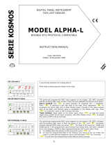
The basic instrument is a soldered assembly composed of
the main board, the display and keyboard module and the
input card.
Extended capabilities are furnished by an optional output
card that incorporates the RS232C and RS485 (RS6)
communication proto
cols and a control card with 2 SPDT
8A relays (2RE).
Each option provides independent connectors protruding
out of the rear of the meter, status LED's visible from the
front and a specific programming module which is
automatically activated once the ca
rd is installed.
The outputs are opto
-
isolated with respect to the input
signal, to the relay outputs and the power supply.
This instrument conforms the following community
standards: 89/336/CEE and 73/23/CEE
WARNING: Refer to the instructions manual to preserve safety protections.
SAMPLING TIME
(TIME)
LESS THAN
.
LIMIT TIME
(LIM)

PROGRAMMING DIAGRAM
TACHOMETER (RPM)
TARE
MAX/MIN
DATA
ENTER
RS232C
RS485
MIN
TARE
PROG
SET 1
SET 2
MAX
F4
F2
F3
F1
FRONT
-
PANEL FUNCTIONS DESCRIPTION (RUN MODE)
22
5 seconds
5 seconds
9
6
LED MAX / F1
Ind
icates peak displayed
LED MIN / F3
Indicates valley displayed
TARE KEY
Takes the display reading a
s tare
DISPLAY
Displays the variable being measured
LED RS485
RS485 selected
KEYBOARD IN RUN MODE
LABEL
Engineering units
KEY DATA
Shows programming data
Gives access
to PROG mode.
MAX/MIN KEY
first push:
Recalls Peak
second push:
Recalls Valley
push 5s :
RESET of Peak or Valley
LED RS32C
RS232C selected
LED TARE / F2
Indicate
s Tare activated
LED PROG / F4
not used in RUN mode
LED SET2
Indicates setpoint 2/ relay 2 activated
TO RS6 OUTPUT
CONFIGURATION
MODULE
TO 2RE OUTPUT
CONFIGURATION
MODULE
TO INPUT
MODULE
CONFIGURATION

The indication shown in figure 21.2 is viewed for 2s before passing to the phase of
programming the number of pulses per revolution (ppr). This value can be set from 0
to 5000 ppr. After 2s or by pressing the ENTER key, the displays
shows the initially
programmed value with the first digit in flash. If it is desired to modify this value,
press repeatedly the
key to vary the flashing digit from 0 to 9, and press
to advance to the next digit to be modified.
Repeat these operations until the
display reads the desired value (from 1 to 5000) and press
ENTER
to save the entry in
the memory and go to the next programming phase. If a value of
ppr
equal to 0 or
greater than 5000 is introduced, the display indicates
Err
for a few seconds and holds
on this programming step to allow modifying the mistaken value.
The figure 21.1 represents the entry level of the display configuration module (
F3
and
PROG
LEDs activated). Press ENTER
to access this module. After the programming
has been completed, the instrumen
t will return to this stage. From here, to go to the
normal operation, press
as many times as to deactivate all the functions LED's
except the PROG one and press ENTER
to store changes in the memory and exit from
the program routine
s.
TARE
MAX/MIN
DATA
ENTER
RS232C
RS485
MIN
TARE
PROG
SET 1
SET 2
MAX
F4
F2
F3
F1
FRONT
-
PANEL FUNCTIONS DESCRIPTION (PROG MODE)
23
[23.2]
Pulses per revolution
TARE
MAX/MIN
DATA
ENTER
RS232C
RS485
MIN
TARE
PROG
SET 1
SET 2
MAX
F4
F2
F3
F1
[23.1] Display configuration
TARE
MAX/MIN
DATA
ENTER
RS232C
RS485
MIN
TARE
PROG
SET 1
SET 2
MAX
F4
F2
F3
F1
MENU F3
TACHOMETER CONFIGURATION (RPM)
7
KEY
Increases the value of flashing
digit
DI
SPLAY
Shows programming parameters
LED RS485
RS485 selected
ENTER KEY
Accepts parameters and values.
Goes to next p
rogramming step.
End programming.
KEY
Shift right
LED F2 / TARE
Module F2: output configuration:
Serial or analog
LED F4 / PROG
Programming mode
KEYBOARD
in PROGRAMMING MODE
LED SET1
programming setpoint
1
LED F1 / MAX
Module F1: Input configuration
LED F3 / MIN
Module F3: Display configuration
LED RS32C
RS232C selected
LED SET2
programming setpoint 2
LABEL
Engineering units

A press of
ENTER
made at previous step gives access to the programming of the
display resolution, preceded, for 2s, by the indication shown in fig. 22.1. This step
offers two options ; The indication "1
" means that the readout will be made without
any decimal place and the indication "
0.1
" means the reading of the display will have
one decimal place. Press the
key to pass from one to other option and, when
the display reads the ind
ication corresponding to the desired resolution, press to
validate the choice and go to the
Pro
level shown in figure 23.1. If it is desired to
have access to the programming of the limit time, instead of pressing the
ENTER
key
at the end of this step, hold it
down for 5 seconds, at the end of which the display will
show the indication given on figure 24.2.
8
24
[24.1] Display resolution
TARE
MAX/MIN
DATA
ENTER
RS232C
RS485
MIN
TARE
PROG
SET 1
SET 2
MAX
F4
F2
F3
F1
The sampling time (see page 19), two digits with decimal point, appears on the
d
isplay after the symbol shown in the left figure.
Make use of the
and
procedure if wanted to modify the initially
programmed value (from 1.0 to 9.9 seconds) and press
ENTER
to save the entry in the
memory and access to the progra
mming of the limit time.
[24.2] Sampling time
TARE
MAX/MIN
DATA
ENTER
RS232C
RS485
MIN
TARE
PROG
SET 1
SET 2
MAX
F4
F2
F3
F1
A press of
ENTER
made at previous step makes the display show the symbol
corresponding to the limit time programming phase (
LIn
) followed, after 2s by the
initially set value with the first of its two digits in flash. If it
is desired to change this
value (see page 17) use the
and
key combination until desired value
(from 1 to 10 seconds) is registered on the display and press
ENTER
to validate the
introduced data and automatically return to the
Pro
stage shown in fig. 23.1.
[24.3] Limit time
TARE
MAX/MIN
DATA
ENTER
RS232C
RS485
MIN
TARE
PROG
SET 1
SET 2
MAX
F4
F2
F3
F1
2. OPERATING INSTRUC
TIONS
PACKING CONTENTS
Instructions manual in English.
The digital panel instrument MICRA
-
F.
Accessories for panel mounting (sealing gasket a
nd fixing
clips).
Accessories for wiring connection (removable terminal
block connectors and fingertip).
Wiring label affixed to the instrument s case. Set of labels
with different engineering units.
Check packing contents.
CONFIGURATION
Power supply (p
ages 9 & 10)
The instruments for 115/230V AC power supply, are set
up at the factory for 230V AC.
(USA market 115 V AC)
.
The instruments for 24/48V AC power supply, are set up
at the factory for 24V AC.
If the instrument is supplied for 12V DC, 24V DC or
48V
DC power supply, it is not necessary to make any change.
Check wiring label before connecting the instrument to
the mains supply.
Programming instructions
(page. 11)
The
software inside the instrument allows configuring the
input parameters. If a 2RE or a RS6 10 option is installed,
the software detects it on power up enabling a specific
routine for its configuration.
Read carefully this paragraph.
Input type (
page 13
-16
)
The instrument provides an input for signals from
transducers like magnetic pick
-
up, encoders, inductive
sensors type NAMUR, PNP,NPN, TTL signals, switches or
AC voltages up to 600V.
Check transducer type and signal level.
Programming lockout (
p
age 21)
As shipped from the factory, the instrument allows full
access to change programming parameters.
To disable the possibility of making changes on the
configuration, it is necessary to remove a plug
-
in jumper
located on the solder side of the displa
y board.
Check jumper position.

25
9
2.1
Power supply and connectors
To change the meter s physical configuration remove the case as
shown in figure 9.1.
115/230 V AC:
The instruments with 115/230 V AC power are
set up at fabrication for 230 V AC (
USA market 115 V AC
), see
figure 9.2. To change
power supply configuration to 115 V AC,
make the jumpers indicated in figure 9.3 and table 1. The wiring
label should be modified to match the new configuration.
24/48 V AC:
The instruments with 24/48 V AC power are set up
at fabrication for 24 V AC, see
figure 9.2. To change power
supply configuration to 48 V AC, make the jumpers indicated in
figure 9.3 and table 1. The wiring label should be modified to
match the new configuration.
12, 24 or 48V DC:
Instruments for DC
power are set up for
the supply voltage
specified in the wiring
label (12V, 24V or 48V
according to the order
reference).
Fig
. 9.1. Disassembly.
Fig. 9.2.
Jumper settings for 230 V or 48 V AC
Fig. 9.3.
Jumper settings for 115 V or 24 V AC
Table 1. Jumper settings.
Pin
1 2 3 4 5
230V AC
-
115V AC
-
48V AC
-
24V AC
-
2.5
Programming lockout
After completing the instrument s programming, it is
recommended to lockout the access to the programming to
prevent from accidental or unauthorized modifications.
This operation is made by taking off a plug
-
in jumper locat
ed
on the solder side of display board circuit (see figure at right).
NOTE :
Disconnect power before changing
the jumper position.
While the instrument is locked out it is however possible to
access to the programming routines to check the current
confi
guration, but it won t be possible to entry or modify data.
In this case, a push of
ENTER
to access the programming
routines will show the indication
dALA
instead of
Pro
.
Display board (solder side)
Remove jumper to lockout the
programming

26
MAX/MIN
. The instrument detects and memorizes the
maximum and minimum values (peak and valley) reached by
the variable after the last reset.
The peak and valley values can be displayed a
t any moment
during normal operation by pressing
MAX/MIN .
The first stroke recalls the peak value and illuminates the
MAX led. The second stroke recalls the valley value and
activates the MIN led.
The third stroke deactivates the led and returns the meter to
the normal reading.
To erase the peak and valley memories, press
MAX/MIN
to
display the value wanted to be eliminated ( MAX and MIN
leds indicate which one is present on display). Press again
MAX/MIN
and hold it for 5s after which the display shows
999
or 9999 indicating th
at the peak or valley memory
respectively has been reset back to these values.
[26.1]
Max. value detected
TARE
MAX/MIN
DATA
ENTER
RS232C
RS485
MIN
TARE
PROG
SET 1
SET 2
MAX
F4
F2
F3
F1
TARE
MAX/MIN
DATA
ENTER
RS232C
RS485
MIN
TARE
PROG
SET 1
SET 2
MAX
F4
F2
F3
F1
[26.2] Min. value detected.
TARE
MAX/MIN
DATA
ENTER
RS232C
RS485
MIN
TARE
PROG
SET 1
SET 2
MAX
F4
F2
F3
F1
[26.3] Reset of Min. value.
10
CONNECTORS
To perform wiring connections, remove
the
terminal block from the meter s connector, strip
the wire leaving from 7 to 10mm exposed and
insert it into the proper terminal while pushing
the fingertip down to open the clip inside the
connector as shown in the figure.
Proceed in the same manner wi
th all pins and plug the terminal block
back to the corresponding meter s connector.
Each terminal can admit wires of section between 0.08 mm² and 2.5
mm² (AWG 26 ÷ 14).
Some terminals have removable adaptors to provide proper fastening for
wires of sectio
ns less than 0.5 mm².
POWER CONNECTION
AC VERSIONS
PIN 1
AC PHASE
PIN 2
GND (GROUND)
PIN 3
AC NEUTRAL
DC VERSIONS
PIN 1
DC POSITIVE
PIN 2
Not connected
PIN 3
DC NEGATIVE
INSTALLATION
To meet the requirements of the directive EN61010
-
1, where the unit
is permanently connected to the mains supply it is obligatory to install
a circuit breaking device e
asy reachable to the operator and clearly
marked as the disconnect device.
WARNING
In order to guarantee the electromagnetic compatibility, the following
guidelines should be kept in mind :
-
Power supply wires may be routed separated from signal wires.
Nev
er run power and signal wires in the same conduit.
-
Use shielded cable for signal wiring and connect the shield to the
ground of the indicator (pin2 CN1).
-
The cables section should be
0.25 mm
2
If not installed and used in accordance with these
instructions
, protection against hazards may be impaired.
3. MEMORY FUNCTIONS
MICRA
-
F provides three keys, all of them are operative in the programmi
ng mode while only
TARE
and
MAX/MIN
can be used in
the run mode. It also provides four LEDs for control functions , two for output status indication and two more for serial
option.

11
Apply pow
er to the instrument, checking previously that it
fits the operating conditions as specified on the label. Once
on power up and after the display test, the instrument is in
(RUN) mode. Press ENTER to go to
Pro
and
F4
LED on.
Thi
s LED will remain on during all programming process.
To return to the run mode, it is necessary to pass through
the different menus with
, until the led F4/ PROG is
the only activated led . Then push
ENTER
. After, it
automatica
lly goes to the normal operating mode .
How to interpret the programming instructions
The programming software routine is composed by a series
of hierarchically organized menus, each allowing the setting
of a specific parameter. In gener
al, the normal sequence at
each step is to push the
key a number of times to
make changes and the
ENTER
key to store them into the
memory and advance to the next step.
The elements used along the programming instructions are
described following.
2.2
Programming instructions
27
4.1. OUTPUT OPTIONS
As an option, the MICRA
-
F models can incorporate the
following output cards: A serial outputs card with
RS232C and RS485 communications protocol, 1200 to
9600 baud half
-
duplex. Both types are included in the
option but only one of them
can be operative as selected
via software.
Ref.
RS6
A control card with 2 SPST relay outputs rating 8A @
250V AC / 150V DC. The option provides four selectable
control modes and selection of pulsecl (with
programmable pulse width) or latched outp
ut for each
relay.
Ref.
2RE
The output options consist of additional cards that are
supplied with their specific instructions manual describing
characteristics, installation, programming and operation.
Once installed in the meter's assembly by me
ans of plug
-
in connectors, a program module is automatically
included in the software routines.
For more detailed information on characteristics,
applications, mounting and programming, please refer to
the specific manual furnished with the option
2 RELAYS
OUTPUT
OPTION
RS232C+RS485
OUTPUT OPTION
4.
OUTPUT
OPTIONS
The programming instructions for each menu step are accompanied by a figure re
presenting the display indication for the
corresponding parameter. Pay special attention to the LED indications and active keys and follow the procedure described on
the text to introduce correctly the desired data.
When the display indication is represent
ed with blank segments, it means that this is one of the possible options of this menu
(normally the default one) depending on the previous selection.
A series of blanked 8 represents any numerical value that can be changed by use of keys
and
(change digit)
and
(change value).
TO THE RS6
OUTPUT
CONFIGURATION
MODULE
TO THE DISPLAY
CONFIGURATION
MODULE
TO THE 2RE OUTPUT
CONFIGURATION
MODULE

12
POWER SUPPLY
AC Voltages
.........
230/115 V, 24/48 V
±10%
50/60 Hz AC
DC Voltages
.....
12 V (10.5 to 16 V) DC, 24 V (21 to 32 V)
...........................
48V (42 to 64 V) DC
Consumption
...........................................................
3 W
FUSES (DIN 41661) Reco
mmended
MICRA
-
F (230/115V AC)
...........................
F 0.1A / 250 V
MICRA
-
F2 (24/48V AC)
.............................
F 0.2A / 250 V
MICRA
-
F3 (12 V DC)
....................................
F 1A / 250 V
MICRA
-
F4 (24 V DC)
................................
.
F 0.5A / 250 V
MICRA
-
F5 (48 V DC)
................................
.
F 0.5A / 250 V
DISPLAY
Type
...............................
9999, 4 red digit 14 mm high
Frequency meter range
............................
0 to 999.9
Hz
Decimal point
........................................
programmable
LEDs
......................
4 for control and 4 for output status
Reading rate
......................................................
< 1/ s
Display over
-
range
................................................
OvE
Input over
-
range
..........................
000 ó OvE (flashing)
ENVIRONMENTAL
Operating temp
.
...
-
10 ºC to +60 ºC
(0 ºC to 50 ºC acc. to UL)
Storage temperature
............................
-
25 ºC
to +85 ºC
Relative humidity( non condensing)
.........
<95 % to 40 ºC
Max altitude
................................................
2000 meters
Indoor use
DIMENSIONS
Dimensions
..............................................
96x48x60 mm
Panel cutout
...................................................
92x45 mm
Weight
..................................................................
250 g
Case material
.........................
polycarbonate s/UL 94 V
-0
5. TECHNICAL S
PECIFICATIONS
28
INPUT SIGNAL
Frequency Max.
.................................................
2 KHz
Frequency Min.
..................................................
0.1 Hz
Excitation
........................
8V @ 30 mA ó 24V @ 30 mA
High voltage input
Input range
....................................
10 to 600 V AC
Magnetic Pick
-
up
Sensitivity
..........................
Vin (AC) > 120 mV eff.
NAMUR sensor
Rc
................................................................
1 K
Ion
.....................................................
< 1 mA DC
Ioff
.....................................................
> 3 mA DC
NPN y PNP type sensor
Rc
................................................
1 K
(included)
Logical level
...........
0 < 2.4 V DC, 1 > 2.6 V DC
TTL/24V DC (encoder)
Logical level
...........
0 < 2.4 V DC, 1 > 2.6 V DC
Contact closure
Vc
..................................................................
5 V
Rc
.............................................................
3.9 K
Fc
..............................................................
100 Hz
Accuracy
Error max
.......................
± (0.01% of reading +1 digit)
Temperature coefficient
............................
100 ppm/ ºC
Warm
-
up time
..............................................
5 minutes

2.3
Input configuration
SW1
1 2 3 4 5
Magnetic Pick
-
up
off
off
on
off
off
NAMUR sensor
on
off
on
on
off
NPN type sensor
on
on
off
off
off
PNP type sensor
on
off
off
on
off
TTL/ 24V (encoder)
on
off
off
off
on
Contact closure (switch)
on
on
on
off
on
Voltage up 600V*
off
off
off
off
off
* Factory configuration
13
29
Before undertaking signal connection, set the input for the sensor type
to be used in the application by means of the SW1 5-
position DIP
switch located on the main board.
F
ollow the indications given in the table:
5.1
-
Dimensions and mounting
To install the instrument into the panel,
make a 92x45mm cutout and insert the
instrument from the front placing the
sealing gasket between this and the front
bezel.
Place the f
ixing clips on both sides of the
case and slide them over the guide tracks
until they touch the panel at the rear side.
Press slightly to fasten the bezel to the
panel and secure the clips.
To remove the instrument from the panel,
pull outwards the fixing
clips rear tabs to
disengage and slide them back over the
case.
CLEANING: The front cover should
be cleaned only with a soft cloth
soaked in neutral soap product.
DO NOT USE SOLVENTS
SEALING
GASKET
FIXING CLIPS
PANEL
CLIPS
RETENTION

CN2
CN2
CN2
CN2
CN2
CN2
1
2
5
3
4
1
2
5
3
4
1
2
5
3
4
1
2
5
3
4
1
2
5
3
4
1
2
5
3
4
Magnetic Pickup
NAMUR Sensor
+ EXC
OUT (Signal)
Contact Closure
NPN or PNP type sensors
+ EXC
OUT (Signal)
-
(GND)
TTL/24V (Encoder)
+ EXC
OUT (Signal)
-
(GND)
High Voltage Input
14
INPUT SIGNAL CONNECTOR (CN2)
PIN 1 =
-
IN
PIN 2 = +IN
PIN 3 = +EXC [24V DC (+)]
PIN 4 = +EXC [8V DC (+)]
PIN 5 = IN [HIGH, 10
-
600V AC]
Input signal connectio
n
Refer to the transducer s specifications and to the wiring
advisements given
in page 10
.
Connection according to the sensor type.
Refer to the transducer s specifications and to the wiring
advisements given
in page 10
.

15
The display presents the initially selected input type :
FrEC
= FREQUENCY METER,
TAC
= TACHOMETER,
rATE
= RATE
METER. Press repeatedly the
key to scroll
around the available options until the desired one appears on the display and press
ENTER to validate the choice and automatically return to the
Pro
stage indicated in
the figure 15.1.
[15.2] Mode selection
TARE
MAX/MIN
DATA
ENTER
RS232C
RS485
MIN
TARE
PROG
SET 1
SET 2
MAX
F4
F2
F3
F1
The figure 15.1 represents the entry level of the input configuration module (
Pro
indication,
F1
and
PROG
LED's activated).
Press
ENTER to enter this module. Once completed the entire pro
gram sequence, the
instrument returns to this stage. To return to the run mode, press the
key
and, when only the PROG LED is activated, press ENTER
to save changes in the
memory and exit from the programming mode.
[15.1] Input to Mode selection
TARE
MAX/MIN
DATA
ENTER
RS232C
RS485
MIN
TARE
PROG
SET 1
SET 2
MAX
F4
F2
F3
F1
MENU F1
MODE SELECTION
31
Mode selection.
This menu allows to choose among three ways of working the instrument , like frequency meter (indic
ation
FrEC
) to measure
frequency, tachometer rpm (indication
TAC
) to measure revolutions per minute and tachometer rate (indication
rATE
) to
measure velocity. All acceptable sensor can be used for any of this described functions.
All products are warranted against defective material and workmanship for a
period of three years from date
of delivery.
If a product appears to have a defect or fails during the normal use within the
warranty period, please contact the distributor from whom you purchased the
product.
This warranty does not apply to defects resulting from action of t
he buyer
such as mishandling or improper interfacing.
The liability under this warranty shall extend only to the repair of the
instrument ; no responsibility is assumed by the manufacturer for any damage
which may result from its use.
.
6.
WARRANTY

INPUT FREQUENCY
(INP1)
The "INP1" parameter refers to the signa
l frequency generated
by the transducer. This frequency must be within the specified
limits (0.1Hz to 2kHz) and can be programmed with two, one or
no decimal place.
DESIRED DISPLAY
(DSP1)
The "DSP1" parameter is the desired display readout
corresponding
to the frequency programmed in the "INP1"
phase.
The decimal point can be located anywhere.
The display variation can be directly proportional to the input
variation (increasing frequency increasing display) or inversely
proportional (increasing frequency
decreasing display) as
selected in the first programmable parameter of the display
module (see page 16) where
dIr
= direct,
Inv
= inverse.
2.4
Display range
configuration
The display range configuration depends on the measurement type selected in the input programming module.
As FREQUENCY METER, the instrument hasn't any configurable scaling parameter. The access to the display programming
module (
F3
LED
illuminated) is not allowed.
As RATE METER, the display configuration module allows programming the input frequency and the desired display at this
frequency. The DISPLAY/FREQUENCY ratio can be selected to be in a direct or inverse proportion.
As TA
CHOMETER (RPM), the only parameter needed to configure the display is the number of pulses per revolution that
delivers the sensor.
To adjust the display to the specific application, the instrument configured as rate meter or tachometer permits the user
to access
to the programming of the limit and sampling time. The access is made by a holding down the ENTER key for 5s before exiting
from the display configuration module.
2.4.1
-
Programming TACHOMETER (RATE)
16
EXAMPLE
It is desired to measure the rate in m/s of a conveyor belt
which is driven by a turning shaft of 20 cms diameter and
300 rpm that gives 4 pulses per revolutio
n.
In 1 second, the shaft gives 20 pulses (300 rpm are 5
revolutions per second and each revolution gives 4 pulses).
The input frequency is then 20Hz.
At this frequency, the rate of the conveyor belt is :
rpm* Pi * d = 300* Pi * 20 = 18849.6 cm/min = 3.14
2 m/s
The INP1 and DSP1 parameters must be :
INP1 = 20
DSP1 = 3.142
The display variation mode with respect to the input
frequency must be directly proportional (
dIr
option).
33

FREQUENCY
METER
RATE
TACHOMETER
-
rpm
TACHOMETER
MODEL MI CRA-F
INSTRUCTION MANUAL
EDITION: January 2001
CODE: 30727016
70
17
With the setting of the INP1 and D
SP1 parameters, the instrument should be able to operate correctly, notwithstanding ,
depending on the sensor characteristics, it may be necessary to modify the internal measurement time.
After, programming the DSP1 item, a push of ENTER
of 5s provides access to the programming of the sampling time TIME
and the LIM .
SAMPLING TIME
(TIME)
With irregular signals, the display may present fluttering or
unwanted variations due to the signal cycles detected at each
reading are not equal.
Th
e TIME parameter allows stretching the measurement
interval, making an average of a larger number of cycles.
This reduces considerably the display fluttering.
The sampling time can be programmed from 0,1 to 9,9
seconds It is factory set at 1 second.
To
help stabilizing the display in case of fast variation input
signals, it is recommended to increase this parameter, taking
into account that the display update time will be the same as
the programmed sampling time.
The sampling time can be reduced to incre
ment the display
update rate.
LIMIT TIME
(LIM)
The limit time, programmable from 1 to 10 seconds, is
applied in order to limit the waiting time for at least 1 pulse is
produced at the input before to be considered to be zero.
If any
pulse has been detected at the input before the end of
the limit time, the input is considered to be zero and the
display reads zero.
The instrument is factory set for a limit time of 10 seconds.
Decreasing the limit time the instrument detects the zero
c
ondition more quickly after the system stops, but this
reduction leads to an increment of the minimum visible
indication that the display can read before going to zero.
Example.
Assume you want to indicate 1000 lit/s with an
input frequency of 1kHz.
With
a limit time of 10s, the minimum frequency is 0,1Hz (as
specified on technical characteristics) and the display readout
at this frequency 0,1lit/s. Since this value would no be
readable in a display of 1000 counts, it is possible to reduce
the limit time t
ill 1s, so that the minimum frequency becomes
1 Hz and the minimum readout before the display shows zero
is 1lit/s.

2
18
PROGRAMMING DIAGRAM
FOR TACHOMETER (RAT
E
)
INTRODUCTION
TO
THE
DITEL
MICRA
SERIES
This manual does not constitute a formal agreement.
All information given in this manual is subject to
change without notice.
DITEL brings a new philosophy in digital panel
instr
umentation by using multipurpose, modular-
co
ncept
devices providing a rich array of basic functions and
advanced cap
a
bilities.
With a fully MODULAR DESIGN, it is possible to implement a
wide variety of applications simply by adding the desired
option(s).
Built
-in intelligence allows the meter to r
ecognize the options
in
stalled and implement the necessary parameters to properly
function within desired parameters. The basic instrument
without output options omits these data in the program
ro
u
tines.
CALIBRATION is performed at the factory eliminating
the
need for adjustment potentiometers. Any circuit or option
liable to be adjusted incorporates a memory where calibration
parameters are stored, making it possible the optional cards
be totally interchangeable without need of any subsequent
adjustments
.
Custom CONFIGURATION for specific applications can be
mad
e quickly and easily through three or five front panel
keys, following structured choice menus aided by display
prompts at each programming step.
Other features of the MICRA family include :
CONNECTIONS via plug
-
in terminal blocks without
screws and CLE
MP
-
WAGO clips cable retention system.
DIMENSIONS
Models ALPHA & BETA 96x48x120 mm DIN 43700
Models JUNIOR, JUNIOR20, & MICRA 96x48x60 mm DIN
43700
CASE MATERIAL UL
-
94 V0
-
rated poly
-
carbonate.
PANEL INSTALLATION by means of single part
fingertip with
out screws.
To guarantee the meter s technical specifications, its is advised
to check calibration parameters
at periodical intervals according
to the ISO9001 standards for the particular application
operating criteria.
Re
-
calibration of the meter should be made at the factory or in
a qualified laboratory.
TO INPUT
MODULE
CONFIGURATION
TO RS
6 OUTPUT
CONFIGURATION
MODULE
TO 2RE OUTPUT
CONFIGURATION
MODULE

DIGITAL PANEL METER
KOSMOS SERIES
MODEL MI CRA
-
F
The first menu option allows selection between two display modes.
The direct mode must be selected where the display and input frequen
cy are to be in
a direct proportion, that is, the greater the frequency the greater the display. The
inverse mode should be used to make the display vary in opposition with the input
frequency, that is as greater the frequency, as smaller the display and v
ice versa.
Press
key to make the display show the desired mode (
dir
= direct,
inv
=
inverse) and press
ENTER
to validate the choice and advance to the next step.
The figure 19.1 represents the entry stage of the display configuration module (
F3
and
PROG
LED activated). Press
ENTER
to access this module.
After the programming has been completed, the instrument will return to this stage.
From here, to go to the normal operation, press
as many times as to
deactivate all the functions LEDs except the PROG one and press ENTER
to save
changes in the memory and exit from the program routines.
The indication shown in figure 17.3 is viewed for 2s before passing to the phase
of programming the input frequency (
InP1
). After 2s or by pressing the
ENTER
key,
the display will show any numerical value (depending on previous settings) with the
first
digit in flash. If desired to modify this value, press the
key to vary the
flashing digit from 0 to 9, and the
key to advance to the next digit to be
modified. Repeat these operations until the display reads the required val
ue and press
ENTER
to save the entry in the memory; The decimal point becomes flashing to
indicate that it is possible to change its position at this program step. Press repeatedly
the
key to move the decimal point until it takes the desired location. If no
decimal point is required, it must be placed to the rightmost digit. Press
ENTER
to
save changes in the memory and advance to the next programming step.
3
INDEX
1 . MODEL MICRA
-
F OVERVIEW
...................................................................................................................
4-5
1.1.
FRONT
-
PANEL DESCRIPTION
...............................................................................................
6-7
2 . SETUP AND OPERATION
............................................................................................................................
8
2.1
POWER SUPPLY AND CONNECTORS
.....................................................................................
9-
10
2.2
PROGRAMMIN
G INSTRUCTIONS
.............................................................................................
11
2.3
INPUT CONFIGURATION
...............................................................................................
13
-
14
-
15
2.4
DISPLAY CONFIGURATION
...............................................................
16
-
17
-
18
-
19
-
20
-
21
-
22
-
23
-
24
2.5
PROGRAMMING LOCK
-
OUT
....................................................................................................
25
3 . MEMORY FUNCTIONS
..............................................................................................................................
26
4. OUTPUT OPTIONS
..................................................................................................................................
27
5 . TECHNICAL SPECIFICATIONS
..................................................................................................................
28
5.1
-
DIMENSIONS AND MOUNTING
................................................................................................
29
19
[19.2] Way of working
TARE
MAX/MIN
DATA
ENTER
RS232C
RS485
MIN
TARE
PROG
SET 1
SET 2
MAX
F4
F2
F3
F1
[19.1] Display configuration
TARE
MAX/MIN
DATA
ENTER
RS232C
RS485
MIN
TARE
PROG
SET 1
SET 2
MAX
F4
F2
F3
F1
[19.3] Frequency value
TARE
MAX/MIN
DATA
ENTER
RS232C
RS485
MIN
TARE
PROG
SET 1
SET 2
MAX
F4
F2
F3
F1
MENU F3
PROGRAMMING INSTRUCTIONS TACHOMETER (RATE)

The sampling time (see page 17), two digits with decimal point, appears on the
display after the symbol shown in the left figure. Make use of the
and
procedure if wanted to modify the initially programmed value (from 1.0 to 9.9
seconds) and press
ENTER
to save the entry in the memory and to access to the
programming of the limit time.
After programming the input frequency, a press of
ENTER
provides access to the
programming of the display desired for this frequency (
dSP1
,) preceded by the
symbol shown in figure 20.1. Proceed as in the section 19.3.(
increments value,
advances to the next digit) to compose the desired value and press t
o set the
decimal point position (by means of the
key). Press again
ENTER
to exit from
the program module and return to the
Pro
stage shown in fig. 19.1.
If it is wanted to have access to the programming of the sampling time or the limit
time, after programming the decimal point location, hold the
ENTER
key for 5
seconds, at the end of which the display will show the indication given in figure 20.2.
A press of
ENTER
made at previous ste
p makes the display show the symbol
corresponding to the limit time programming phase (
LIn
) followed, after 2s by the
initially set value with the first of its two digits in flash. If it is desired to change this
value (see page 15) use the
and
key combination until desired value
(from 1 to 10 seconds) is registered on the display and press
ENTER
to validate the
introduced data and automatically return to the
Pro
stage shown in fig. 19.1.
20
[20.2]
Sampling
time
TARE
MAX/MIN
DATA
ENTER
RS232C
RS485
MIN
TARE
PROG
SET 1
SET 2
MAX
F4
F2
F3
F1
[20.1] Display value
TARE
MAX/MIN
DATA
ENTER
RS232C
RS485
MIN
TARE
PROG
SET 1
SET 2
MAX
F4
F2
F3
F1
[20.3] Limit time
TARE
MAX/MIN
DATA
ENTER
RS232C
RS485
MIN
TARE
PROG
SET 1
SET 2
MAX
F4
F2
F3
F1
4
RS6
OUTPUT OPTION
MAIN
BOARD
CASE WITH PANEL
FIXING CLIPS
FRONTAL COVER
2RE OUTPUT
OPTION
DISPLAY and
KEYBOARD MODULE
/