Page is loading ...

COUNTER
-
CHRONOMETER
INSTRUCTIONS MANUAL
November 2000
CODE: 30727017
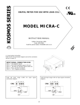
In this program step it is possible to activate a debounce filter with a cut
-
off frequency
of 20Hz.
The f
igure 25.1 shows the indication that appears on the display by a press of
"ENTER" on the previous phase. After 2 seconds or by pressing the "ENTER" key, the
display shows "0" or "1" depending on the initial configuration.
The "0" means filter OFF (the mete
r admits any frequency in the range specified for
the counter) and the "1" means filter ON (it only admits signals of frequency lower
than 20Hz).
Press
if it is desired to change the option present on the display and press
ENTER
to validate the choice and go to the next programming phase.
The next phase (fig. 25.2) is accessible if the display offset programming routine is not
locked out (see section "LOCK
-
OUT FUNCTIONS ROUTINE"). If this parameter is
locke
d out, the instrument returns to the
Pro
stage given on figure 24.1 with data
memory storage.
If the display offset programming is enabled, a press o
f
ENTER
made at previous step
gives access to the programming of the value from which the meter starts counting
after each reset.
The initially programmed value appears on the display with the first digit in flash,
preceeded, for 2 se
conds, by the indication shown on figure 25.2.
Use the procedure described in fig. 24.2 (
changes the flashing digit value,
advances to the next digit to the right) until the desired value is composed
on
the display and press
ENTER
to save data in the memory and return to the
Pro
stage.
Y2K
OK
MODEL MI CRA-I
[25.1]
TARE
MAX/MIN
DATA
ENTER
RS232C
RS485
MIN
TARE
PROG
SET 1
SET 2
MAX
F4
F2
F3
F1
[25.2]
TARE
MAX/MIN
DATA
ENTER
RS232C
RS485
MIN
TARE
PROG
SET 1
SET 2
MAX
F4
F2
F3
F1
25

TO THE DISPLAY
CONFIGURATION
MODULE
TO THE RS OUTPUTS
CONFIGURATION
MODULE
TO THE SETPOINTS
CONFIGURATION
MODULE
2
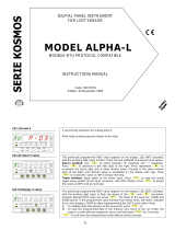
3.3. PROGRAMMING THE CHRONOMETER
CHRONOMETER INPUT PROGRAMMING DIAGRAM
26
I
NTRODUCTION TO THE K
OSMOS SERIES
KOSMOS digital series instruments will w
ork without
problems after 1st of January 2000 since they have no
real time
clock inside or outside the microprocessor.
This manual does not constitute a formal agreement.
All information given in this manual is subject to
change without notice.
The KOS
MOS SERIES brings a new phylosophy in digital
panel instrumentation which is expressed by multipurpose,
modular
-
concept devices providing a rich array of basic
functions and advanced capabilities.
With a fully MODULAR DESIGN, it is possible to implement a
wide variety of applications by only adding the adequate
options.
Intelligence within allows the meter to recognize the options
installed and ask for the necessary parameters to properly
function within desired margins. The paramenters related to
non
-
ins
talled options are removed from the program routines.
The instruments CALIBRATION is made at the factory
eliminating the need for adjustment potentiometers.
Any circuit or option liable to be adjusted incorporates a
memory where calibration parameters are
stored, making it
possible the optional cards be totally interchangeable without
need of any subsequent adjust.
Custom CONFIGURATION for specific applications can be
made quickly and easily through five front pan
el keys,
following structured choice menus aided by display prompts
at each programming step.
Other features of the KOSMOS family include :
CONNECTIONS via plug
-
in terminal blocks without
screws and CLEMP
-
WAGO clips cable retention system.
DIMENSIONS
M
odels ALPHA & BETA 96x48x120 mm DIN 43700
Models MICRA & JR/JR20 96x48x60 mm DIN 43700
CASE MATERIAL UL
-
94 V0
-
rated polycarbonate.
PANEL INSTALLATION without screws by means of
single part fastening clips.
To guarantee the meter's technical specifications, it is recommended
to recalibrate the meter at periodical intervals accordin
g to the
ISO9001 standards for the particular application operating criteria.
Calibration should be perfomed at the factory or in a qualified
laboratory.

DIGITAL PANEL METER
KOSMOS SERIES
MODEL MI CRA-I
3
1.
GENERAL OVERVIEW ON MODEL MIC
RA
-I
1.1. INTRODUCTION
.................................................................................................................................................
5-6
1.2.
COUNTER OPERATION
.......................................................................................................................................
7-8
1.3.
CHRONOMETER OPERATION
................................................................................................................................
.9
1.4.
FRONT
-
PANEL FUNCTIONS
.............................................................................................................................
10
-
11
2.
FIRST OPERATIONS
2.1.
GETTING STARTED
............................................................................................................................................
12
2.2.
POWER SUPPLY
..................................................................................................................................................
13
2.3.
INPUT CONFIGURATION
......................................................................................................................................
14
2.4.
SIGNAL CONNECTION
.........................................................................................................................................
15
3.
PROGRAMMING INSTR
UCTIONS
3.1.
INTRODUCTION
.............................................................................................................................................
16
-
17
3.2.
PROGRAMMING THE COUNTER
3.2.1. INPUT
...........................................................................................................................................
18
-
19
-
20
-
21
-
22
3.2.2. DISPLAY
................................................................................................................................................
23
-
24
-
25
3.3. PROGRAMMING THE
CHRONOMETER
3.3.1. INPUT
....................................................................................................................................................
26
-
27
-
28
3.3.2. DISPLAY
.....................................................................................................................................................
29
-
30
4.
CHARACTERISTICS
4.1.
OUTPUT OPTIONS
...............................................................................................................................................
31
4.2.
TECHNICAL SPECIFICAT
IONS
..............................................................................................................................
32
4.3.
DIMENSIONS AND MOUNTING
.............................................................................................................................
33
[27.1]
TARE
MAX/MIN
DATA
ENTER
RS232C
RS485
MIN
TARE
PROG
SET 1
SET 2
MAX
F4
F2
F3
F1
The figure 27.1 shows the indication corresponding to the entry stage of the input
programming module.
From the run mode, press
ENTER
and
to acceed thi
s level.
Once programmed the last module parameter, the instrument will go back to this
stage. To return to the RUN mode, press repeatedly the
key until all LED's
deactivate except the PROG LED and press
ENTER
.
The meter exits fro
m the
programming mode and goes to the normal operation.
[27.2]
TARE
MAX/MIN
DATA
ENTER
RS232C
RS485
MIN
TARE
PROG
SET 1
SET 2
MAX
F4
F2
F3
F1
A press of
ENTER
made at previous step gives access to the selection of the
meter type : Counter (
COU
indication) or Chronometer (
CHrO
indication).
Press the
key, if necessary, to make the display show the option
CHrO
and
press ENTER to acceed to the programming of t
he chronometer inputs mode (see
page 9).
[27.3]
TARE
MAX/MIN
DATA
ENTER
RS232C
RS485
MIN
TARE
PROG
SET 1
SET 2
MAX
F4
F2
F3
F1
The indication represented in figure 27.3 is displayed for 2 seconds before
entering in the chronometer mode programming phase. After 2 seconds or by
pressing
ENTER
,
the display shows the indication corresponding to the initially
programmed mode:
Ind
= INDEPENDENT,
dIr
= DIRECTIONAL.
Use the
key to select the desired option (page 9) and :
press
ENTER
for 3s to get
access to the lock
-
out functions routine (page 22), or
press briefly the
ENTER
key to validate the choice and automaticaly go to the
Pro
level (fig. 27.1).
27

4
RS232C + RS485
OUTPUT OPTION
MAIN
BOARD
CASE FIXING CLIPS
FRONT
-
PANEL COVER
2 SETPOINTS
OUPUT OPTION
DISPLAY AND
KEYBOARD MODULE
CHRONOMETER LOCK
-
OUT FUNCTIONS
[28.1]
TARE
MAX/MIN
DATA
ENTER
RS232C
RS485
MIN
TARE
PROG
SET 1
SET 2
MAX
F4
F2
F3
F1
The chronometer lock
-
out functions are accessible, from the stage represented in
figure 27.3, by holding down the
ENTER
key for 3 seconds, at the end of wh
ich the
display shows the indication
LOC
given on the left figure. This indication is viewed
for 2 seconds before passing to the phase represented in the next figure, where
the display may show any combination of "0" and "1" (depending on previous
configur
ation) with the first digit in flash.
[28.2]
TARE
MAX/MIN
DATA
ENTER
RS232C
RS485
MIN
TARE
PROG
SET 1
SET 2
MAX
F4
F2
F3
F1
Starting from the
left ;
The 1
st
digit has no function, press
to go to the next digit to the right.
The 2
nd
digit allows to lock out the setpoints programming :
(0=enabled, 1=locked out). Press the
key if wanted to change the value
of the flash
ing digit and the
key to advance to the next digit to the right.
The 3
rd
digit has no function in the chronometer configuration; Press
to
pass to the next one.
The 4
th
digit controls the action of the "RESET" key. One "0" allows to make
reset on the
front panel and one "1" disables this function. Use the
key if
desired to change the digit value, or
if wanted to start the programming
by the first digit and press
ENTER
to validate the introduced data
and return to
the
Pro
level (page 27).
28

1.1.
INTRODUCTION
The MICRA
-
I model is a four
-
digit, small format
instrument with two inputs that admit several types of
sensors and puls
e generators, as selected by DIP
-
SWITCH, to make the functions of :
UP, DOWN and UP/DOWN COUNTER;
with front-
panel and remote RESET, selectable decimal
point, display offset (value to which the counter goes
after each reset), 20Hz debounce filter and poss
ibility of
locking out the RESET button, the setpoints
programming and the offset programming.
CHRONOMETER;
with five time ranges from hundredths of second to
hours, front
-
panel and remote RESET, decimal point
according to scale and possibility of locking
out the
RESET button and the setpoints programming.
The last count registered before a power failure or cut
-
off is saved in an internal memory and restored on the
display on power up.
1. MODEL MICRA
-
I
The basic instrument is a soldered assembly composed
by the main board and the display + keyboard module.
Extended capabilities are furnished b
y the following
optional cards:
Serial communication output card with RS232C and
RS485 protocoles.
Control outputs card with 2 SPDT 8A relays.
The output options give the meter a wide number of
new additional functions and operating modes and also
permit automatic process control and communication
with external devices.
Each option provides independent connectors,
protruding out of the rear of the instrument, status
LED's on the front
-
panel and a specific programming
module which is automatically
activated once the card
is installed.
The outputs are opto
-
isolated with respect to the input
signal.
5
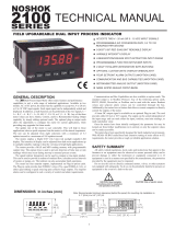
3.
3.2. PROGRAMMING THE CHRONOMETER SCALE
CRONOMETER PROGRAMMING DIAGRAM
29
TO THE INPUT
CONFIGURATION
MODULE
TO THE RS OUPUTS
CONFIGURATION
MODULE
TO THE SETPOINTS
CONFIGURATION
MODULE

VERY IMPORTANT :
THE "2RE" AND "RS6" OPTIONS, CONNECTABLE TO THE MICRA FAMILY, CAN ALSO BE INSTALLED IN THE MICRA
-
I
MODELS TAKING NOTICE OF THE FOLLOWING
INSTRUCTIONS :
FOR THE "2RE" OPTION :
You must refer to pages 8, 9 and 10 to install the card,
make
wiring connections and consult the technical
specifications. Leave out the rest of the pages since
they do not include the programming instructions nor
the functional description of the setpoints with relation
to the MICRA
-
I model. These instructions can
be found
in the annexe at the end of the present manual.
FOR THE "RS6" OPTION :
COMMAND
FUNCTION
TYPE OF
FUNCTION
DITEL
ISO
O
0O
Transmission of the offset value
data
request
D
0D
Transmission of the display value
F
0F
Transmission of the input factor
L1
L1
T
ransmission of the setpoint 1
L2
L2
Transmission of the setpoint 2
M1
M1
Modification of the setpoint 1
changing
parameters
M2
M2
Modification of the setpoint 2
6
CHRONOMETER DISPLAY PROGRAMMING
[30.1]
TARE
MAX/MIN
DATA
ENTER
RS232C
RS485
MIN
TARE
PROG
SET 1
SET 2
MAX
F4
F2
F3
F1
The figure 30.1 shows the indication corresponding to the entry stage of the
display programming module. From the run mode, press
ENTER
and two times
to acceed this level.
Once programmed the last module parameter, the instrument will go back to this
stage. To return to the RUN mode, press repeatedly the
key until all LED's
deactivate except the PROG LED and press "ENTER".
The meter exits from the
programming mode and goes to the normal operation.
Press
ENTER
to acceed to the phase represented in the next figure.
[30.2]
TARE
MAX/MIN
DATA
ENTER
RS232C
RS485
MIN
TARE
PROG
SET 1
SET 2
MAX
F4
F2
F3
F1
The indication given
by figure 30.2 is viewed for 2 seconds before entering in the
chronometer scaling. After 2 seconds or by a press of
ENTER
the display will show
the indication corresponding to the initially programmed scale :
[
0.01
= hundredths of se
cond,
0.1
= tenths of second,
1
= seconds,
M.SS
= minutes and seconds,
H
= hours ].
Press repeatedly the
key to shift around the different options and, when
the desired scale appears on the display, press
ENTER
to save the choic
e in the
memory and automatically go to the
Pro
stage of figure 30.1.
30

1.2. COUNTER OPERATION
In pulse counter configuration, the instrument provides
up counting operation (UP mode), down counting
operation (DOWN mode) or bidirectiona
l counting
operation (UP/DOWN mode) as selected via software.
UP Counter
The counting is made in the up direction from zero or
from the programmed offset. When count rises above
9999, the display indicates overrange (OvE).
DOWN Counter
The instrumen
t starts counting down from the
programmed offset. Counts below zero cause negative
overrange (UndE)
A push of
3 seconds
on the RESET key returns the
counter to zero or to the offset value. The meter starts
counting on the first pulse applied after r
eleasing the
RESET key.
In the UP or DOWN configuration, t
he second meter
input (Input B) can be used to start and stop the
counter (see section 20.2, page 20).
UP Counter with A
-
B inputs
DOWN Counter with A
-
B inputs
The meter increments or decrements the display value
on each pulse applied at the
input A as long as the
input B is held at low level. The counter is stopped by
putting the input B to high level.
Input A
Display
0
Reset
1234 1234560
n+1
n+2 n+3 n+4
n+1 n+2 n+3 n+4
n+5
n+6
n
Display n
Input
A
Display n
Reset
n-1 n-2
n-3 n-4 n-1 n-2 n-3 n-4n-5 n-6
n
Input
A
Display 0
Reset
2 3 3 4 51 20
n+1 n+2 n+3 n+3 n+4
n+5
n+1 n+2
nDisplay n
1
Input
B
Input
A
Display
n
Reset
n-1
n-2
n-3
n-3
n-4
n-5
n-1
n-2
n
Input
B
7
31
4.1. OUTPUT OPTIONS
As an option, the MICRA
-
I models can incorporate the
following output cards : A serial output
s card with
RS232C and RS485 communications protocol, 1200 to
9600 baud half
-
duplex. Both types are included in the
option but only one of them can be operative as selected
via software.
Ref.
RS6
A control card with 2 SPST relay outputs rating 8A @
250
V AC / 150V DC. The option provides four selectable
control modes and selection of impulsional (with
programmable pulse width) or latched output for each
relay.
Ref.
2RE
The output options consist of additional cards that are
supplied with their speci
fic instructions manual describing
characteristics, installation, programming and operation.
Once installed in the meter's assembly by means of plug
-
in connectors, a program module is automatically
included in the software routines.
For more detailed infor
mation on characteristics,
applications, mounting and programming, please refer to
the specific manual furnished with the option
2 RELAYS
OUTPUT
OPTION
RS232C+RS485
OUTPUT OPTION
4.
CHARACTERISTICS

BIDIRECTIONAL COUNTER
The bidirectional counter can count in the up or
in the
down direction depending on a combination of its A and B
inputs. It starts counting from zero or from a
programmable offset.
The display limits are
-
9999 and 9999, out of which the
instrument goes to negative overrange (
-
OvE) or positive
overrange
(+OvE) respectively. The positive values are
indicated by the "UP" LED and the minus sign by the
"DOWN" LED.
There are three selectable modes for the UP/DOWN
counter :
Independent UP/DOWN Counter
The A and B inputs are independent. Pulses applied at
the A
input increment the counter and pulses on the B
input decrement the counter.
Directional UP/DOWN Counter
Pulses applied at the A input increment the counte
r
while B is at high level and decrement the counter if B
is at low level.
UP/DOWN Phase Counter
The counter changes its direction each time the input
signal changes its phase.
In the diagrams given on this page and on page 7, the display values are represented in the cases where the counter
starts from zero ( Display 0 ) and from the programmed offset n ( Display n ). The offset programming can be locked
-
out via software (se
e page 22).
For every counter type and counting direction, it is possible to multiply the number of input pulses by a programmable
factor between 0.001 and 9.999 (see page 24).
8
4.2. TECHNICAL SPECIFICATIONS
INPUT SIGNAL
Maximum frequency
Without 2 relay option
...........................................
2KHz
With 2 relay option
................................................
1KHz
UP/DOWN counter (independent mode)
...............
500Hz
Excitation
...........................
8V @ 30mA or 24V @ 30mA
Common mode max. voltage (signal / power supply) :
A
C power
................................
1000V DC / 1500V ACpp
DC power
.....................................................
±400V DC
Magnetic pickup
Sensitivity
...................................
Vin (AC) > 120mV eff.
NAMUR
Rc
............................................................................
1K
Ion
...............................................................
< 1mA DC
Ioff
..............................................................
> 3mA DC
TTL/24V DC (encoder)
Logic levels
......................
"0" < 2.4V DC, "1" > 2.6V DC
NPN and PNP sensors
Rc
.....................................................
1K (incorporated)
Logic levels
......................
"0" < 2.4V DC, "1" > 2.6V DC
Contact closure
Vc
............................................................................
5V
Rc
.........................................................................
3.9K
Fc
........................................................................
20Hz
POWER SUPPLY
AC voltages
..........
115/230V, 24/48V (±10%) 50/60Hz
DC voltages
..
12 V DC (10.5 a 16V), 24V DC (21 a 32V)
Power consumption
..............................................
3W
DISPLAY
Type
................................
9999,4 digits red LED14mm
LED
's
...................
4 for control and 4 for output status
Chronometer scales
....
5 escalas, from 99.99s to 9999h
Counter scale
...............
programmable multiplier factor
Overrange (+) indication
OvE (Up), +OvE (Up/Down)
Overrange ( ) indication
UndE (Down),
-
OvE (Up/Down)
ACCURACY
Temper
ature coefficient
............................
100 ppm/ C
Warm
-
up time
.............................................
5 minutos
ENVIRONMENTAL
Operating temperature
.........................
-
10 C to +60 C
Storage temperature
............................
-
25 C to +85 C
Relative humidity (non condensing)
.......
<95% to 40 C
MECHANICAL
Dimensions
...........................................
96x48x60mm
Weight
...............................................................
250g
Case material
.....................
polycarbon
ate s/UL 94 V
-0
Degree of protection
...........................................
IP65
32

1.3. CHRONOMETER OPERA
TION
The chronometer accumulates time intervals elapsed
between two START and STOP signals until a manual,
automatic or remote RESET returns it to zero.
The t
ime measurement can be realized in any of the five
available scales ; 99.99s, 999.9s, 9999s, 99min59s or
9999h.
The scale is selected in the display programming module
(see pages 29 and 30).
If the time counting exceeds from the limits of the
selecte
d scale, the instrument starts the cycle again from
zero.
The RESET by keyboard must be held for at least
3
seconds
to be effective. The remote RESET is
instantaneous. The reset function can be locked out via
software (see page 28).
The start and stop inputs can operate in two modes as
selec
ted by software (see section 20.2 page 20) :
Independent Mode
The chronometer starts on a rising edge of the A input
and stops on the next falling edge.
Direct Mode
The chronometer starts on a rising edge of the A input
and stops on the next rising
edge of the B input. The A
and B inputs must be configured for TTL / 24V operation
(page 14).
t1+t20t3
0
0
t1t1
t1t2t3
t1t2t3
Input A
9
4.3. DIMENSIONS (mm) AND MOUNTING
33
SEALING GASKET
CLIPS RETENTION
FIXING CLIPS
PANEL CUTOUT
To install the instrument into the panel, make a
92x45mm cutout and insert the instrument into
the panel from the front, placing the sealing
gasket between this and the front bezel.
Place the fixing clips on both sides of the case and
slide them
over the guide tracks until they touch
the panel at the rear side.
Press slightly to fasten the bezel to the panel and
secure the clips at the retention protrudings.
To take the instrument out of the panel, pull
outwards the rear tabs of the fixing clips
to
disengange and slide them back over the case.

10
2
3
4
5
6
7
8
9
10
11
12
13
1
All products are warranted against defective material and workmanship for a
period of three years from date of delivery.
If a product appears to have a defect or fails during the normal use within the
warranty period, please contact the distributor from whom you purchased the
product.
This warranty does not apply to defects resulting from action of the buyer
suc
h as mishandling or improper interfacing.
The liability under this warranty shall extend only to the repair of the
instrument ; no responsibility is assumed by the manufacturer for any damage
which may result from its use.
6. WARRANTY

1.4. FRONT
-
PANEL FUNCTIONS
N
Description
RUN
mode function
PROG mode function
1
LED RS232C
RS232C output selected
Programming of the RS232C output
2
LED RS485
RS485 output selected
Programming of the RS485 output
3
LED SET2
Indicates activation of the SET2 relay
Indicates programming of the setpo
int 2
4
LED OFFS / F2
Indicates that an offset has been programmed
Indicates programming of the serial outputs
5
LED PROG / F4
-
Indicates programming mode
6
LABEL
Measurement unit
7
KEY
ENTER
Enters in PROG mode. Displays data
Ac
cepts data. Advances the programming
8
KEY
-
Displacement to the right
9
RESET KEY
A press of 3 seconds restarts the meter to the
initial conditions
Increments value. In conjunction with
ENTER, allows programming the setpoints
10
DISPLAY
Displays data
Displays programming parameters
11
LED DOWN / F3
Indicates negative values
Indicates scale programming
12
LED UP / F1
Indicates positive values
Indicates input programming
13
LED SET1
Indicates activation of the SET1 relay
Ind
icates programming of the setpoint 1
11
Manufacturer :
DITEL
-
Diseño
s y Tecnología S.A.
Address :
Travessera de les Corts, 180
08028 Barcelona
ESPAÑA
Declares, that the product :
Name :
Digital panel meter
Model :
MICRA
-I
Conforms to :
EMC 89/336/CEE
LVD 73/23/CEE
Applicable Standars :
EN50081
-
1
Generic emission
EN55022/CISPR22
Class B
Applicable St
andars :
EN50082
-1
Generic immunity
IEC1000
-4-2
Level 3
Criteria B
Air Discharge 8kV
Contact Discharge 6kV
IEC1000
-4-3
Level 2
Criteria A
3V/m 80..1000MHz
IEC1000
-4-4
Level 2
Criteria B
1kV Power Lines
0.5kV Signal Lines
Applic
able Standars :
EN61010
-1
Generic Safety
IEC1010
-1
Installation Category II
Transient Voltages <2.5kV
Pollution Degree 2
Conductive pollution excluded
Insulation Type
Enclosure :
Double
Inputs/Outputs :
Basic
7. DECLARATION OF CO
NFORMITY
Date:
17 June 1999
Signed: José M. Edo
Charge: Technical Manager

12
MICRA
-
I
ANNEXE : PROGRAMMING AND OPERATION OF THE
2RE
OPTION
TABLE OF CONTENTS
Functional description
................................................
34
UP COUNTER diagrams
..............................................
35
DOWN COUNTER diagrams
........................................
36
UP/DOWN COUNTER diagrams
...................................
37
CHRONOMETER diagrams
..........................................
38
PROGRAMMING THE 2RE OPTION
Programming diagram. Description
.......................
40/ 41
Programming the setpoint values
................................
42
Programming the operat
ing modes
.......................
43/ 44
If it is necessary to change an
y of the meter's hardware
configurations, insert a screwdriver into the slots on each side of
the case and push until the lips disengange. Lift out the
electronics assembly from the case by pulling outwards as
indicated (see figure 9.1.)
115/ 230V AC : The
instruments that are to be powered with
115/230V AC are set up at fabrication for
230V
operation, see
figure 9.2. To change to 115V, plug in power jumpers indicated
in table 1 as shown in figue 9.3.
24/ 48V AC : The instruments that are to be powered wit
h
24/48V AC are set up at fabrication for
24V
operation, see figure
9.3. To change to 48V,
plug in power jumpers indicated in table
1 as shown in figue 9.3.
Fig. 9.1. Disambling
.
Fig. 9.2. Power jumper position for 230V or 48V AC
Fig. 9.3. Power jump
er position for 115V or 24V AC
Table 1. Jumper positions.
Pin
1 2 3 4 5
230V AC
-
115V AC
-
48V AC
-
24V AC
-
12V DC or 24V
DC
:
The instruments for
operation with DC
power
are supplied for the
voltage specified in the
wiring label (12V or
24V DC).

13
2.3. POWER CONNECTION
CONECTORS
AC VERSIONS
PIN 1 = AC HI (PHASE)
PIN 2 = GND (GROUND)
PIN 3 = AC LO (NEUTRAL)
DC VERSIONS
PIN 1 = DC POSITIVE
PIN 2 = GND (GROUND)
PIN 3 = DC NEGATIVE
To perform wiring connections, remove the
terminal block from the meter's connector, strip
the wire leaving from 7 to 1
0mm exposed and
insert it into the proper terminal while pushing
the fingertip down to open the clip inside the
connector as indicated in the figure. Proceed in
the same manner with all pins and plug the
terminal block into the corresponding meter's
connec
tor.
Each terminal can admit cables of section
comprised between 0.08mm and 2.5mm (AWG
26 ÷ 14).
The blocks are shipped with removable
adaptors inserted in each terminal to provide
proper
fastening for cables of sections less than
0.5mm
2
.
OPERATING MODES : DESCRIPTION
The 2 re
lay option (supplied independently) provides the
instrument with a totally programmable control module
that gives aporta additional working modes and relay
outputs. The reference of this option is 2RE.
IMPORTANT
ANY "2RE" OPTION CAN BE INSTALLED IN THE MI
CRA
-
I
MODELS TAKING NOTICE OF THE FOLLOWING
INSTRUCTIONS :
You must refer to pages 8, 9 and 10 to install the card,
make wiring connections and consult the technical
specifications. Leave out the rest of the pages since they
do not include the programming
instructions nor the
functional description of the setpoints with relation to the
MICRA
-
I model. These instructions can be found in the
present annexe.
The 2RE programming routines allow to configure the setpoint
values, the type of each relay output (impulsional with
programmable pulse width, or latch
ed) and one of the following
four control modes :
Mode 1
Both relays energize when the display reaches the setpoint
value. The counter goes on until a RESET is produced.
The RESET deactivetes the relays (if they are still ON) and
returns the meter to the O
FFSET value.
Mode 2
Both relays energize when the display reaches the setpoint
value. The counter stops on the setpoint 2.
One RESET deactivates the relays (if they are still ON) and
brings the meter to the indication of the OFFSET value.
Mode 3
Both relay
s energize when the display reaches the setpoint
value. The RESET is automatically made when the display
reaches the setpoint 2 which also deactivates the relays (if they
are still ON) and brings the meter to the indication of the
OFFSET value.
Mode 4
The
relay 1 is activated on the setpoint 1 and deactivated on
the setpoint 2. The counting goes on until a RESET makes the
instrument return to the OFFSET value.
When overrange occurs, the relays are held at their previous
state until a reset action.
34

UP COUNTER FUNCTIONAL DIAGRAMS
9999
Set2
Set1
Display
Out1
Out2
Reset
OvE
9999
Set2
Set1
Display
Out1
Out2
Reset
offset
OvE OvE
9999
Set2
Set1
Display
Out1
Out2
Reset
offset
OvE OvE
9999
Set2
Set1
Display
Out1
Out2
Reset
OvE
Both impulsional mode ( ) and latched mode ( ) are represented for each relay output (Out1 and Out2).
Mode 1
Mode 3
Mode 2
Mode 4
35
2.3. INPUT CONFIGURATION
Main circuit R
EF. 430 (component side)
Input A
Input B
Before applying the input signal, set the SW1 switches
according to the type of sensor that is to be connected to
the A input, and the SW2
switches for the input B.
SW1 (A) and SW2 (B)
1 2 3 4 5
Magnetic pickup
off
off
on
off
off
NAMUR sensor
on
off
on
on
off
TTL/24V (Encoder)
on
off
off
off
on
NPN sensor
on
on
off
off
off
PNP sensor
on
off
off
on
off
Contact closure
on
on
on
off
on
Select the exc
itation supply by means of the J1 jumper.
EXCITATION
JUMPER J1
8V DC
1-2
24V DC
2-3
14

DOWN COUNTER FUNCTIONAL DIAGRAMS
9999
Set2
Set1
Display
Out1
Out2
Reset
UndE
offset
0
9999
Set1
Set2
Display
Out2
Out1
Reset
UndE
offset
0offset
9999
Set1
Set2
Display
Out2
Out1
Reset
UndE
offset
0offset
9999
Set1
Set2
Display
Out2
Out1
Reset
UndE
offset
0
Mode 1
Mode 2
Mode
3
Mode 4
36
2.4. INPUT SIGNAL CO
NNECTION
COUNTER
When using the two inputs for counting UP and DOWN,
the main sensor must be connected to the A input and
the secondary sensor (signal that
determines the UP or
DOWN direction) to the B input. If only one input is to be
used, this must be the A input.
MAGNETIC PICKUP & NAMUR SENSOR
CONTACT CLOSURE
NPN and PNP SENSORS TTL/24V DC (ENCODER)
1
2
3
4
5
CN2
principal
+EXC
OUT
secundario
+EXC
OUT
1
2
3
4
5
CN2
principal
secundario
reset reset
1 2 3 4 5
CN2
COMUN Encoder
+EXC
OUT2
1 2 3 4 5
CN2
principal
secundario
OUT1OUT1
+EXC
OUT
COMUN
+EXC
OUT
COMUN
reset reset
CN2 CONNECTION
PIN 1 = IN (COMM)
PIN 2 = +IN A
PIN 3 = +IN B
PIN 4 = +EXC (8V/24V
)
PIN 5 = RESET
CHRONOCHRONOMETER
(Inputs configured for TTL/24V)
[A = START, B = STOP]
[A on = START / A off = STOP]
1 2 3 4 5CN2.
START
STOP
RESET
1 2 3 4 5CN2.
START/STOP
RESET
15
Both impulsional mode ( ) and latched mode ( ) are represented for each relay output (Out1 and Out2).

UP/DOWN COUNTER FUNCTIONAL DIAGRAMS
9999
Set2
Set1
Display
Out1
Out2
Reset
-9999
offset
-OvE
9999
Set2
Set1
Display
Out1
Out2
Reset
-9999
offset
9999
Set2
Set1
Display
Out1
Out2
Reset
-9999
offset
9999
Set2
Set1
Display
Out1
Out2
Reset
-9999
offset
-OvE
Mode 1
Mode 2
Mode 3
Mode 4
37
PROG
RAMMING LOCK
-
OUT.
Once the instrument's programming has been
completed, it is recommended to lockout the access to
prevent from accidental or unauthorized modifications.
The locking is made by taking off a plug
-
in jumper
located at the rear side of the dis
play (see figure).
NOTE :
Remove power before changing the jumper
position.
While the instrument is locked out, it is however possible
to acceed to the programming routines to check the
current configuration, but it won't be possible to entry or
modify
data. In this case, the
Pro
indication is
substituted by
dALA
.
3.1. INTRODUCTION
Connect the instrument to the mains supply. For a few
seconds the display illuminates all segments, decimal
points and LEDs as a te
st of their correct functionning.
After, in absence of input signal, the display shows the
last registered value. If the instrument is to be used for
the first time, this vlaue is zero.
To enter in the programming mode, press
ENTER
;the
PROG
LED activates and the display indicates
Pro
.
This is the programming entry stage from which it is
possible to acceed to the input configuration module (
F1
LED activates), display configuration module (
F3
LED
activates) and, if present, to the serial
outputs module
(
F2
LED activates) or the setpoints module (
SET1
and
SET2
LEDs activate).
The access from one to other of the programming
modules is made by pressing the"
" key until the
LED corresponding to the desired function activates. A
press of
ENTER
gives access to the configuration of the
parameters in this menu.
The normal sequence at each step is to push the"
"
key a number of times to make changes and the
ENTER
key to store them in the memory and advance
to the
next step.
The figures are arranged so that they follow this normal
sequence, where the indication with filled
-
out segments
means that the display may show this option or another
depending on the
previous choice.
PROGRAM
LOCK
-
OUT
JUMPER = OFF
Display circuit (solder side)
16
3.
PROGRAMMING
INSTRUCTIONS
Both impulsi
onal mode ( ) and latched mode ( ) are represented for each relay output (Out1 and Out2).

38
CHRONOMETER FUNCTIONAL DIAGRAMS
9999
Set2
Set1
Display
Out1
Out2
Reset
9999
Set2
Set1
Display
Out1
Out2
Reset
9999
Set2
Set1
Display
Out1
Out2
Reset
9999
Set2
Set1
Display
Out1
Out2
Reset
Mode 1
Mode
2
Mode 3
Mode 4
COUNTER PROGRAMMING
In the input configurati
on module (page 18) select the
COU
option (counter) to get access to the following parameters :
Decimal point location.
Counter direction (up, down or bidirectional counting).
Operating mode (see pages 7 and 8).
and, with indirect access (press of
ENTER
of 3s) :
Lock-
out functions for the RESET key, the offset programming
and the setpoints programming (see page 22).
Once the instrument has been programmed as a counter, the
display configuration module (page 23) allows to c
hange its
basic functionning by means of the following options :
Input multiplier factor from 0.001 to 9.999.
For example, if it is desired that the display varies 1 count as
the input receives 10 pulses, the multiplier factor must be 0.100
Debounce
filter with 20Hz cut
-
off frequency.
CHRONOMETER PROGRAMMING
In the input configuration module (page 26) select the
CHrO
option (chronometer) to have access to the following
parament
ers:
START and STOP signals operating mode (see page 9).
and,with indirect access (press of
ENTER
of 3s) :
Lock-
out functions for the RESET key and the setpoints
programming (see page 28).
In the display configuration modul
e (page 29), it will be
necessary to select one of the following time ranges :
Hundredths of second (99.99s).
Tenths of second (999.9s).
Seconds (9999s)
Minutes and seconds (99min59s)
Hours (9999h).
PROGRAMMABLE PARAMETERS OF MODEL MICRA
-
I
17
Both impulsional mode ( ) and latched mode ( ) are represented for each relay output (Out1 and Out2).

3.2. PROGRAMMING THE COUNTER
TO THE DISPLAY
CONFIGURATION
MODULE
TO THE RS OUTPUTS
CONFIGURATION
MODULE
TO THE SETPOINTS
CONFIGURATION
MODULE
7.
SETPOINT PROGRAMMING
MODEL MICRA
-I
18
COUNTER INPUT PROGRAMMING DIAGRAM

The figure 19.1 shows the indication corresponding to the entry stage of the input
programming module.
From the run mode, press
ENTER
and
to acceed this level.
Once programmed the last module parameter, the instrument will go back to this
stage. To return to the RUN mode, press repeatedly the
key until all LED's
deactivate except the PROG LED and press ENTER
The meter exits from the
programming mode and goes to the normal operation.
A press of
ENTER
made at previous step allows access to the selection of the meter
type : counter (
COU
indication) or chronometer (
CHrO
indication).
Press the
key, if necessary, to make the display indicate
COU
and press
ENTER to enter in the p
rogramming routine corresponding to the counter
configuration.
The first menu step is the decimal point location. The indication shown i
n figure 19.3
appears for 2 seconds before this item is allowed to be changed.
After 2s or by pressing the
ENTER
key, the display shows "0000" with the decimal
point in its previously selected position.
Press repeatedly the
key to s
hift the decimal point to the right until it gets the
desired position and press ENTER
to validate the entry and pass to the phase
represented in figure 20.1.
MODEL MICRA
-
I SETPOINTS PROGRAMMING
DIAGRAM
TO THE INPUT
CONFIGURATION
MODULE
TO THE DISPLAY
CONFIGURATION
MODULE
TO THE RS OUTPUTS
CONFIGURATION
MODULE
40
3.2.1. PROGRAMMING THE COUNTER INPUT
[19.1]
TARE
MAX/MI
N
DATA
ENTE
R
RS232C
RS485
MIN
TARE
PROG
SET 1
SET 2
MAX
F4
F2
F3
F1
[19.2]
TARE
MAX/MI
N
DATA
ENTE
R
RS232C
RS485
MIN
TARE
PROG
SET 1
SET 2
MAX
F4
F2
F3
F1
[19.3]
TARE
MAX/MI
N
DATA
ENTE
R
RS232C
RS485
MIN
TARE
PROG
SET 1
SET 2
MAX
F4
F2
F3
F1
19

This program phase allows to select the counter direction. The figure shows one of the
possible options :
UP
= UP counter,
DO
= DOWN counter and
UP.DO
= UP/DOWN
(bidirectional) counter. The three options alternate
on the display by successively
pressing the
key. When the indication corresponding to the desired option
appears on the display, press
ENTER
to validate the choice and advance to the next
program step.
PROGRAMMING THE 2RE OPTION
DEFINITION.
The diagram represented on page 40 shows the setpoints programming module, which is valid for the MICRA
-
I models
with 2RE option installed.
The programmable parameters of th
is option are the following :
The setpoint values, programmable from -
9999 to 9999 for the UP/DOWN counter and from 0 to 9999 for the other
configurations.
The control mode (see pages 34 to 38).
The type of each relay output ; IMPULSIONAL OUTPUT wit
h programmable pulse width (0.1s to 9.9s) or LATCHED
OUTPUT with deactivation on a reset.
ACCESS TO THE PROGRAMMING OF THE SETPOINT VALUES.
The setpoint values are directly accessed from the
Pro
level in any of the programming modules (hidden lines in th
e
diagram, page 40).
From the run mode, press
ENTER
to get access to the programming mode and press"
" to enter in the first setpoint
programming phase. Follow the programming instructions given on page 42.
This routine can not be locked out by hardware with the rest of the programming routines as indicated on page 16 of the
MICRA
-
I manual.
To prevent from incidental or unauthorized modifications of the setpoint values, the instrument provides a software menu
including several lock
-
out functions. This menu is contained in the input programming module (see manual of MICRA
-
I).
ACCESS TO THE PROGRAMMING OF THE CONTROL MODE.
From the run mode, press
ENTER
to acceed to the programming mode ;
the display indicates
Pro
and the
PROG
LED
illuminates.
Press repeatedly the
key until the
SET1
and
SET2
LED's activate.
A press of
ENTER
at this step provides access to the programming of the relays functi
onal parameters according to pages
43 and 44.
This routine can be locked out by jumper with the rest of the programming (refer to the MICRA
-
I manual).
41
IF "UP" or "DO" HAVE BEEN SEL
ECTED ...
In case you have selected one of the uni
-
directional counting options ("UP" or "DOWN"), the next program step offers
two options; "A" for using one meter input and "A
-
b" for using the two inputs, in order to operate the counter in one of
the foll
owing modes (see page 6):
[20.1]
TARE
MAX/MI
N
DATA
ENTE
R
RS232C
RS485
MIN
TARE
PROG
SET 1
SET 2
MAX
F4
F2
F3
F1
[20.2]
TARE
MAX/MI
N
DATA
ENTE
R
RS232C
RS485
MIN
TARE
PROG
SET 1
SET 2
MAX
F4
F2
F3
F1
TARE
MAX/MI
N
DATA
ENTE
R
RS232C
RS485
MIN
TARE
PROG
SET 1
SET 2
MAX
F4
F2
F3
F1
By pressing the
key, the display alternates between the "A" and "A
-
B" indications. Use this key if desired to change the
option present on display and, from this level :
A push of 3 seconds on the
ENTER
key gives access to the lock
-
out functions routine (go to page 22).
A push of ENTER
of less than 3 seconds returns the meter to the
Pro
stage (fig. 19.1).
The input A
receives the
pulses that
increment or
decre
ment the
counter.
The input A
receives the
pulses and the
input B starts or
stops the
counter.
20
/