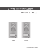
KomelCo DT602 This product is a digital 2-wire intercom system, that supports connection of multiple door stations and monitors in one system. The DT602 allows for setting a unique ID for each door station, enabling the system to handle up to four separate entrances. The system supports electric door locks with two modes of operation: power-on-to-unlock (default setting) and power-off-to-unlock, making it compatible with various types of locks. The device provides customizable settings, including unlock delay time and ringback tone, allowing you to adjust the system's behavior to your preferences.
KomelCo DT602 This product is a digital 2-wire intercom system, that supports connection of multiple door stations and monitors in one system. The DT602 allows for setting a unique ID for each door station, enabling the system to handle up to four separate entrances. The system supports electric door locks with two modes of operation: power-on-to-unlock (default setting) and power-off-to-unlock, making it compatible with various types of locks. The device provides customizable settings, including unlock delay time and ringback tone, allowing you to adjust the system's behavior to your preferences.


-
 1
1
-
 2
2
-
 3
3
-
 4
4
-
 5
5
-
 6
6
-
 7
7
-
 8
8
-
 9
9
-
 10
10
-
 11
11
-
 12
12
-
 13
13
-
 14
14
-
 15
15
-
 16
16


KomelCo DT602 This product is a digital 2-wire intercom system, that supports connection of multiple door stations and monitors in one system. The DT602 allows for setting a unique ID for each door station, enabling the system to handle up to four separate entrances. The system supports electric door locks with two modes of operation: power-on-to-unlock (default setting) and power-off-to-unlock, making it compatible with various types of locks. The device provides customizable settings, including unlock delay time and ringback tone, allowing you to adjust the system's behavior to your preferences.
Ask a question and I''ll find the answer in the document
Finding information in a document is now easier with AI