Extron electronics SW HD 4K Series User manual
- Type
- User manual

SW HD 4K Series • Setup Guide
The Extron SW HD 4K Series are two and four input HDMI switchers for 4K video signals. They are designed for 4K signal
switching between multiple HDMI source devices to a single display. The switchers support computer and video resolutions up
to 4K and 1080p/60 with Deep Color, as well as data rates up to 10.2 Gbps, 3D, Lip Sync, and HD lossless audio formats. All
models feature EDID Minder
®
, which maintains continuous EDID communication with connected devices and ensures that the
HDMI sources power up properly and maintain correct video output. The switchers provide automatic input cable equalization up
to 25 feet (7.6 meters) of Extron HDMI Pro Series cable when a 300 MHz signal input signal is applied (100 feet with 165 MHz).
The SW HD 4K Series offers front panel USB and rear panel RS‑232, IR, contact closure, and auto‑input switching control options
for integration into various environments. This guide provides instructions for an experienced installer to set up and operate these
switchers.
For full installation, conguration, and operation details, see the SW HD 4K Series User Guide, available at www.extron.com.
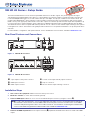
Rear Panel Features and Connections
0.5A MAX
POWER
12V
SW2 HD 4K
1 2
INPUTS OUTPUT
Tx Rx G
GC T
G
1
2
C T
+V
RS-232 AUTO
CONTACT IN/TALLY OUT
REMOTE
E
A
DCB
F
D
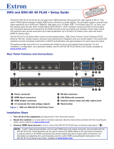
Figure 1. SW2 HD 4K Rear Panel
0.5A MAX
POWER
12V
SW4 HD 4K
1
Tx Rx G
GC T GC
G
1
2
3
4
C T TGC
T +V
RS-232 AUTO
CONTACT IN/TALLY OUT
2 3 4
INPUTS
OUTPUT
REMOTE
E
A
CB D
D F
Figure 2. SW4 HD 4K Rear Panel
Installation Steps
1. Turn off all of the equipment and disconnect it from the power source.
2. Mount the switcher on a rack shelf or furniture (optional).
3. Connect HDMI input sources to one or more of the SW HD 4K input connectors (see gures 1 and 2,
B
).
NOTE: LockIt
®
cable lacing brackets, one for each HDMI input and output connector, are provided with the SW HD 4K.
These brackets can be used to secure the HDMI cables to the rear panel connectors to reduce stress on the HDMI
connectors and prevent signal loss due to loose cable connections. For information on attaching the LockIt brackets,
see the LockIt HDMI Lacing Bracket Installation Guide card, available at www.extron.com.
4. Connect an HDMI output device to the output connector (
C
). By default, the EDID of this device is stored at the HDMI
output.
A
2‑pole captive screw power connector
D
Contact closure input and tally output connectors
B
HDMI input connectors
E
Tally +V connectors
C
HDMI output connector
F
RS‑232 and auto‑input switching connectors
Product Category
1

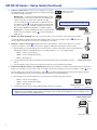
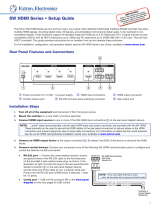
5. Connect control devices. Connect your computer to one of the
following SW HD 4K communication ports to congure and control
the switcher via SIS commands:
• RS-232 port — Connect the unterminated transmit, receive,
and ground wires of the RS‑232 cable to the provided 3‑pole
captive screw plug, as shown in the illustration at right.
Connect the plug to the rear panel Remote shared connector
(see gures 1 and 2,
F
, on the previous page), and the other
end of the cable to your computer serial port. Protocol for the
RS‑232 port is 9600 baud, 8 data bits, 1 stop bit, no parity.
• Config port — Connect a USB mini‑B cable to the front panel
USB connector (see gures 4 and 5,
C
, on the next page) for
USB control.
6. Enable auto-input switching (optional). Use a jumper wire to connect the pins of the shared 2‑pole captive
screw plug. Attach the plug to the remote RS‑232/Auto switch connector (see gures 1 and 2,
F
) if this was not
done in step 5 for the RS‑232 connection (see the diagram to the right).
7. Connect a contact closure device (optional). Connect a push‑button contact closure device to a Contact
connector (see gures 1 and 2,
D
, on the previous page) to enable input switching via contact closure.
a. Wire and plug one of the provided 3‑pole connectors into a Contact In/Tally Out connector representing the
desired input number on the SW HD 4K (1 or 2 for SW2 models, 1, 2, 3, or 4 for SW4 models).
• Pin 1 = Contact closure input (C)
• Pin 2 = Contact and Tally Ground (G)
• Pin 3 = Tally output (T)
b. Insert the ground wire of the contact device into the Ground slot of the Contact/Tally connector
(pin 2).
c. Press the button on the contact closure device to switch the connected input to the output.
8. Connect an indicator device to the Tally Out port (optional). To identify the currently selected input when the front panel
buttons are not visible, connect a device such as an LED to the Contact In/Tally Out connector (see gures 1 and 2,
D
,on the
previous page) and +V connector (see gures 1 and 2,
E
on the previous page). When the input you are using is selected,
the corresponding tally out pin shorts to ground, which activates the connected indicator.
a. Wire and plug one of the provided 3‑pole connectors into a Contact In/Tally Out connector.
• Pin 1 = Contact closure input (C)
• Pin 2 = Contact and Tally Ground (G)
• Pin 3 = Tally output (T)
b. Insert the power wire for the contact indicator device into the +V connector.
TIP: The Contact and Tally connectors can be used with Extron “Show Me” cables. For each cable, connect the red
pigtail to the associated pin of the Contact Closure input connector and the black pigtail to the associated pin on the
Tally Out connector (see the diagram below).
Tx Rx G
RS-232AUTO
Computer or
Control Syste
m
RS-232 Port
SW HD 4K Series Switcher
Rear Panel Remote Port
NOTE: If you use cable that has a drain
wire, tie the drain wire to ground at both ends.
Ground (G)
Transmit (Tx)
Receive (Rx)
Transmit (Tx)
Receive (Rx)
GCT
1
CONTACT IN/TALLY OUT
GCT
1
CONT
ACT IN/TALLY OUT
+V
+V
Connector Connector
CONTACT IN/TALLY OUT
Connector
REMOTE
Black
Red
“Show Me” Cable
GCT
1
SW HD 4K Series • Setup Guide (Continued)
2

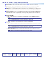
9. If necessary, wire a 2‑pole captive screw connector (provided) to your power supply as shown in gure 3.
Captive Screw Connector
Tie Wrap
Heat
Shrink
1/8"
(3 mm)
7/8"
(22 mm)
3/16"
(5 mm) Max.
Figure 3. Wiring the Power Connector
ATTENTION:
• The power supply must not be permanently xed to the building structure or similar structures.
• La source d’alimentation ne devra pas être xée de façon permanente à une structure de bâtiment ou à une
structure similaire.
• These power supplies are not suitable for use in air handling spaces or in wall cavities.
• Ces sources d’alimentation ne sont pas appropriées pour une utilisation dans les espaces d’aération ou dans les
cavités murales.
• Do not connect power to the switcher until you have read the CAUTION and ATTENTION notices on pages 5 and
6 of the SW HD 4K Series User Guide.
• Ne branchez pas l’alimentation au SW HD 4K Series avant d’avoir lu les mises en garde « CAUTION » et
«ATTENTION » aux pages 5 et 6.
10. Power on the output display.
11. Connect power to the switcher.
12. Power on the source devices.
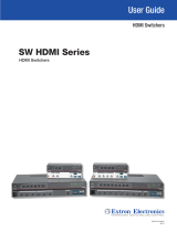
Front Panel Features
SW2 HD 4K
HDMI SWITCHER
1
IR
CONFIG
SIGNAL
INPUTS
INPUTS
OUTPUT
1 2
HDCP
2
AUTO
SWITCH
E
B CA D
F
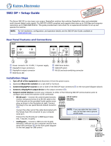
Figure 4. SW2 HD 4K Front Panel
SW4 HD 4K
HDMI SWITCHER
1
IR
CONFIG
SIGNAL
INPUTS
INPUTS
OUTPUT
1 2 3 4
HDCP
2 3 4
AUTO
SWITCH
F
B CA D E
Figure 5. SW4 HD 4K Front Panel
A
Auto Switch LED
B
IR receiver port
C
USB config port
D
Input selection
buttons
E
Input and Output
LEDs
F
HDCP LEDs
Product Category
3

Extron Headquarters
+1.800.633.9876 (Inside USA/Canada Only)
Extron USA - West Extron USA - East
+1.714.491.1500 +1.919.863.1794
+1.714.491.1517 FAX +1.919.863.1797 FAX
Extron Europe
+800.3987.6673
(Inside Europe Only)
+31.33.453.4040
+31.33.453.4050 FAX
Extron Asia
+65.6383.4400
+65.6383.4664 FAX
Extron Japan
+81.3.3511.7655
+81.3.3511.7656 FAX
Extron China
+86.21.3760.1568
+86.21.3760.1566 FAX
Extron Middle East
+971.4.299.1800
+971.4.299.1880 FAX
Extron Australia
+61.8.8351.2188
+61.8.8351.2511 FAX
Extron India
1800.3070.3777
Inside India Only
+91.80.3055.3777
+91.80.3055.3737 FAX
© 2016 Extron Electronics All rights reserved. www.extron.com
SW HD 4K Series • Setup Guide (Continued)
A
Auto switch LED — Lights when auto‑input switching is in effect (see step 6 on page 2 for more information).
B
IR receiver port — Detects infrared signals from the optional IR 102 remote control at a distance of up to 30 feet
(9.1 meters) and within 40 degrees off the axis (see the SW HD 4K Series User Guide for more information).
C
USB config port — Connect a USB cable (USB A to mini‑B) between your computer and this female USB mini‑B port
to congure and control the switcher via SIS commands or the Universal Switcher Control Program and to update the
rmware.
D
Input selection buttons — Press one of these buttons to select an input to switch to the output. The LED at the right
of each button lights when the corresponding input is selected. If auto‑input switching is in effect, these buttons are
disabled, but the LEDs continue to light to indicate the selected input. The input buttons are also used to initiate a
system reset and to enable and disable front panel lockout (see the SW HD 4K Series User Guide for more information).
E
Input and Output LEDs
• Input — Lights when a source is connected to the corresponding input connector and TMDS clock activity is
detected.
NOTE: If the source device connected to the selected input is HDCP encrypted (requires HDCP authentication),
the corresponding signal LED may not light unless HDCP has been authenticated.
• Output — Lights when an active sink (output) device is connected to the HDMI output.
F
HDCP LEDs
• Input — Lights if the connected sources are HDCP encrypted and has been authenticated by the switcher inputs.
NOTE: If the source device connected to the selected input is HDCP encrypted (requires HDCP authentication),
the corresponding signal LED may not light unless HDCP has been authenticated.
• Output — Lights when the currently selected input requires HDCP and the connected output device has been
successfully authenticated.
NOTE: HDCP is re‑authenticated on the output whenever a new input is selected.
68-2884-50 Rev. B
03 16
4
-
 1
1
-
 2
2
-
 3
3
-
 4
4


Extron electronics SW HD 4K Series User manual
- Type
- User manual
Ask a question and I''ll find the answer in the document
Finding information in a document is now easier with AI
in other languages
Related papers
-
 Extron electronics SW HD 4K PLUS Series User manual
-
 Extron electronics SW HDMI Series User manual
-
 Extron electronics SW HDMI Series User manual
-
 Extron electronics DTP T SW4 HD 4K User manual
-
 Extron electronics SW HD 4K PLUS Series User manual
-
 Extron electronics DTP2 T 204 User manual
-
 Extron electronics SW HDMI Series User manual
-
 Extron electronics SW2 DP User manual
-
Extron SW HDMI Series User manual
-
Extron electronics MPS 601 User manual


Other documents
-
-
Extron DTP T SW4 HD 4K User manual
-
-
-
Extron electronic RS-232 User manual
-
-
-
Extron DTP2 T 203 User manual
-
-