FFLED 120W INSTALLATION INSTRUCTIONS
Thank you for buying RAB lighting xtures. Our goal is to design the best quality products to get the job done right. We’d like to hear your comments.
Call the Marketing Department at 888-RAB-1000 or email: marketing@rabweb.com
®
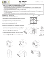
GUARD INSTALLATION
(ordered separately)
Wire Guard mount with (4) #10-24 Stainless Steel Screws.
Screws are provided with accessory. Line up guard with
existing, pre-drilled holes in frame as shown, tighten screws.
Guard, Shield and Hood may be used together.
Stainless Steel
Screws (4)
ACCESSORIES AND REPLACEMENT PARTS
(ordered separately)
Poly Shield: GDFFLED120P
Wire Guard: GDFFLED120W
5” Hood: HFFLED120-5 (Bronze)/
HFFLED120W-5 (White)
8” Hood: HFFLED120-8 (Bronze)/
HFFLED120W-8 (White)
Lens & Door Replacement: LFFLED120A (Bronze)/
LFFLED120W (White)
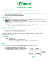
HOOD INSTALLATION
(ordered separately)
Hood mount with (4) #10-24 Stainless Steel Screws. Screws
are provided with accessory. Line up hood with existing,
pre-drilled holes in frame as shown, tighten screws. Guard,
Shield and Hood may be used together.
Stainless Steel
Screws (4)
GUARD/ SHIELD/ HOOD INSTALLATION
(ordered separately)
Wire Guard, Poly Shield and Hood can be mounted together
with (4) #10-24 Stainless Steel Screws. Screws are provided
with accessory. Line up shield, hood and guard with existing,
pre-drilled holes in frame as shown, tighten screws.
Stainless Steel
Screws (4)
POLY SHIELD INSTALLATION
(ordered separately)
Poly Shield mount with (4) #10-24 Stainless Steel Screws.
Screws are provided with accessory. Line up shield with
existing, pre-drilled holes in frame as shown, tighten screws.
Guard, Shield and Hood may be used together.
Stainless Steel
Screws (4)
RECEPTACLE OPTION
Units ordered with (/PCT) sux is supplied with 3 wire
receptacle and 120-277V Twistlock Photocell. Units ordered
with (/PCT4) is supplied with 3 wire receptacle and 480V
Twistlock Photocell.
Units ordered with (/7PR) sux is supplied with 7-Pin
receptacle without photocell. Brown and Orange wires from
the 7-Pin receptacle are not connected and are reserved to
DALI or other control systems.
Note: These instructions do not cover all details or variations in equipment nor do they provide for every possible situation during installation, operation
or maintenance.
Patent - US: Pat D643,147
Easy Answers
rabweb.com
Visit our website for product info
Tech Help Line
Call our experts - 888 722-1000
e-mail
Answered promptly - sales@rabweb.com
Free Lighting Layouts
Answered online or by request
© 2017 RAB LIGHTING Inc.
Northvale, New Jersey 07647 USA
FFLED120 IN 0917