Page is loading ...

`
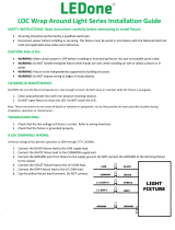
Installation Guide
SAFETY INSTRUCTIONS: Read instructions carefully before attempting to install fixture.
•All wiring should be performed by a qualified electrician.
•Disconnect power before installing or servicing. This fixture must be wired in accordance with the National Electrical
Code and applicable local codes and ordinances.
•Proper grounding is required to ensure personal safety.
CAUTION: Risk of fire
•WARNING: Make certain power is OFF before installing or maintaining fixture. No user serviceable parts inside.
•WARNING: Risk of shock when photoelectric switch is provided.
•WARNING: Please check if the voltage marked on the luminaire is consistent with the input voltage to be connected.
•WARNING: Do NOT use in an area with strong acid mist.
•WARNING: Make sure the installation position can withstand 10 times the weight of the luminaire before installing.
oInstall it at a flat place without vibration, swinging or fire hazards.
CLEANING & MAINTENANCE:
CAUTION: Be sure the fixture temperature is cool enough to touch. Do NOT clean or maintain while the fixture is energized.
1. Clean glass lens with non-abrasive glass cleaning solution.
2. Do NOT open fixture to clean the LED. Do NOT touch the LED.
Note: These instructions do not cover all details or variation in equipment, nor do they provide for every possible situation during
installation, operation or maintenance.
TROUBLESHOOT:
•If the light will not come on:
oA. Light switch is turned off. Turn light switch on.
oB. Fuse is blown, or circuit breaker is turned off. Replace fuse or turn circuit breaker on.
oC. Incorrect circuit wiring. Verify that fixture is wired properly.
WIRING:
Universal voltage driver permits operation at 277V through 480V, 50/60Hz. Follow wiring directions as in Fig. 1.
1. Connect the BLACK fixture lead to the (+) LINE supply lead.
2. Connect the WHITE fixture lead to the (-) COMMON supply lead.
3. Connect the GROUND wire from fixture to supply ground.

`
0-10V DIMMABLE WIRING:
Universal voltage driver permits operation at 277V through 480V, 50/60Hz. A 5-wire cord is provided. For 0-10V dimming, follow the
wiring instructions in Fig. 2.
1. Connect the BLACK fixture lead to the (+) LINE supply lead.
2. Connect the WHITE fixture lead to the (-) COMMON supply lead.
3. Connect the GROUND wire from fixture to supply ground. Do NOT connect the GROUND of the dimming fixture to
the output.
4. Connect the PURPLE fixture lead to the (V+) DIM lead.
5. Connect the GRAY fixture lead to the (V-) DIM lead.
6. Cap the YELLOW fixture lead, if present. Do NOT connect.
MOUNTING:
1. HOOK MOUNTING: Follow mounting directions as in Fig. 3 to 6
a. Fix the hook on the light. (clockwise rotation)
b. Use an electric drill to bore a hole in the wall.
c. Fix the hanger on the wall with screws.
d. Fix one end of the chain to the wall, another to the hook from the light and complete installation.

2. U-BRACKET MOUNTING: Follow mounting directions as in Fig. 7 to 10
a. Use an electric drill to bore 2 holes in the wall.
b. Set the expansion screws to the existing drilling holes.
c. Fix the u-bracket to the wall by nut, plain cushion and spring shim.
d. Use a wrench to reverse hexagon nut adjust the requested angle.
/