FläktGroup EQRA Rotary heat exchanger Installation and Maintenance Manual
- Type
- Installation and Maintenance Manual

Fläkt Woods 8652 GB 2011.02 1
Subject to alteration
Installation and maintenance instruction
EQRA Checks, Rotor Seals, Drive Unit
Rotary heat exchanger
Checks before starting the heat exchanger
– The fans must not be run during the construction
periodif the heat exchanger is not running.
– Also make sure that the appropriate filters have
been fitted.
– The rotor is free to rotate
– The peripheral seal of the rotor is in contact with
the partition, and that the gap is the same (approx.
8 mm) all round.
– The centre seal is lightly in contact with the rotor
allround.
– There is no significant damage to the rotor face.
– To prevent damage of the rotor surfaces, make
sure that no foreign objects have been left inside
the connected supply air and extract air ducts.
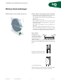
Rotor Seals
The EQRArotor
cassette is fitted with
sealing strips equipped
with synthetic bristles
with intervening
plastic foil. The sealing strips are fitted along the rotor
periphery and seal there against the inside of the facing
plate,
partially along the inside of the
dividing beam (Sizes 005 – 018)
or top (Sizes 023 –050).
The sealing strips are permanently mounted and under
normal circumstances do not require adjustment.

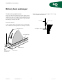
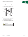
To adjust the peripheral seal
The rotor shaft is mounted in eccentric shaft moun-
tings.These can be turned individually to angle the shaft
and thus also the rotor in order to ensure that the sealing
gap is uniform all round. Adjustment to only one shaft-
mounting is normally sufficient.
Proceed as follows:
1.Back off the locknut and locking screw on the frontbe-
am of the shaft mounting which is mosteasily accessible.
Fläkt Woods 8652 GB 2011.02 2
Subject to alteration
Installation- instruction
2. When the gap is equal all round, tighten the locking
screw and refit the centre seal.
Rotary heat exchanger
Locking screws-
with locknuts
Front beam
Shaft mounting
Centre seal
Peripheral seal
Brush seal
Partition
Gap approx. 8 mm

Fläkt Woods 8652 GB 2011.02 3
Subject to alteration
Installation and maintenance instruction
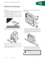
Drive Unit
The drive unit of the EQRA rotor cassette consists of a
motor base plate, drive motor with belt pulley for round
drive belt, motor base plate, and the necessary cables
and speed controller, if fitted.
Forall major service of thedriveunit or rotor,itisadvi-
sable to remove the entire motor base plate by backing
off the retaining screws, tilting the motor base plate as
shown and unhooking it up off the screws.
For the size 05 to 018 units, the motor is mounted on a
bracket with ”hooks” secured in recesses in the motor-
base plate. The bracket is secured by M6 screws.
For the size 018 to 050 and 054, 063, 072 units, the drive
motor is secured by screws directly to the motor base
plate.
After having correctly refitted and secured the motor,
fit the drive belt around the belt pulley. The drive belt
does not require re-tensioning.
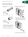
To Change the Rotor Bearings EQRA, Sizes
005 – 018
A. Withdraw the cassette from the Air Handling Unit
casing just so far that the rotor shaft retaining screw is
accessible. Remove the drive belt from the motor
pulley.Then dismantle the motor base plate, centre
spacer, rotation monitor and the speed controller
mounting bracket.
B. Blockuptherotorandbackofftheshaftretainingscrews.
Then dismantle one centre beam.Withdraw the rotor
shaft. Therotorcan now berolledout ofthe cassette.
Rotary heat exchanger
CAUTION!
Mark how the centre beam is mounted. If
it is not refitted correctly, the purging
sector will not purge the rotor passages!
A
B

Fläkt Woods 8652 GB 2011.02 4
Subject to alteration
Installation and maintenance instruction
C. The worn bearings can now be tapped out of the rotor
hub.
D. Clean the bearing positions and the inside of the
bearing casing to remove old grease and fit new
bearings. If you first chill the bearings, this will make
it easier to fit them. Use an intermediate ring in front
of the bearing to prevent bearing damage.
E. Roll the rotor back to its position inside the cassette
and refit the other components in the reverse order.
To Change the Rotor Bearings EQRA,
Sizes 020 – 050, 054, 063, 072
AA. Withdraw the cassette from the Air Handling Unit
casing just so far that the rotor shaft retaining screw
is accessible. Remove the drive belt from the motor
pulley. Then dismantle the stay, if fitted, the motor
base plate, centre spacer, rotation monitor and the
speed controller.
BB. Block up the rotor and remove the locking nuts and
lockingboltsoftheshaftmountasshowninfigure BB.
Rotary heat exchanger
C
D
Intermediate ring
BB
AA
To Change the Rotor Bearings EQRA,
Sizes 005 – 018

Fläkt Woods 8652 GB 2011.02 5
Subject to alteration
Installation and maintenance instruction
CC. Tap therotorshaftout of thehub without damaging
the shaft. Use a soft rod made of brass or the like!
Place the two spacer rings at a safe location and
clean them if necessary. These rings are seated
between the framework and the bearings.
DD. Then replace the bearings as described in Items C
and D in the previous section (sizes 005-018).
EE. Refit the details in the reverse order.
Rotary heat exchanger
CC
Locking bolt
Locking nut
IMPORTANT!
After you have fitted new bearings,
adjust the rotor as described on pages
6 and 7.
To Change the Rotor Bearings EQRA,
Sizes 020 – 050, 054, 063, 072

Fläkt Woods 8652 GB 2011.02 6
Subject to alteration
Installation and maintenance instruction
Shaft Adjustment EQRA, Sizes 020– 050
The rotor position is factory-preset and normally does
not need any adjustment.
However, adjustment may be necessary in certain
cases, for example after fitting new bearings. The rotor
position is simple to adjust provided that the recomm-
mended inspection sections have been arranged.
Otherwise, the cassette will have to be withdrawn out of
the AirHandling Unit.
A. Back off the locking nut and the lockingbolt.Adjust
the adjusting nuts to centre the shaft in the hole in
the centre support.
Do this on both sides of the frame.
Tighten the locking bolts applying a torque of 50 Nm.
The shaft is now in its initial position. Now check
that the rotor is correctly positioned.
If so, secure the locking bolt by means of the locking-
nut on both sides. If not, proceed with step ”B”.
B. Ascertain in which direction the rotor runs out.
Back off the locking bolts again. Use the adjustment
bolts to adjust the rotor to its proper position.
Tighten the locking bolts applying a torque of 50
Nm. Recheck the position of the rotor. If the rotor is
now centred, secure the locking bolt by tightening
the locking nut on both sides.
For an illustration of how to make this adjustment,
see figures beside.
Rotary heat exchanger
Locking nut Locking bolt
Adjusting bolt
Centre support
Vertical adjustment
Tighten the adjusting nuts in the same direction in rela-
tion to one another.
Tighten the adjusting nuts in opposite directions in
relation to one another.
Horizontal adjustment

Service schedule
Rotor - Face surfaces
Check that the rotor face is not coated with dust. Clean
by vacuum cleaning, or by blowing with compressed
air from the clean side towards the dust-coated side.
If vacuum cleaning or blowing with compressed air
proves insufficient for cleaning the rotor face (fatty
dust), proceed as follows:
Spray a grease solvent by hand, e.g. the degreasing
agent, on to the dust-coated rotor surface, and then
blow compressed air from the opposite side.
As an alternative, the rotor may be flushed with low-
pressure steam or water, provided that facilities are
available for collecting the water.
When cleaning by means of a high-pressure nozzle,
direct the jet at right angles so the rotor face structure.
The nozzle should preferably be held about 50 mm
from the rotor face. The pressure should not be higher
than 80 bar.
Bearings
The EQRA is equipped with permanently lubricated
bearings for which no maintenance is needed. Check
that the bearing sound is normal.
Purging sector
The EQRA has a permanently fitted purging sector.
Fläkt Woods 8652 GB 2011.02 7
Subject to alteration
Installation and maintenance instruction
Rotary heat exchanger
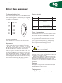
To change the drive belt
Due to wear, it may be necessary to change the drivebelt.
The original belt has a welded joint. The replacement
belt is jointed together by means of the pin supplied
with it. Make sure that the belt has the correct length
according to the table below.
Direction of rotation
Check that the rotor is rotating in the right direction.
Maintenance
Inspection and service on the heat recovery unit
concern mainly the rotor, seals and drive equipment.
The heat recovery unit is accessible for service
through the inspection doors which cover the whole of
the side wall. The rotor can be rolled out for service.
The intervals are based on the assumption that the
unit is in operation for about 2000 hours over a 12-
month period and operates in a normal comfort venti-
lation installation. If the dust content of the supply
and/or exhaust air is high, the unit should be inspec-
ted more frequently. Maintenance of the heat recovery
unit is greatly facilitated if the recommended equip-
ment is used for monitoring and purging operation.
Object Interval Action See page
Rotor face 6 months Inspect and clean,
if necessary. 7
Drive belt 6 months Check for tension 7
and wear.
Rotor bearings 12 months The EQRA has permanently 7
lubricated bearings.
Monitoring
equipment 12 months Check the performance.
N.B.
Never use methyl ethyl ketone, aceto-
ne or corrosive liquids.
Size Length, mm
005 1984
008 2932
011 3253
018 3863
023 4807
032 5084
041 5740
050 6688
072 7541
-
 1
1
-
 2
2
-
 3
3
-
 4
4
-
 5
5
-
 6
6
-
 7
7


FläktGroup EQRA Rotary heat exchanger Installation and Maintenance Manual
- Type
- Installation and Maintenance Manual
Ask a question and I''ll find the answer in the document
Finding information in a document is now easier with AI
Related papers
-
FläktGroup EQRO Rotary heat exchanger Installation and Maintenance Manual
-
-
-
-
-
-
-
-
-
Other documents
-
ABB MT series Installation And Maintenance Instruction
-
ABB AMG Series User manual
-
Datsun Saloon I300 Workshop Manual
-
-
 Solé Diesel MINI-23 User manual
-
 SSP M/103/0301 User manual
-
SPX Cooling Technologies MAG185-125 User manual
-
Toro Powerlite Snowthrower User manual
-
Woods TC/TCR74 User manual
-

