Page is loading ...

1 Functions FETA-19
1.1 Input Voltage Range
1.2 Inrush Current Limiting
1.3 Overcurrent Protection
1.4 Overvoltage Protection
1.5 Thermal Protection
1.6 Output Voltage Adjustment Range
1.7 Output Ripple and Ripple Noise
1.8 Remote ON/OFF
1.9 Isolation
1.10 Signal Output (LED / Warning / Alarm)
1.11 Sequence Diagram
2 Series/Parallel Operation FETA-23
3 Life Expectancy and Warranty FETA-24
FETA-19
FETA-19
FETA-19
FETA-19
FETA-20
FETA-20
FETA-20
FETA-20
FETA-21
FETA-21
FETA-22
2.1 Series Operation
2.2 Parallel Operation/Master-slave Operation
2.3 N+1 Parallel Redundancy Operation
4Others FETA-26
5Options FETA-27
4.1 Output Current Monitor
4.2 Auxiliary Power (AUX)
4.3 Output Capacitive Load Considerations
4.4 External Component (EMI/EMC Filter)
4.5 Ground
4.6 Variable Speed Fan
4.7 Conditions of the safety approval
5.1 Outline of Options
FETA-23
FETA-23
FETA-23
FETA-26
FETA-26
FETA-26
FETA-26
FETA-27
FETA-27
FETA-27
FETA-27
AC-DC Power Supplies Enclosed Type
Instruction Manual
FETA-18
June 25, 2020

1 Functions
¿ FETA2500BA, 3000BA
1.1 Input Voltage Range
¡Input voltage range of the power supplies is from AC170V to
AC264V.
¡In cases that conform with safety standard, input voltage range is
AC200-AC240V (50/60Hz).
¡If input value doesn’t fall within above range, a unit may not oper-
ate in accordance with specications and/or start hunting or fail.
If you need to apply a square waveform input voltage, which is
commonly used in UPS and inverters, please contact us.
¡When the input voltage changes suddenly, the output voltage ac-
curacy might exceed the specication. Please contact us.
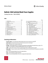
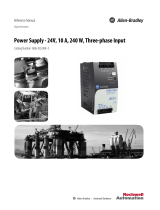
¿ FETA7000T
¡The input voltage range is AC170-264V (three-phase).
¡In cases that conform with safety standard, input voltage range is
AC200-AC240V (50/60Hz).
¡The input phase line shall not be specied, it can be connected to
any input terminal.
¡In the case of three-phase four-wire system, connect the three
wires to input terminal (L1, L2, L3), except ground wire.
AC170 - 264V
AC170 - 264V
Star connectionDelta connection
¡If the wrong input or single phase input is applied, the unit will not
operate properly and/or may be damaged. If you need to apply a
square waveform input voltage, which is commonly used in UPS
and inverters, please contact us.
¿ FETA7000ST
¡The input voltage range is AC300-480V (three phase four wire).
¡For the safety standard test, the input voltage range is AC346-
415V (three phase four wire, 50/60Hz).
¡The current owing through the neutral line (N phase) increases
when the AC input voltage is over AC456V three phase four wire
(18Amax). This does not affect product quality. Please select a
suitable wire gauge for the neutral line.
AC300 - 480V
Three phase four wire system
L1
L2 L3
N
¡Three phase three wire input voltage is not supported.
The neutral line must be connected.
If the input voltage is not from three phase four wire connection or
out of the specied range, the unit will not operate properly and/or
may be damaged. If you need to apply a square wave form input
voltage, which is commonly used in UPS and inverters, please
contact us.
1.2 Inrush Current Limiting
¡An inrush current limiting circuit is built-in.
¡If you need to use a switch on the input side, please select one
that can withstand an input inrush current.
¡Relay technique is used in the inrush current limiting circuit. When
you turn the power ON/OFF repeatedly within a short period of
time, please have enough intervals so that the inrush current limit-
ing circuit becomes operative.
¡When the switch of the input is turned on, the primary inrush cur-
rent and secondary inrush current will be generated because the
relay technique is used for the inrush current limiting circuit.
1.3 Overcurrent Protection
¡An overcurrent protection circuit is built-in and activated over
105% of the rated current. A unit automatically recovers when a
faulty condition is removed.
Please do not use a unit in short circuit and/or under an overcur-
rent condition.
¡Output voltage shuts down when the output voltage continuously
drops due to overcurrent protection.
¡Output voltage recovers from overcurrent protection by shutting
down the input voltage and waiting more than 10 seconds then
turning on AC input again, or turning off the output voltage by re-
mote control.
1.4 Overvoltage Protection
¡When output voltage is increased to the overvoltage protection
value, output voltage is shut down.
¡Output voltage recovers from overvoltage protection by shutting
down the input voltage and waiting more than 10 seconds then
turning on AC input again, or turning off the output voltage by re-
mote control.
Note :
¡Please avoid applying a voltage exceeding the rated voltage to an
output terminal. Doing so may cause a power supply to malfunc-
tion or fail. If you cannot avoid doing so, for example, if you need
to operate a motor, etc., please install an external diode on the
output terminal to protect the unit.
AC-DC Power Supplies Enclosed Type Instruction Manual
FETA-19 June 25, 2020

1.5 Thermal Protection
¡A thermal protection circuit is built-in.
The thermal protection circuit may be activated under following
conditions and shut down the output.
1
When a current and a temperature continue to exceed the val-
ues determined by the derating curve.
2
When a fan stops or air ow weakens by intake port or exhaust
port is blocked.
¡Output voltage recovers from thermal protection by shutting down
the input voltage and cooling down the inside of power supply ad-
equately then turning on AC input again, or turning off the output
voltage by remote control and cooling down the inside of power
supply adequately then turning on the output voltage by remote
control.
1.6 Output Voltage Adjustment Range
¡To increase an output voltage, turn the built-in potentiometer clock-
wise. To decrease the output voltage, turn it counterclockwise.
¡The power supplies have an external output voltage control func-
tion. The output voltage can be adjusted by changing the voltage
between the terminal TRM and the terminal COM on CN1/CN2.
You can decrease the voltage by drawing a current from the TRM
terminal.
You can calculate the output voltage in this case from formula 1
below.
Please do not apply +5V or more or negative voltage between
TRM and COM. Please contact us if you need accurate numbers.
Please do not apply negative Voltage to TRM terminal.
There is more than one method to adjust the output voltage, in-
cluding the methods to use external resistors and external power
supplies. Since each method has different characteristic, please
contact us for details.
Output voltage = Xrated output voltage--- 1
The voltage between
TRM and COM
2.5 [V]
If the output voltage decreases to 60% or less of rated voltage,
output ripple may increase.
Table 1.1 Output voltage adjustment range
Model Output voltage adjustment range [V]
FETA2500BA-36 approximately 0 to 39.6
FETA2500BA-48 approximately 0 to 52.8
FETA3000BA-48 approximately 15.0 to 52.8 *1
FETA7000T-48 approximately 0 to 52.8
FETA7000T-144 approximately0 to 158.4
FETA7000ST-48 approximately 0 to 52.8
FETA7000ST-144 approximately0 to 158.4
*1 The output voltage should not be adjusted to 15V or less be-
cause the ripple and ripple noise would be out of specs and the
unit would make the audible noise.
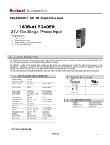
1.7 Output Ripple and Ripple Noise
¡Output ripple noise may be inuenced by measurement environ-
ment, measuring method Fig.1.1 is recommended.
+Vout
-Vout
Load
150mm
C
1
Oscilloscope
Bw:500MHz
Differential probe
+
C1 : Aluminum electrolytic capacitor 22μF
Fig.1.1 Measuring method of Ripple and Ripple Noise
Remarks :
When GND cable of probe with ux of magnetic force from power
supply are crossing, ripple and ripple noise might not measure
correctly.
Please note the measuring environment.
150mm
Bad example Good example
Fig.1.2. Example of measuring output ripple and ripple noise
1.8 Remote ON/OFF
¡These models have a remote ON/OFF function.
¡You can operate the remote ON/OFF function by sending signals
to CN1/CN2. Please see Table 1.2 and Table 1.3 for specifica-
tions and Fig.1.3 for connecting examples.
¡Please note the following when using the remote ON/OFF func-
tion.
1The output stops when a current ows to RC.
*
Reverse logic option (-R) is available for FETA 2500BA,
3000BA. Refer to section 5. Option.
2The current own to RC is a 20mA max.
3When the output voltage is turned off through the remote ON/OFF
circuit, the built-in fan slows down.
4If the output voltage is turned off through the remote ON/OFF
circuit, the WRN signals and the PG signals keep ”Low”.
5Description in this section is based on the assumption that you
will use one unit alone. If you are planning to use the units
in parallel operation or use multiple units for a single system,
please check necessary voltage and current values.
¡Please wire carefully. If done incorrectly, the internal components
of the unit may be damaged.
¡Remote ON/OFF circuits (RC and RCG) are isolated from input,
output, FG, AUX, WRN and PG.
AC-DC Power Supplies Enclosed Type Instruction Manual
FETA-20
June 25, 2020

Table 1.2 Specications of remote ON/OFF (RC-RCG)
Output voltage Between RC and RCG
ON L level (0 to 0.5V) or open
OFF H level (4.5 to 12.5V)
Table 1.3 Specications of remote ON/OFF (Case of Fig.1.3)
Connection method Fig.1.3 (a) Fig.1.3 (b) Fig.1.3 (c)
Power ON SW open
(0.1mA max)
SW close
(0.5V max)
Power OFF SW close
(3mA min)
SW open
(0.1mA max)
Base pin RCG AUXG RCG, AUXG
Ri=780WRi=780WRi=780W
RCG
RC RC RC
AUXAUX AUX
RCG
AUXG AUXG
RCG
AUXG
SW SW
SW
Rb=1kW
Vcc
Ra*1
(a)(b) (c)
12V
typ
12V
typ
12V
typ
Fig.1.3 Examples of connecting remote ON/OFF circuit
*1 If the output of an external power supply is within the range of
4.5 - 12.5V, you do not need a current limiting resistor Ra. If
the output exceeds 12.5V, however, please connect the current
limiting resistor Ra.
To calculate a current limiting resistance value, please use the
following equation.
Ra[W]= Vcc-(1.1+RiX0.005)
0.005
1.9 Isolation
¡When you run a Hi-Pot test as receiving inspection, gradually in-
crease the voltage to start. When you shut down, decrease the
voltage gradually by using a dial. Please avoid a Hi-Pot tester
with a timer because when the timer is turned ON or OFF, it may
generate a voltage a few times higher than the applied voltage.
1.10 Signal Output (LED/Warning/Alarm)
¡Functions of LED indicators and Output of Warning/Alarm are
shown below. LED indicators and Output of Warning/Alarm are
signals to check the presence/absence of voltage at the output
terminal of a power supply and to detect warning/fault conditions.
The timing of signals might be vary depending on input and load
conditions. Please evaluate thoroughly.
Table 1.4 Description of LED indicator
LED indicator Condition Output voltage
OFF Input power not present OFF
Green - ON Normal condition ON
Green - Blinking DC OFF by RC signal OFF
Amber - Blinking Warning condition
(refer to Table.2.5) ON
Amber - ON Fault condition
(refer to Table.2.6) OFF
Table 1.5 Description of the Warnings
Warning Output of Warning
WRN
The WRN signals are “Low”
when the power supply oper-
ates normally.
The signals turn “High” when
AC input voltage is out of
specification* or DC output
voltage is wrong (DC output
is out of voltage adjustment
range) or fan fan alarm/ter-
mal warning is detected.
Open collector method
Good : L level
( FETA2500BA,
FETA3000BA :
0 to 0.5V at 3mA
FETA7000T
FETA7000ST :
0 to 0.5V at 10mA)
Bad : H level or Open
(35Vmax)
* FETA7000ST
This does not affect product quality. The current owing through
the neutral line (N phase) increases when AC input voltage is over
AC456V three phase four wire (18Amax). Select a suitable wire
gauge for the neutral line.
AC-DC Power Supplies Enclosed Type Instruction Manual
FETA-21 June 25, 2020

Table 1.6 Description of the alarms (PG signal)
Alarm Output of Alarm
PG
The PG signals are ”Low”
when the power supply oper-
ates normally.
The signals turn ”High” when
the fan stops or the power
supply stops as a result of
output voltage decrease/stop,
activation of thermal protec-
tion, overvoltage protection,
overcurrent protection func-
tions or wrong input voltage
is applied.
Open collector method
Good : L level
( FETA2500BA,
FETA3000BA :
0 to 0.5V at 3mA
FETA7000T,
FETA7000ST :
0 to 0.5V at 10mA)
Bad : H level or Open
(35Vmax)
100kW0.1mF
PG / WRN
PGG / WRNG
Fig.1.4 Internal circuit of PG / WRN of FETA2500BA, 3000BA
100kW0.1mF
PG / WRN
PGG / WRNG
Fig.1.5 Internal circuit of PG / WRN of FETA7000T, 7000ST
¡Please note the followings when you use the warnings (WRN sig-
nal) and the alarms (PG signal).
1
The time it takes until the WRN signals and the PG signals turn
”High” vary depending on conditions.
2
If the output voltage is turned off through a remote ON/OFF cir-
cuit, the WRN signals and the PG signals keep ”Low”.
¡The WRN signal (Warning) circuit and the PG signal (Alarm) cir-
cuit are isolated from input, output, FG, RC and AUX.
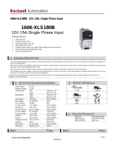
1.11 Sequence Diagram
(1)Turn ON/OFF by Remote ON/OFF control
: Indeterminate
ON
OFF
0V
0V
NG
OK
NG
OK
AUX
AC INPUT
Events
RC
PG
WRN
300ms max
500ms max
20ms min
10ms max
100ms min
10-100ms
RC
ON
RC
OFF
1700ms max
signal inhibit
time
Output
Voltage
AC
Input
AC
Loss
Fig.1.6 Sequence time chart by Remote ON/OFF control
(2)Turn ON/OFF by AC Input / Loss
: Indeterminate
ON
OFF
0V
0V
NG
OK
NG
OK
PG
WRN
AUX
AC INPUT
RC
10ms-10S
20ms min
100ms min
1700msmax
300msmax
500ms max
10-100ms
1ms min
Output
Voltage
Events
AC
Input
AC
Losss
Fig.1.7 Sequence time chart by AC Input / Loss
AC-DC Power Supplies Enclosed Type Instruction Manual
FETA-22
June 25, 2020

2 Series/Parallel
Operation
2.1 Series Operation
¡It is possible to connect multiple output voltages in series in order
to obtain higher output voltage. However, care should be taken as
follows:
Notes of (a) and (b) :
1 Please note that the maximum current available to the load is
equal to the current of the lowest rated supply in the string.
2 In case of malfunction (Failure or protection circuit activation),
please stop the operation and replace the failed power supply.
(c)
Load Load
Power
Supply
+
-
Power
Supply
+
-
Power
Supply
+
-
Remote ON/OFF
circuit (OFF signal)
(a)
Alarm signal
detect circuit
(b)
Power
Supply
+
-
Power
Supply
+
-
Power
Supply
+
-
Load Load
Remote ON/OFF
circuit (OFF signal)
Output voltage
monitor circuit
Fig.2.1 Examples of connecting in series operation
2.2 Parallel Operation/Master-slave Operation
¡You can use the power supplies in parallel operation by connect-
ing units as shown in Fig.2.2.
Please parallelly connect VB, CB and COM of each power supply
in parallel operation.
+V
VB
CB
COM
-V
Power supply Load
+V
VB
CB
COM
-V
Power supply
+V
VB
CB
COM
-V
Power supply
Fig.2.2 Example of parallel connection
¡Differences in the output current values among the power sup-
plies in parallel connection are 5% at most. Please make sure
that the sum of the output current values does not exceed a value
obtained from the following equation.
(Output current in parallel operation)
= (Rated current per unit) X (Number of unit) X0.95
¡When the number of units in parallel operation increases, the in-
put current also increases. Please design input circuitry (including
circuit pattern, wiring and current capacity for equipment) carefully.
¡Please make sure that the wiring impedance of a load from each
power supply becomes even. Otherwise, the output current bal-
ance circuit may become inoperative.
¡The maximum number of units in parallel operation for FETA-
2500BA, 3000BA are 10 and for FETA7000T, 7000ST are 3.
¡You can adjust the output voltage in parallel operation by adjusting
the potentiometer of just one power supply.
To do so, select one power supply as the master unit and turn the
potentiometers of the other (slave) power supplies clockwise to
the end.
Once you have done this, you can adjust the output voltage by
turning the potentiometer of the master unit.
¡Parallel connection with other products is not allowed.
2.3 N+1 Parallel Redundancy Operation
¡You can have N+1 redundancy operation for improved system reli-
ability.
¡N+1 redundancy operation is possible by connecting units as
shown in Fig.2.3.
VB, CB and COM are also connected together between all units
in parallel.
¡The output voltage gap of paralleled units must be adjusted within
+/-600mV for 144V type, and +/-200mV for the other output mod-
els.
¡Output current calculation is required based on following equation.
AC-DC Power Supplies Enclosed Type Instruction Manual
FETA-23 June 25, 2020

The current has to be more over normal operation current even if
one power supply fails.
Maximum output current [ Rated current per unit X Numbers of
normal operated units X 0.95
¡If you add one extra power supply in parallel operation, even if
one of the power supplies in your system fails, the remaining non-
failed power supplies continue to sustain the system. If one of the
power supplies stops operating, the output voltage may change
about 5%.
¡Parallel with other products is not allowed.
¡Please shut off the input voltage when you replace a failed power
supply.
¡After replacement, please make sure that all wirings are complet-
ed correctly, before re-applying input voltage.
¡Hot-swap or Hot-plug is not available.
¡2 or more power supplies failures may cause the output voltage to
decrease, lending the application system to shut down. Immediate
replacement is recommended when a power supply has failed.
+V
VB
CB
COM
-V
Power supply Load
+V
VB
CB
COM
-V
Power supply
+V
VB
CB
COM
-V
Power supply
Fig.2.3 Example of N+1 redundancy operating connection
¡If you have any questions about series, parallel and N+1 redun-
dancy operations, please contact us.
3 Life Expectancy and
Warranty
¿ FETA2500BA
¡Life Expectancy
Please see the following tables for life expectancy.
Table.3.1 Life Expectancy of FETA2500BA
Mounting Cooling
method
Average ambient
temperature
Life Expectancy
[years]
Io = 50% Io = 100%
All
direction
Forced air cooling
(internal fan)
Ta = 35C or less
6 5
Ta = 50C
4 3
Ta = 70C
2
-
*
This lifetime includes a built-in fan lifetime.
¡Life expectancy (R(t)=90%) of fan depends on use conditions as
shown in Fig.3.1.
Life expectancy of fan [H]
Ambient temperature[C]
4030 50 60 70 80
500,000
100,000
10,000 Io=50%
Io=100%
Fig.3.1 Life expectancy of fan of FETA2500BA
¡Warranty
Please see the following table for warranty. The warranty period
is 5 years maximum.
Table.3.2 Warranty
Mounting Cooling
method
Average ambient
temperature
Warranty [years]
Io = 50% Io = 100%
All
direction
Forced air cooling
(internal fan)
Ta = 35C or less
5 5
Ta = 50C
3 3
Ta = 70C
1
-
AC-DC Power Supplies Enclosed Type Instruction Manual
FETA-24
June 25, 2020

¿ FETA3000BA
¡Life Expectancy
Please see the following tables for life expectancy.
Table.3.3 Life Expectancy of FETA2500BA
Mounting Cooling
method
Average ambient
temperature
Life Expectancy
[years]
Io = 50% Io = 100%
All
direction
Forced air cooling
(internal fan)
Ta = 35C or less
6 4
Ta = 50C
4 3
Ta = 70C
1
-
*
This lifetime includes a built-in fan lifetime.
¡Life expectancy (R(t)=90%) of fan depends on use conditions as
shown in Fig.3.2.
Life expectancy of fan [H]
Ambient temperature[C]
3020 40 50 60 70
500,000
100,000
10,000 Io=50%
Io=100%
Fig.3.2 Life expectancy of fan of FETA3000BA
¡Warranty
Please see the following table for warranty. The warranty period
is 5 years maximum.
Table.3.4 Warranty
Mounting Cooling
method
Average ambient
temperature
Warranty [years]
Io = 50% Io = 100%
All
direction
Forced air cooling
(internal fan)
Ta = 35C or less
5 4
Ta = 50C
3 3
Ta = 70C
1
-
¿ FETA7000T
¡Life Expectancy
Please see the following tables for life expectancy.
Table.3.5 Life Expectancy of FETA7000T and FETA7000ST
Mounting Cooling
method
Average ambient
temperature
Life Expectancy
[years]
Io = 50% Io = 100%
All
direction
Forced air cooling
(internal fan)
Ta = 40C
7 5
Ta = 60C
4
-
*
This lifetime includes a built-in fan lifetime.
¡Life expectancy (R(t)=90%) of fan depends on use conditions as
shown in Fig 3.3.
Life expectancy of fan [H]
Ambient temperature[C]
3020 40 50 60 70
500,000
100,000
10,000 Io=50%
Io=100%
Fig.3.3 Life expectancy of fan of FETA7000T and FETA7000ST
¡Warranty
Warranty is 3 years.
AC-DC Power Supplies Enclosed Type Instruction Manual
FETA-25 June 25, 2020

4 Others
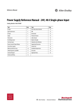
4.1 Output Current Monitor
¡You can monitor an output current by measuring a voltage be-
tween the terminal CB and COM.
¡Fig.4.1 shows the relationship between the voltage of the terminal
CB and the output current.
The output current shown in Fig.4.1 should be used only as a
guide.
Voltage of CB [V]
Load factor [%]
Load factor : Output current
Rated current
1
0
020406080 100
2
3
4
5
Fig.4.1 Load factor conversion graph
Note:
¡Careful wire connection is needed to avoid a malfunction caused
by noise.
¡Use a measuring instrument which has 500kW input impedance
or more.
¡Do not short between CB and COM because of possibility of fail-
ure.
4.2 Auxiliary Power (AUX)
¡The power supplies can generate an auxiliary power (AUX: 12V
0.15A) from CN1/CN2 to provide for remote ON/OFF and attached
circuits.
¡AUX circuit is isolated from other (input, output, FG, RC, WRN
and PG) circuits.
¡Please do not draw a current of 0.15A or higher from the auxiliary
power because doing so could damage the internal circuits or
cause malfunction.
When you connect a DC-DC converter, a current a few times
higher than normal current may ow at start-up. Please check the
current.
4.3 Output Capacitive Load Considerations
¡Please see Table 4.1 for maximum value of external output capac-
itance.If the external output capacitance exceeds the value shown
in Table 4.1, please contact us for details.
Table. 4.1 Maximum value of external output capacitance
Model Maximum value of external output
capacitance [μF]
FETA2500BA-36 22,000
FETA2500BA-48 22,000
FETA3000BA-48 22,000
FETA7000T-48 22,000
FETA7000T-144 7,500
FETA7000ST-48 22,000
FETA7000ST-144 7,500
4.4 External Component (EMI/EMC Filter)
¿ FETA2500BA, 3000BA, 7000T
FETA2500BA, FETA3000BA and FETA7000T can comply with
FCC Part 15 class B and CISPR32-B, EN55032-B, VCCI-B by
connecting an external EMI/EMC Filter.
Recommended EMI/EMC Filler :
FETA2500BA /3000BA: NAC-20-472 (COSEL)
FETA7000T : TAC-30-683 (COSEL)
¿ FETA7000ST
FETA7000ST can comply with FCC Part 15 class A and CIS-
PR32-A, EN55032-A, VCCI-A by connecting an external EMI/
EMC Filter.
Recommended EMI/EMC Filter:
FN3280H-25-32 (schaffner), B84131-M3-A116 (EPCOS) or
equivalent product.
L3
L2
L1
N
FG
EMI/EMC
FILTER
LOAD
300 - 480VAC
(3
f
4-Wire)
DC OUT +
DC OUT -
L3
L2
L1
N
FG
FETA7000ST
Fig.4.2 Connecting EMI/EMC Filter
AC-DC Power Supplies Enclosed Type Instruction Manual
FETA-26
June 25, 2020

4.5 Ground
¡When installing the power supply with your unit, ensure that the
input FG terminal is connected to safety ground of the unit.
4.6 Variable Speed Fan
¡The power supply has built-in variable speed cooling fan. The fan
speed is a function of load and ambient temperature.
4.7 Conditions of the safety approval
¡To apply for safety standard using this power supply, the following
conditions must be met.
1 This unit must be used as a component of the end-use equip-
ment.
2 This unit must be provided with overall enclosure.
3 The FG terminal must be connected to safety ground of the end-
use equipment, as required for class I equipment.
4 50A circuit breaker must be externally installed on the input side.
(FETA7000T, FETA7000ST)
5 Altitude of operation is up to 3,000 m.
5 Options
5.1 Outline of Options
*Please inquire for details of specications and delivery timing.
*
You can combine multiple options. Some options, however, can not
be combined with other options. Please contact us for details.
¿ -R (FETA2500BA, 3000BA)
¡Specication with reversed logic for remote ON/OFF operation.
Remote ON/OFF specification of Option-R is on Table 5.1 and
Table 5.2.
Table 5.1 Remote ON/OFF specication of Option-R (RC-RCG)
Output Voltage Between RC and RCG
OFF L level (0 to 0.5V) or Open
ON H level (4.5 to 12.5V)
Table 5.2
Remote ON/OFF specication of Option-R (Case of Fig.1.3)
Connection method Fig.1.3 (a) Fig.1.3 (b) Fig.1.3 (c)
Power OFF SW open
(0.1mA max)
SW close
(0.5V max)
Power ON SW close
(3mA min)
SW open
(0.1mA max)
Base pin RCG AUXG RCG, AUXG
¿ -F2 (FETA2500BA)
¡Specication with reversed air exhaust.
¡Differences from standard products are shown in Fig.5.1 and
Fig.5.2.
¡Fan operates at higher speed compare to standard product at low
ambient temperature.
¡Please contact us for details about life expectancy of fan.
(a) Front side(b) Rear side
Exhaust opening
Intake opening Air flow
Air flow
Fig.5.1 Location of intake port and exhaust port
80
7040 60-10210 30 5000
100
0
20
40
60
80
Load factor [%]
Ambient temperature [C]
Fig.5.2 Ambient temperature derating curve
AC-DC Power Supplies Enclosed Type Instruction Manual
FETA-27 June 25, 2020
/