Page is loading ...

Reference Manual
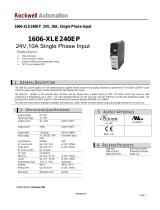
Power Supply Reference Manual - 24V, 40 A Single-phase Input
Catalog Number
1606-XLS960E
Topic Page Topic Page
AC Input 3 Front Side and User Elements 13
Input Inrush Current 4 EMC 14
DC Input 4 Environment 15
Output 5 Protection Features 16
Hold-up Time 7 Safety Features 16
DC-OK Relay Contact 7 Dielectric Strength 17
Shut-down Input 8 Standards and Certifications 17
Remote Control of Output Voltage 9 Approximate Dimensions 18
Internal Data Logging 9 Intended Use 18
Efficiency and Power Losses 10 Installation Requirements 18
Lifetime Expectancy and MTBF 11 Accessories 19
Functional Diagram 11 Application Notes 20
Terminal and Wiring 12

2 Rockwell Automation Publication 1606-RM052A-EN-P - August 2018
Power Supply Reference Manual - 24V, 40 A Single-phase Input
1606-XLS960E
24V, 40 A, Single-phase Input Power Supply
The Bulletin 1606-XLS DIN-rail power supplies are efficient and
small. Achieved by a synchronous rectification, a bridge-less PFC
circuit, and some additional unique design details.
Large power reserves of 150% and built-in large sized output capacitors
support the starting of heavy loads such as DC motors or capacitive
loads. The use of a unit from a lower wattage class can be used to save
space and cost.
High immunity to transients and power surges and low
electromagnetic emissions makes usage in nearly every environment
possible.
The integrated input fuse and the near zero input inrush current make
installation and usage simple. Diagnostics are easy due to the DC-OK
relay, a green DC-OK LED, and the red overload LED.
A large international approval package for various applications makes
this unit suitable for nearly every application.
• AC 100-240V Wide-range Input
• Width only 125 mm (4.9 in.), Weight only 1.9 kg (4.2 lb.)
• 94.6% Full Load and Excellent Partial Load Efficiencies
• 50% BonusPower®, 1440 W for up to 4 s
• 110 A High Peak Current for 10 ms for Easy Fuse Tripping
• Safe HiccupPLUS Overload Mode
• Active PFC (Power Factor Correction)
• Negligible Low Input Inrush Current Surge
• Full Power Between -25…+60 °C (-13…140 °F)
• Current Sharing Feature for Parallel Use
• Internal Data Logging for Troubleshooting Included.
• Remote Control of Output Voltage
• DC-OK Relay Contact
• Shut-down Input
• ATEX and IECEx Approved
Attribute Value
Output Voltage nom 24V DC nominal
Adjustment range 24 …28V DC
Output Current Continuous 40…34.3A
Short Term (4 seconds) 60…51.5A
Output Power Continuous 960 W
Short Term (4 seconds) 1440 W
Output Ripple, 20 Hz to 20 MHz < 100mVpp
Input Voltage, -15%/+10% 100…240V AC
Frequency, ± 6% 50…60 Hz
AC Inrush Current, at 120/230V AC 17/ 11 A peak
Efficiency at 120/230V AC 93.6/94.6%
Losses at 120/230V AC 65.6 / 54.8 W
Temperature, operating -25…+70°C
Derating 24 W / °C
+60…70°C
between 85…90V AC
Hold-up Time 27/27 ms
Dimensions W x H x D 125 x 124 x 127 mm
(4.9 x 4.88 x 5 in.)
Weight 1900 g /4.2 lb.

Rockwell Automation Publication 1606-RM052A-EN-P - August 2018 3
Power Supply Reference Manual - 24V, 40 A Single-phase Input
AC Input
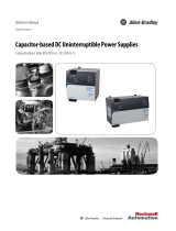
Figure 1 - Input Voltage Range
Figure 2 - Turn-on Behavior, Definitions
Figure 3 - Input Current vs. Output Load at 24V
Figure 4 - Power Factor vs. Output Load at 24V
Attribute Value Notes
AC input nom. 100…240V AC suitable for TN, TT, and IT mains networks
AC input range min 90…264V AC continuous operation
min 85…90V AC < 55 °C (131 °F) ambient temperature
continuously allowed
> 55 °C (131 °F) ambient temperature short
term or with output derating according to
Output Current vs. Ambient Temperature
on
page 15
min 60…85V AC full power for up to 200 ms
min 0…85V AC no damage to the unit
min 264…300VAC < 500 ms
Allowed
voltage L or N
to earth
max 300V AC continuous, IEC 62103
Input
frequency
nom. 50…60Hz ±6%
Tur n- on
voltage
typ 80V AC steady-state value, load-independent, see
Figure 1
Shut-down
voltage
typ 74V AC
External input
protection
See External Input Protection
on page 22.
Attribute 100V
AC
120V
AC
230V
AC
Notes
Input current typ 10.5 A 8.6 A 4.5 A at 24V, 40 A, see Figure 3
Power factor
(1)
(1) The power factor is the ratio of the true (or real) power to the apparent power in an AC circuit.
typ 0.99 0.99 0.99 at 24V, 40 A, see Figure 4
Crest factor
(2)
(2) The crest factor is the mathematical ratio of the peak value to RMS value of the input current waveform.
typ 1.47 1.53 1.56 at 24V, 40 A
Start-up delay typ 800 ms 750 ms 700 ms see Figure 2
Rise time typ 15 ms 15 ms 15 ms at 24V, 40 A, resistive
load, 0 mF see Figure 2
typ 18 ms 18 ms 18 ms at 24V, 40 A, resistive
load, 4 0mF see Figure 2
Tur n- on
overshoot
max 100 mV 100 mV 100 mV see Figure 2
Turn-on
85
Rated input range
V
IN
P
OUT
74 264V AC
Shut-down
80
Start-up
delay
Rise
Time
Overshoot
- 5%
Output
Voltage
Input
Voltage
40 A
4 8 12 16 20 24 28 32 36
0
2
4
6
8
10
12 A
Output Current
Input Current, typ.
A: 100V AC
B: 120V AC
C: 230V AC
A
B
C
Power Factor, typ.
4 8 12 16 20 24 28 32 36 40A
0.75
0.8
0.85
0.9
0.95
1.0
Output Current
A: 100V AC
B: 120V AC
C: 230V AC
A
B
C

4 Rockwell Automation Publication 1606-RM052A-EN-P - August 2018
Power Supply Reference Manual - 24V, 40 A Single-phase Input
Input Inrush Current
The power supply is equipped with an active inrush current limitation
circuit, which limits the input inrush current after turn-on to a
negligible low value. The input current is smaller than the steady state
input current.
Figure 5 - Typical Turn-on Behavior at Nominal Load and 25 °C (77 °F)
Ambient Temperature
DC Input
Do not operate this power supply with DC input voltage.
Attribute Value
(2)
100V AC 120V AC 230V AC
Inrush Current
(1)
Max 25 A 22 A 16 A
Typ 20 A 17 A 11 A
Inrush Energy Max 5 A
2
5 A
2
5 A
2
(1) The charging current into EMI suppression capacitors is disregarded in the first microseconds after switch-on.
(2) Over entire temperature range, mains interruptions >1 second.

Rockwell Automation Publication 1606-RM052A-EN-P - August 2018 5
Power Supply Reference Manual - 24V, 40 A Single-phase Input
Output
Attribute Value
Output nom 24V DC
Adjustment range min 24-28V DC guaranteed
max 29V DC
(1)
(1) BonusPower®, short-term power capability (up to typ 4 s) The power supply is designed to support loads with a higher short-term power requirement without damage or shutdown. The short-term duration is hardware that is
controlled by an output power manager. This BonusPower® is repeatedly available. If the power supply is loaded longer with the BonusPower® than shown in the Bonus-time diagram (See Figure 8 on page 6
), the max output
power is automatically reduced to 960 W. If the power requirement is continuously above 960 W and the voltage falls below approx. 20V (due to the current regulating mode at overload), the unit shuts-off and makes periodical
restart attempts. This behavior is called hiccup mode that is described below. If the voltage is above 20V, the unit continuously delivers current.
at clockwise end position of potentiometer
Factory setting typ 24.1V DC ±0.2%, at full load, cold unit, in “single use” mode
typ 24.1V DC ±0.5%, at full load, cold unit, in “parallel use” mode
typ 25.1V DC at no load, cold unit, in “parallel use” mode
Line regulation max 10 mV 85…300V AC
Load regulation max 50 mV in “single use” mode: static value, 0 A..40 A, see Figure 6 on page 6
typ 1000 mV in “parallel use” mode: static value, 0 A..40 A, see Figure 10 on page 7
Ripple and noise voltage max 100mVpp 20 Hz to 20 MHz, 50 Ohms
Output current nom 40 A continuously available at 24V, see Figure 6 and Figure 10 on page 7
nom 34.3 A continuously available at 28V, see Figure 6 and Figure 10 on page 7
nom 60 A short-term available BonusPower®, at 24V for typical 4 s, see Figure 6 and Figure 10 on
page 7
nom 51.5 A short-term available BonusPower®, at 28V for typical 4 s, see Figure 6 and Figure 10 on
page 7
typ 110 A up to 10 ms, output voltage stays above 20V, see Figure 8 on page 6, This peak current is
available once every second. See Peak Current Capability
on page 21 for more peak
current measurements.
Output power nom 960 W continuously available at 24-28V
nom 1440 W
(2)
(2) HiccupPLUS Mode Up to 4 s of overloading, the power supply delivers continuous output current. After this, the output power is reduced to nearly zero for approx. 17 s before a new start attempt is automatically performed. If the
overload has been cleared, the device will operate normally. If the overload still exists, the output current will be delivered for 2s to 4s (depending on the overload) again followed by a 17 s rest time. This cycle is repeated as long
as the overload exists. See Figure 7 on page 6
. During the off-period, a small rest voltage and rest current is present on the output.
short-term available BonusPower® at 24…28V
BonusPower® time typ 4 s duration until the output voltage dips, see Figure 8 on page 6
BonusPower® recovery time typ 7 s overload free time to reset power manager, see Figure 12 on page 7
Overload behavior cont. current output voltage > 20V DC, see Figure 6 on page 6
HiccupPLUS mode
(3)
(3) Discharge current of output capacitors is not included
output voltage < 20V DC, see Figure 6 on page 6
Short-circuit current min 60 A
(4)
(4) This is the maximum output voltage that can occur at the clockwise end position of the potentiometer due to tolerances. It is not guaranteed value that can be achieved. The typical value is about 28.5V.
load impedance 25mOhm, see Figure 7 on page 6
max 70 A load impedance 25mOhm, see Figure 7 on page 6
max 23 A average (R.M.S.) current, load impedance 25mOhm, see Figure 7 on page 6
typ 130 A up to 10 ms, load impedance <10mOhm, see Figure 11 on page 7
Output capacitance typ 10 200 μF included in the power supply

6 Rockwell Automation Publication 1606-RM052A-EN-P - August 2018
Power Supply Reference Manual - 24V, 40 A Single-phase Input
Figure 6 - Output Voltage vs. Output Current in “Single Use mode” typ
Figure 7 - Short-circuit on output, HiccupPLUS mode, typ
Figure 8 - Bonus time vs. output power
Figure 9 - BonusPower® after input turn-on
Output Voltage
0
010203040
4
8
12
28V
16
20
24
6050 70A
Output Current
Adjustment Range
A
B
A
B
Short-term (4s)
then switching
to curve
Continuously
available
A
Output
Current
0
65A
17s
17s
17s
2s
2s
2s
t
Short -circuit
Normal
operation
Normal
operation
ma
x
.
Bonus Time
0
100 120 130 140 150
170%
1
2
3
4
5s
110 160
Output Power
m
i
n
.
100%
Output
Voltage
Input
Voltage
Bonus
Power
Output
Power
150%

Rockwell Automation Publication 1606-RM052A-EN-P - August 2018 7
Power Supply Reference Manual - 24V, 40 A Single-phase Input
Figure 10 - Output voltage vs. output current in “parallel use” mode,
typ
Figure 11 - Dynamic overcurrent capability, typ
Figure 12 - BonusPower® recovery time
(1)
BonusPower® after output short
Hold-up Time
Figure 13 - Hold-up Time vs. Input Voltage
Figure 14 - Shut Down Behavior, Definitions
DC-OK Relay Contact
This feature monitors the output voltage produced by the power
supply. It is independent of a back-fed voltage from a unit that is
connected in parallel to the power supply output.
(1) The BonusPower is available as soon as power comes on and after the end of an output short circuit or
output overload.
Output Voltage
(Parallel Use, typ.)
22V
02040
23V
24V
25V
29V
26V
27V
28V
60A503010
Adjustment
Range
Factory
setting
Output Current
Continuously
allowed
Bonus
Power
Output Voltage
(dynamic behavior, < 10ms)
0
0
4
8
12
28V
16
20
24
150
A
6030 90 12015 45 75 105 135
Output Current
Adjustment
Range
Power
Demand
100%
t
t
Limitation by
Power Manager
Output
Voltage
Bonus Power disabled
Bonus
Time
Recovery Time
Short of
Output
100%
Output
Voltage
Bonus
Power
Output
Power
150%
100V AC 120V AC 230V AC
typ 54 ms 54 ms 54 ms at 24V, 20 A, see Figure 13
min 45 ms 45 ms 45 ms at 24V, 20 A, see Figure 13
typ 27 ms 27 ms 27 ms at 24V, 40 A, see Figure 13
min 23 ms 23 ms 23 ms at 24V, 40 A, see Figure 13
Attribute Value
Contact closes As soon as the output voltage reaches 90%
of the adjusted output voltage.
Contact opens As soon as the output voltage dips more
than 10% below the adjusted output
voltage. Short dips will be extended to a
signal length of 250 ms. Dips shorter than 1
ms will be ignored.
Contact recloses As soon as the output voltage exceeds 90%
of the adjusted voltage.
0
10 ms
20 ms
30 ms
40 ms
60 ms
90 120 155 190 230V AC
Input Voltage
50 ms
Hold-up Time
24V, 40 A, typ.
24V, 20 A, min.
24V, 20 A, typ.
24V, 40 A, min.
- 5%
Hold-up Time
Zero Transition
Output
Voltage
Input
Voltage

8 Rockwell Automation Publication 1606-RM052A-EN-P - August 2018
Power Supply Reference Manual - 24V, 40 A Single-phase Input
Figure 15 - DC-OK Relay Contact Behavior
Shut-down Input
This feature allows a switch-off of the output of the power supply with
a signal switch or an external voltage. The shut-down occurs
immediately while the turn-on is delayed up to 350 ms. In a shut-down
condition, the output voltage is <2V and the output power is <0.5 W.
The voltage between different minus pole output terminals must be
below 1V when units are connected in parallel. In a series operation of
multiple power supplies only wiring option “A” with individual signal
switches is allowed.
Figure 16 - Activation of the Shut-down Input
Contact ratings max 60V DC 0.3 A, 30V DC
1 A, 30V AC 0.5 A
resistive load
min 1 mA at 5V DC min permissible
load
Isolation voltage Refer to Dielectric Strength
on page 17
IMPORTANT Option C requires a current sink capability of the
voltage source. Do not use a blocking diode. -
The shut-down function has no safety feature
included.
Attribute Value
250ms
0.9* V
ADJ
<
1ms
10%
open
V
OUT
= V
ADJ
openclosed closed
>
1ms
15
16
OFF: linked
ON : open
Shut-
down
Input
Option A:
15
16
OFF: I > 0.3mA
ON : I < 0.1mA
Shut-
down
Input
Option B:
-
(via open
collector)
I
n.c.
15
16
OFF: U < 1V
ON : U = 4 -29V
Shut-
down
Input
Option C:
-
(via external
voltage
+
U
n.c.

Rockwell Automation Publication 1606-RM052A-EN-P - August 2018 9
Power Supply Reference Manual - 24V, 40 A Single-phase Input
Remote Control of Output Voltage
The shut-down input can also be used to remotely adjust the output voltage between typically 22V DC and 28V DC. All other functions of shut-
down input remain the same.
The control voltage is referenced to the main ground (negative output voltage)
Internal Data Logging
A protected microcontroller inside the power supply acquires and stores operating data during the life of the unit. The data can be downloaded with
a small tool and special software by the Rockwell Automation service and repair personnel, even when the unit is non-operational. The data allows
for better troubleshooting. Analysis of what happened before a failure can be determined much more accurately.
Acquired Data
• Family name of unit (1606-XLS), revision of firmware
• Operational hours
• Expired portion of lifetime (combination of temperature and time)
• Maximum ambient temperatures with timestamp (max 47 values)
• Maximal input voltages with timestamp (max 47 values) and type of input voltage (AC or DC)
• Failure report (various internal errors)
• Number and timestamp of input overvoltage transients
• Number and timestamp of over-temperature shut-downs
• Number of turn-on sequences
The data will be acquired with a fixed sampling rate unless the peak detectors do trigger due to an abnormal condition. In such cases, the abnormal
condition will be captured. Furthermore, data will be acquired every time shortly before the unit switches off.
Figure 17 - Remote Control of the Output Voltage Figure 18 - Applying the Control Voltage
Instructions
1. Set the unit into “Single Use” mode
2. Set the output voltage adjustment (24…28V) to the maximum desired voltage.
3. Apply a control voltage to reduce the output voltage
Output Voltage
12V
0V 5V
14V
16V
18V
28V
20V
22V
26V
Control Voltage
24V
10V
Potentiometer:
28V setting
24V setting
15
16
Control
Voltage
Shut-
down
Input
-
+
n.c.

10 Rockwell Automation Publication 1606-RM052A-EN-P - August 2018
Power Supply Reference Manual - 24V, 40 A Single-phase Input
Efficiency and Power Losses
Attribute 100V AC 120V AC 230V AC Notes
Efficiency, typ 93.2% 93.6% 94.6% at 24V, 40 A
Average efficiency, typ
(1)
(1) The average efficiency is an assumption for a typical application where the power supply is loaded with 25% of the nominal load for 25% of the time, 50% of the nominal load for another 25% of the time, 75% of the nominal load
for another 25% of the time and with 100% of the nominal load for the rest of the time.
92.7% 93.0% 93.9% 25% at 10 A, 25% at 20 A, 25% at 30 A. 25% at 40 A
Power losses, typ 3.6 W 3.5 W 3.3 W with activated shut-down
13.9 W 13.1 W 13.2 W at 24V, 0 A (no load)
36.1 W 34.5 W 30.6 W at 24V, 20 A (half load)
70.0 W 65.6 W 54.8 W at 24V, 40 A (full load)
Figure 19 - Efficiency vs. Output Current at 24V, typ Figure 21 - Power Losses vs. Output Current
Figure 20 - Efficiency vs. Input Voltage at 24V, 40 A, typ Figure 22 - Power Loses vs. Input Voltage at 24V, 40 A. typ
Efciency
8 1216202428323640 A
88
89
90
91
92
93
Output Current
94
95
96%
1
2
0
V AC
1
0
0
V AC
230V AC
Power Losses
0 4 8 1216202428 40 A
10
0
30
40
50
70
80 W
120V AV
100V AC
230V AC
32 36
60
20
Output Current
Efciency
85 120
155
190 225 260V AC
89
90
91
92
Input Voltage
93
94
95%
Power Losses
20
30
40
50
60
70
80W
85 120
155
190 225 260V AC
Input Voltage

Rockwell Automation Publication 1606-RM052A-EN-P - August 2018 11
Power Supply Reference Manual - 24V, 40 A Single-phase Input
Lifetime Expectancy and MTBF
Functional Diagram
Figure 23 - Functional Diagram
Attribute AC 100V AC 120V AC 230V Notes
Calculated lifetime expectancy
(1)
(1) The calculated lifetime expectancy that is shown in the table indicates the minimum operating hours (service life) and is determined by the lifetime expectancy of the built-in electrolytic capacitors. Lifetime expectancy is
specified in operational hours and is calculated according to the capacitor’s manufacturer specification. The manufacturer of the electrolytic capacitors only guarantees a maximum life of up to 15 years (131 400 h). Any number
exceeding this value is a calculated theoretical lifetime that can be used to compare devices.
288 000 h 291 000 h 317 000 h at 24V, 20 A and 25 °C (77 °F)
102 000 h 103 000 h 112 000 h at 24V, 20 A and 40 °C (104 °F)
163 000 h 181 000 h 238 000 h at 24V, 40 A and 25 °C (77 °F)
57 000 h 64 000 h 84 000 h at 24V, 40 A and 40 °C (104 °F)
MTBF
(2)
(2) MTBF represents Mean Time Between Failure, which is calculated according to statistical device failures, and indicates reliability of a device. It is the statistical representation of the likelihood of a unit to fail and does not
necessarily represent the life of a product. The MTBF figure is a statistical representation of the likelihood of a device to fail. A MTBF figure of, for example, 1 000 000h means that statistically one unit will fail every 100 hours if 10
000 units are installed in the field. However, it cannot be determined if the failed unit has been running for 50 000h or only for 100 h.
SN 29500, IEC 61709 491 000 h 481 000 h 537 000 h at 24V, 40 A and 25 °C (77 °F)
274 000 h 269 000 h 300 000 h at 24V, 40 A and 40 °C (104 °F)
MIL HDBK 217F Ground
Benign
170 000 h 171 000 h 183 000 h at 24V, 40 A and 25 °C (77 °F);
Ground Benign GB25
126 000 h 127 000 h 137 000 h at 24V, 40 A and 40 °C (104 °F);
Ground Benign GB40
MIL HDBK 217F Ground Fixed 36 000 h 36 000 h 39 000 h at 24V, 40 A and 25 °C(77 °F);
Ground Fixed GF25
27 000 h 27 000 h 30 000 h at 24V, 40 A and 40 °C (104 °F);
Ground Fixed GF40
+
+
-
-
V
OUT
DC-ok
Contact
Output
Over-
Voltage
Protection
Bridgeless
PFC
Converter
Input Fuse
Input Filter
Inrush Limiter
Output
Voltage
Regulator
Power
Converter
Output
Filter
DC ok
Relay
Output
Voltage
Monitor
Output
Power
Manager
Temper-
ature
Shut-
down
Overload
LED
DC-ok
LED
N
L
Single /
Parallel
Shut-down
Input &
Remote
Control
Shut-
down
13
14
15
16
Event Datalogger

12 Rockwell Automation Publication 1606-RM052A-EN-P - August 2018
Power Supply Reference Manual - 24V, 40 A Single-phase Input
Terminal and Wiring
The terminals are IP20 Finger safe constructed and suitable for field and factory wiring.
Daisy Chaining
Daisy chaining (jumping from one power supply output to the next) is allowed as long as the average output current through one terminal pin does
not exceed 54 A. If the current is higher, use a separate distribution terminal block as shown inFigure 25.
Type Input Output DC-OK, Shut-down
screw termination screw termination spring-clamp termination
Solid wire 0.5-6mm2 0.5…16 mm2 0.15-1.5mm2
Stranded wire 0.5-4mm2 0.5…10 mm2 0.15-1.5mm2
American Wire Gauge AWG 20-10 AWG 22-8 AWG 26-14
max wire diameter 2.8 mm (including ferrules) 5.2 mm (including ferrules) 1.5 mm (including ferrules)
Wire stripping length 7 mm (0.28 in.) 12 mm / 0. 5 inch 7 mm / 0.28 inch
Screwdriver 3.5 mm slotted or cross-head No 2 3.5 mm or 5 mm slotted or cross-head No 2 3 mm slotted (to open the spring)
Recommended tightening torque 1 Nm, 9 lb.in 2.3 Nm, 20.5 lb.in Not applicable
• Use appropriate copper cables that are designed for minimum operating temperatures of: 60 °C for ambient up to 45 °C and 75 °C for ambient up to 60 °C minimum 90 °C for
ambient up to 70 °C minimum.
• Follow national and local installation codes and installation regulations.
• Ensure that all strands of a stranded wire enter the terminal connection.
• Do not use the unit without PE connection.
• Unused terminal compartments should be securely tightened.
• Ferrules are allowed.
Figure 24 - Daisy Chaining of Outputs Figure 25 - Using Distribution Terminals
Load
+
-
Power
Supply
+ +
- -
Output
Power
Supply
+ +
- -
Output
max 54 A
Distribution
Terminals
Load
+
-
Power
Supply
+ +
- -
Output
Power
Supply
+ +
- -
Output

Rockwell Automation Publication 1606-RM052A-EN-P - August 2018 13
Power Supply Reference Manual - 24V, 40 A Single-phase Input
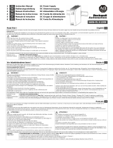
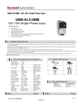
Front Side and User Elements
1.Input Terminals
(Screw terminals) N, L Line input ...PE (Protective Earth) input
2.Output Terminals
(Screw terminals, two pins per pole) + Positive output – Negative (return) output
3.“Parallel Use” “Single Use”
Selector Set jumper to “Parallel Use” when power supplies are connected in parallel to
increase the output power. To achieve a sharing of the load current between the
individual power supplies, the “parallel use” regulates the output voltage in such a
manner that the voltage at no load is approx. 4% higher than at nominal load. A missing
jumper is equal to a “Single Use” mode.
4.Output Voltage
Potentiometer Multi turn potentiometer; Open the flap to set the output voltage.
Factory set: 24.1V at full output current, “Single Use” mode.
5.DC-OK LED (green)
On, when the voltage on the output terminals is >90% of the adjusted output voltage
6.Overload LED (red)
On, when the voltage on the output terminals is <90% of the adjusted output voltage, or
if there is a short circuit in the output. - Flashing, when the shut-down has been
activated or the unit has switched off due to over-temperature. - Input voltage is
required
7.DC-OK Relay Contact
The DC-OK relay contact is synchronized with the DC-OK LED.Refer to DC-OK
Relay Contact on page 7.
8.Shut-down and Remote Control Input
Allows the power supply to be shut down. Can be activated with a switch contact or an
external voltage. The remote control input allows adjusting the output voltage between
22V and 28V. Refer to Shut-down Input
on page 8 and Remote Control of Output
Vo l t a g e on page 9.
Status Indicators
Status Indicator Overload Status Indicator DC-OK Status Indicator DC-OK Contact
Normal mode OFF ON Closed
During BonusPower® OFF ON Closed
Overload (Hiccup mode) flashing OFF Open
Output short circuit flashing OFF Open
Temperature Shut-down flashing OFF Open
Active Shut-down input flashing OFF Open
No input power OFF OFF Open
DC 24V / 40A
+
+
Allen-Bradley
DC ok
OVL
24-
28V
Shut-
Down
Parallel Use
Single Use
13
14
16
15
DC ok
POWER SUPPLY
1606-XLS
1606-XLS960E
18WM
IND.CONT.EQ.
QUALITY
N
L
Input
AC 100-240V
M
N
O
P
Q
R
S
T

14 Rockwell Automation Publication 1606-RM052A-EN-P - August 2018
Power Supply Reference Manual - 24V, 40 A Single-phase Input
EMC
EMC Immunity According to generic standards: EN 61000-6-1 and EN 61000-6-2
The 1606-XLS960E is suitable for applications in industrial environment and in residential, commercial, and light industry environment without any restrictions.
Electrostatic discharge EN 61000-4-2
contact discharge 8 kV Criterion A
air discharge 15 kV Criterion A
Electromagnetic RF field EN 61000-4-3 80MHz-2.7GHz 20V/m Criterion A
Fast transients (Burst) EN 61000-4-4
input lines 4 kV Criterion A
output lines 2 kV Criterion A
signal lines (coupling clamp) 2 kV Criterion A
Surge voltage on input EN 61000-4-5
L .. N 2 kV Criterion A
L .. PE, N .. PE 4 kV Criterion A
Surge voltage on output EN 61000-4-5
+ .. - 1 kV Criterion A
+ / - .. PE 1 kV Criterion A
Surge voltage on signal lines
EN 61000-4-5 DC-OK signal.. PE 1 kV Criterion A
EN 61000-4-5 Shut-down input.. PE not relevant due to wire length
(1)
(1) Do not use wires longer than 30 m for the shut-down or input or use an additional protection.
Conducted disturbance EN 61000-4-6 0.15-80MHz 20V Criterion A
Line voltage dips EN 61000-4-11
0% of 100V AC 0V AC, 20 ms Criterion A
40% of 100V AC 40V AC, 200 ms Criterion C
70% of 100V AC 70V AC, 500 ms Criterion A
0% of 200V AC 0V AC, 20 ms Criterion A
40% of 200V AC 80V AC, 200 ms Criterion A
70% of 200V AC 140V AC, 500 ms Criterion A
Voltage interruptions EN 61000-4-11 0% of 200V AC (=0V) 5000 ms Criterion C
Voltage sags SEMI F47 0706
dips on the input voltage according to SEMI F47 standard
80% of 120V AC (96V AC) 1000 ms Criterion A
70% of 120V AC (84V AC) 500 ms Criterion A
50% of 120V AC (60V AC) 200 ms Criterion A
Powerful transients VDE 0160 over entire load range 750V, 1.3 ms Criterion B
(2)
(2) Criterion A is fulfilled for output up to 30 A.
Criterion Description
A Power supply shows normal operation behavior within the defined limits.
B Output voltage will dip from 24V to 21V for 5 ms
C Temporary loss of function is possible. Power supply can shut-down and restarts by itself. No damage or hazards for the power supply will occur.
EMC Emissions According to generic standards: EN61000-6-3 and EN61000-6-4
Conducted emissions input line EN 55011, EN 55022, FCC Part 15, CISPR 11, CISPR 22 Class B
Conducted emission output lines IEC/CISPR 16-1-2, IEC/CISPR 16-2-1 10 dB higher than average limits for DC power port according to EN 61000-6-3
(1)
(1) Tested with constant current loads, non pulsing
Radiated emission EN 55011, EN 55022 Class B
Harmonic input current EN 61000-3-2 Fulfilled for Class A equipment
Voltage Fluctuations, flicker EN 61000-3-3 Fulfilled
(2)
(2) Restrictions apply for applications in residential, commercial, and light-industrial environments, where local DC power networks according to EN 61000-6-3 are involved. No restrictions for all kinds of industrial applications.
This device complies with FCC part 15 rules
Operation is subjected to following conditions: (1) this device cannot cause harmful interference, and (2) this device must accept any interference received, including interference that can cause
undesired operation.

Rockwell Automation Publication 1606-RM052A-EN-P - August 2018 15
Power Supply Reference Manual - 24V, 40 A Single-phase Input
Switching Frequencies
Environment
Switching Frequencies The power supply has four converters with four different switching frequencies included. One is nearly constant. The others are
input voltage and load dependent.
Switching frequency 1 105 kHz Resonant converter, nearly constant
Switching frequency 2 1…150 kHz Boost converter, input voltage, and load dependent
Switching frequency 3 1…100 kHz PFC converter, input voltage, and load dependent
Switching frequency 4 25…45 kHz Aux. converter, input voltage, and load dependent
Attribute Value Notes
Operational temperature
(1)
(1) Operational temperature is the same as ambient or surrounding temperature and is defined as the air temperature 2 cm below the unit.
-25…+70 °C (-13… +158 °F) reduce output power according to Figure 26
Storage temperature -40 …+85°C (-40…+185 °F) for storage and transportation
Output de-rating 24 W/°C 60…70°C (140…158 °F)
Humidity
(2)
(2) Do not energize when condensation is present.
5 … 95% r.H. IEC 60068-2-30
Vibration sinusoidal 2…17.8 Hz: ±1.6 mm; 17.8…500 Hz: 1 g
(3)
2 hours / axis
(3) Higher levels that are allowed when using wall mounting bracket.
IEC 60068-2-6
Shock 15 g 6 ms, 10 g 11 ms
(4)
3 bumps / direction, 18 bumps in total
(4) Higher levels that are allowed when using wall mounting bracket.
IEC 60068-2-27
Altitude 0 … 2000 m (0 … 6 560 ft) without any restrictions
2000…6000 m (6560…20 000 ft) reduce output power or ambient temperature, see
Figure 27
IEC 62103, EN 50178, overvoltage category II
Altitude de-rating 60 W/1000 m or 5°C/1000 m > 2000 m (6500 ft), see Figure 27.
Over-voltage category III IEC 62103, EN 50178, altitudes up to 2000 m
II altitudes 2000...6000 m
Degree of pollution 2 IEC 62103, EN 50178, not conductive
LABS compatibility The unit does not release any silicone or other LABS-critical substances and is suitable for use in paint shops.
Figure 26 - Output Current vs. Ambient Temperature Figure 27 - Output Current vs. Altitude
Allowed Output Current at 24V
0
-25 0 20 40
70°C
10
20
30
40
50
60A
60
Ambient Temperature
A
B
A
.
.
.
9
0
-
2
6
4
V
AC
B
.
.
.
8
5
-
9
0
V
AC
c
o
n
t
i
n
u
o
u
s
f
o
r
t
y
p
.
4
s
Allowed Output
Current at 24V
0
0 2000 4000
6000 m
10
20
30
40
50
60A
c
o
n
t
i
n
u
o
u
s
Altitude
f
o
r
t
y
p
.
4
s
A
...
T
a
m
b
<
6
0
°
C
B
.
.
.
T
a
m
b
<
5
0
°
C
C
.
.
.
T
a
m
b
<
4
0
°
C
A
B
C

16 Rockwell Automation Publication 1606-RM052A-EN-P - August 2018
Power Supply Reference Manual - 24V, 40 A Single-phase Input
Protection Features
Safety Features
Feature Description
Output protection Electronically protected against overload, no-load, and short-circuits
(1)
(1) In case of protection event, audible noise can occur.
Output over-voltage protection typ 30V DC max 32V DC In case of an internal power supply defect, a redundant circuit limits the
maximum output voltage. The output shuts down and automatically
attempts to restart.
Degree of protection IP 20 EN/IEC 60529 Caution: For use in a controlled environment according to
CSA 22.2 No 107.1-01.
Penetration protection > 5 mm for example, screws, small parts
Over-temperature protection yes Output shut-down with automatic restart
Input transient protection MOV (Metal Oxide Varistor)
Internal input fuse included not user replaceable
Attribute Value/Description
Input / output separation
(1)
(1) Double or reinforced insulation
SELV IEC/EN 60950-1
PELV IEC/EN 60204-1, EN 50178, IEC 62103, IEC 60364-4-41
double or reinforced insulation
Class of protection I PE (Protective Earth) connection required
Isolation resistance > 5MOhm input to output, 500V DC
PE resistance < 0.1 Ohms
Touch current (leakage current) typ 0.39 mA / 1.0 mA 100V AC, 50 Hz, TN-,TT-mains / IT-mains
typ 0.56 mA / 1.43 mA 120V AC, 60 Hz, TN-,TT-mains / IT-mains
typ 0.90 mA / 2.25 mA 230V AC, 50 Hz, TN-,TT-mains / IT-mains
max 0.50 mA / 1.21 mA 110V AC, 50 Hz, TN-,TT-mains / IT-mains
max 0.71 mA / 1.73 mA 132V AC, 60 Hz, TN-,TT-mains / IT-mains
max 1.18 mA / 2.82 mA 264V AC, 50 Hz, TN-,TT-mains / IT-mains

Rockwell Automation Publication 1606-RM052A-EN-P - August 2018 17
Power Supply Reference Manual - 24V, 40 A Single-phase Input
Dielectric Strength
The output voltage is floating and has no ohmic connection to the ground. Type and factory tests are conducted by the manufacturer. Field tests
may be conducted in the field using the appropriate test equipment that applies the voltage with a slow ramp (2 s up and 2 s down). Connect all
input-terminals together and all output poles before conducting the test. When testing, set the cut-off current settings to the value in the table
below.
Figure 28 - Dielectric Strength
To fulfill the PELV requirements according to EN60204-1 § 6.4.1, we recommend
that either the + pole, the – pole or any other part of the output circuit shall be
connected to the protective earth system. This helps to avoid situations in which a
load starts unexpectedly or cannot be switched off when unnoticed earth faults occur.
Standards and Certifications
Attribute A B C D
Type test 60 s 2500V AC 3000V AC 500V AC 500V AC
Factory test 5 s 2500V AC 2500V AC 500V AC 500V AC
Field test 5 s 2000V AC 2000V AC 500V AC 500V AC
Cut-off current setting > 20 mA > 20 mA > 40 mA > 1 mA
EC Declaration of Conformity The CE mark indicates conformance with the - EMC directive 2014/30/EU ,
Low-voltage directive (LVD) 2014/35/EU
RoHS directive 2011/65/EU.
UL 508 Listed for use as Industrial Control Equipment; U.S.A. (UL 508) and Canada (C22.2 No. 107-1);
E-File: E56639
UL 60950-1 Recognized for use as Information Technology Equipment, Level 5;
U.S.A. (UL 60950-1) and Canada (C22.2 No. 60950-1); E-File: E168663.
Applicable for altitudes up to 2000 m.
ANSI / ISA 12.12.01-Class I Div 2 Certified for use in Hazardous Location Class I Div 2 T4 Groups A,B,C,D systems;
U.S.A. (ANSI / ISA 12.12.01) and Canada (C22.2 No. 213)
EN 60079-0, EN 60079-15 Approval for use in hazardous locations Zone 2 Category 3G. Number of ATEX certificate: EPS 14 ATEX 1 638 X The power
supply must be built in in an IP54 enclosure.
IEC 60079-0, IEC 60079-15 Suitable for use in Class 1 Zone 2 Groups IIa, IIb and IIc locations.
Number of IECEx certificate: IECEx EPS 14.0081X
A
D
C
B
B
*
L
Input DC-ok
13
14
Earth, PE
Output
15/16
+/-
Shut-down
N
* When testing input to DC-OK ensure that the max. voltage between DC-OK and the output
is not exceeded (column D). We recommend connecting DC-OK pins and the output pins
together when performing the test.

18 Rockwell Automation Publication 1606-RM052A-EN-P - August 2018
Power Supply Reference Manual - 24V, 40 A Single-phase Input
Approximate Dimensions
Intended Use
• This device is designed for installation in an enclosure and is intended for the general use such as in industrial control, office,
communication, and instrumentation equipment.
• Do not use this power supply in equipment, where malfunction may cause severe personal injury or threaten human life.
• This device is designed for use in hazardous, non-hazardous, ordinary, or unclassified locations.
Installation Requirements
• This device may only be installed and put into operation by qualified personnel.
• This device does not contain serviceable parts. The tripping of an internal fuse is caused by an internal defect.
• If damage or malfunction should occur during installation or operation, immediately turn power off and send unit to the factory for
inspection.
• Mount the unit on a DIN-rail so that the output and input terminals are on the bottom of the unit. For other mounting orientations see de-
rating requirements in this document. Refer to Mounting Orientations
on page 26.
• This device is designed for convection cooling and does not require an external fan. Do not obstruct airflow and do not cover ventilation
grid (for example, cable conduits) by more than 15%.
• Keep the following installation clearances: 40 mm on top, 20 mm on the bottom, 5 mm on the left and right sides are recommended when
the device is loaded permanently with more than 50% of the rated power. Increase this clearance to 15 mm in case the adjacent device is a
heat source (for example, another power supply).
• A disconnecting means shall be provided for the output of the power supplies when used in applications according to
CSA C22.2 No 107.1-01.
Attribute Value/Description
Weight 1900 g (4.2 lb)
Din-Rail Use 35mm DIN-rails according to EN 60715 or EN 50022 with a height of 7.5 or 15 mm. The DIN-rail height must be added to the unit depth (127 mm) to calculate the total
required installation depth.
Installation Clearance See Installation Requirements
.
Figure 29 - Front View Figure 30 - Side View

Rockwell Automation Publication 1606-RM052A-EN-P - August 2018 19
Power Supply Reference Manual - 24V, 40 A Single-phase Input
Accessories
Wall Mounting Bracket - Catalog Number 1606-XLC
Buffer Module
This buffer unit is a supplementary device for DC 24V power supplies. It delivers
power to bridge typical mains failures or extends the hold-up time after turn-off of the
AC power. In times when the power supply provides sufficient voltages, the buffer
unit stores energy in integrated electrolytic capacitors. In case of mains voltage fault,
this energy is released again in a regulated process. One buffer module can deliver 20
A. To buffer the full output current of 40 A, two buffer modules are needed in
parallel.
The buffer unit does not require any control wiring. It can be added in parallel to the load circuit at any given point. Buffer units can be added in
parallel to increase the output ampacity or the hold-up time.
WARNING: Risk of electrical shock, fire, personal injury, or death.
– Do not use the power supply without proper grounding (Protective Earth).
– Use the terminal on the input block for earth connection and not one of the screws on the housing.
– Turn power off before working on the device. Protect against inadvertent repowering.
– Make sure that the wiring is correct by following all local and national codes.
– Do not modify or repair the unit.
– Do not open the unit as high voltages are present inside.
– Use caution to prevent any foreign objects from entering the housing.
– Do not use in wet locations or in areas where moisture or condensation can be expected.
– Do not touch during power-on, and immediately after power-off. Hot surfaces may cause burns.
WARNING: Notes for use in hazardous location areas:
– The power supply is suitable for use in Class I Division 2 Groups A, B, C, D locations and for use in Group II Category 3 (Zone 2) environments and are evaluated
according to EN 60079-0:2012 and EN 60079-15:2010.
WARNING: WARNING EXPLOSION HAZARDS
– Substitution of components may impair suitability for this environment. Do not disconnect the unit or operate the voltage adjustment or S/P jumper unless
power has been switched off or the area is known to be non-hazardous.
– A suitable enclosure must be provided for the end product that has a minimum protection of IP54 and fulfils the requirements of the EN 60079-15:2010.
DC
AC
+
-

20 Rockwell Automation Publication 1606-RM052A-EN-P - August 2018
Power Supply Reference Manual - 24V, 40 A Single-phase Input
Redundancy Module
The cat. no. 1606-XLSRED80HE is equipped with two input channels (40 A each), which are individually decoupled by utilizing mosfet
technology. The output current can go as high as 80 A. Using mosfets instead of diodes reduces the heat generation and the voltage drop between
input and output. The 1606-XLSRED80HE does not require an additional auxiliary voltage and is self-powered even if there is a short circuit
across the output.
Due to the low-power losses, the unit is slender and only requires 46 mm width on the DIN-rail.
Redundancy Module
The 1606-XLSREDS40HE is a 40 A single channel redundancy module, which is equipped with a plug connector on the output. The plug
connector allows replacing the power supply or the redundancy module while the system is running. The plug connector avoids that the output
wires can touch and short the load circuit.
The1606-XLSREDS40HE is slender and only requires 46 mm width on the DIN-rail. It also utilizes mosfet technology instead of diodes for low
heat generation and a minimal voltage drop between input and output. It does not require an additional auxiliary voltage and is self-powered even if
there is a short circuit across the output
Application Notes
Repetitive Pulse Loading
Typically, a load current is not constant and varies over time. This power supply is designed to support loads with a higher short-term power demand
(=BonusPower®). The short-term duration is hardware that is controlled by an output power manager and is available on a repeated basis. If the
BonusPower® load lasts longer than the hardware controller allows it, the output voltage will dip and the next BonusPower® is available after the
BonusPower® recovery time has elapsed.
To avoid this, the following rules must be met:
• The power demand of the pulse must be below 150% of the nominal output power.
• The duration of the pulse power must be shorter than the allowed BonusPower® time. (see output section)
• The average (R.M.S.) output current must be below the specified continuous output current. If the R.M.S. current is higher, the unit will
respond with a thermal shut-down after a period of time. Use the maximum duty cycle curve (Figure 34 on page 21
) to check if the average
output current is below the nominal current.
• The duty cycle must be below 0.75.
Figure 31 - Typical 1+1 Redundant configuration for 40 A
with a dual redundancy module
Figure 32 - Typical N+1 or 1+1 Redundant configuration for 40 A with
multiple redundancy modules
Redundancy
Module
+
-
+
-
Input
1
Input
2
Output
L N PE
+ +
- -
24V, 40A
Parallel Use
Single Use
DC-
OK
24-28V 960W
Power Supply
AC Input
L N PE
+ +
- -
24V, 40A
Parallel Use
Single Use
DC-
OK
24-28V 960W
Power Supply
AC Input
24V
40A
Load
Failure
Monitor
L
N
PE
I
I
L N PE
+ +
- -
24V, 40A
Parallel Use
Single Use
DC-
OK
24-28V 960W
Power Supply
AC Input
L N PE
+ +
- -
24V, 40A
Parallel Use
Single Use
DC-
OK
24-28V 960W
Power Supply
AC Input
Redundancy
Module
+
-
Input
Output
+
-
Redundancy
Module
+
-
Input
Output
+
-
L
N
PE
I
I
24V
40A
Load
Failure
Monitor
/