Page is loading ...

MAX-6MAX-6
*1 Input current is based on Modul M1F-HFEC-00 (MAX1600F : 5V80A, 12V34A, 15V27A, 24V17A) outputs 1500W at AC100V.
*2 M1T
-HFEC-00 (MAX1600T : 5V80A, 12V34A, 15V27A, 24V17A) outputs 1600W at AC200V.
*3 M3T
-HHFFEECC-00 (MAX3200T : 5V80A X 2, 12V34A X 2, 15V27AX 2, 24V17AX 2) outputs 3200W at AC200V.
The value changes by composing the output modules.
Model Circit method PCB/Pattern
Material
Single sided Double sided
Series/Parallel
operation availability
Series operation
Parallel operation
Switching frequency
[kHz]
Input current
[A]
Rated input
fuse
Active filter 65 FR-4 Yes
-
Forward converter 370
--
FR-4 Yes Yes
19
6.5
Input module of
MAX1600F
Output module
250V 50A
Inrush current
protection
-
SCR
Yes
-
Rectifilter and filter
-
FR-4 Yes
-
Input module of
MAX1600T
250V 15A SCR
-
13Rectifilter and filter
-
FR-4 Yes
-
Input module of
MAX3200T
250V 30A SCR
-
Basic Characteristics Data
*1
*2
*3
Basic Characteristics Data

MAX-7MAX-7
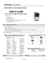
EFFECIENCY (M1F-HFEC-00)
Load factor100%
Load factor 50%
INPUT VOLTAGE [V]
100 140 180 220 260 30060
70.0
72.0
74.0
76.0
78.0
80.0
82.0
84.0
EFFECIENCY [%]
POWER FACTOR & INPUT CURRENT (M1F-HFEC-00)
Load factor100%
Load factor 50%
INPUT VOLTAGE [V]
POWER FACTOR
100 140 180 220 260 300
INPUT CURRENT [A]
0
5
10
15
20
25
30
1.0
0.5
60
0.6
0.7
0.8
0.9
INPUT CURRENT
POWER FACTOR
Load factor 100%
HARMONIC ORDER
HARMONIC CURRENT [A]
0
10
0.001
0.01
0.1
1
10 20 30 40
Harmonic current standard class A (at odd number)
Input voltage AC230V
INPUT HARMONIC CURRENT AC230V (M1F-HFEC-00)INPUT HARMONIC CURRENT AC100V (M1F-HFEC-00)
HARMONIC ORDER
HARMONIC CURRENT [A]
0304
0
0.001
0.01
0.1
1
10
10 20
Input voltage AC100V
Harmonic current standard class A (at odd number)
Load factor 100%
INRUSH CURRENT (M1F-HFEC-00)
100ms/DIV
20A/DIV
Frequency 60Hz
Load factor 100%
Input voltage AC100V
INSTANTANEOUS INTERRUPTION COMPENSATION (M1F-CCCC-00 )
OUTPUT POWER [W]
0
INSTANTANEOUS COMPENSATION TIME [ms]
INPUT VOLTAGE 100V
400 800 1200 16000
20
40
60
80
100
OVER CURRENT CHARACTERISTICS (M1F-HFEC-00)
OUTPUT CURRENT [A]
0
5.0
10.0
15.0
20.0
25.0
20.0 40.0 60.0 80.0 100.0
OUTPUT VOLTAGE [V]
24V
15V
12V
5V
RISE TIME & FALL TIME (M1F-HFEC-00)
ACIN 100V
=
Io
100%
10ms/DIV
+
AC Input
+
DC Output
100ms/DIV
24V
+ 15V
+ 12V
5V
MAX1600F

MAX-8MAX-8
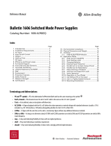
EFFECIENCY (M1T-CCCC-00)
Load factor 100%
Load factor 50%
INPUT VOLTAGE [V]
140 160 180 200 220 240 260 280120
EFFECIENCY [%]
70
72
74
76
78
80
82
84
86
POWER FACTOR & INPUT CURRENT (M1T-CCCC-00)
Load factor 100%
Load factor 50%
INPUT VOLTAGE [V]
POWER FACTOR
140 160 180 200 220 240 260 280
INPUT CURRENT [A]
1.0
0.5
120
0.6
0.7
0.8
0.9
INPUT CURRENT
POWER FACTOR
0
2.5
5.0
7.5
10.0
INRUSH CURRENT (M1T-CCCC-00)
20A/DIV
Frequency 60Hz
Load factor 100%
Input voltage AC200V
50ms/DIV
INSTANTANEOUS INTERRUPTION COMPENSATION (M1T-CCCC-00)
OUTPUT POWER [W]
INSTANTANEOUS COMPENSATION [ms]
INPUT VOLTAGE 200V
0 400 800 1200 1600
20
40
60
80
100
24V
15V
12V
5V
OUTPUT CURRENT [A]
0
5.0
10.0
15.0
20.0
25.0
20 40 60 80 100
OUTPUT VOLTAGE [V]
OVER CURRENT CHARACTERISTICS (M1T-HFEC-00)
ACIN 200V
=Io 100
%
10ms/DIV
+
AC Input
+
DC Output
100ms/DIV
24V
+ 15V
+12V
5V
RISE TIME & FALL TIME (M1T-HFEC-00)
MAX1600T

MAX-9MAX-9
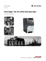
EFFECIENCY (M3T-CCCCCCCC-00)
Load factor 100%
Load factor 50%
INPUT VOLTAGE [V]
140 160 180 200 220 240 260 280120
EFFECIENCY [%]
70
72
74
76
78
80
82
84
86
POWER FACTOR & INPUT CURRENT (M3T-CCCCCCCC-00)
Load factor 100%
Load factor 50%
INPUT VOLTAGE [V]
POWER FACTOR
140 160 180 200 220 240 260 280
INPUT CURRENT [A]
1.0
0.5
120
0.6
0.7
0.8
0.9
INPUT CURRENT
POWER FACTOR
0
5.0
10.0
15.0
25.0
20.0
INRUSH CURRENT (M3T-CCCCCCCC-00)
20A/DIV
Frequency 60Hz
Load factor 100%
Input voltage AC200V
50ms/DIV
INSTANTANEOUS INTERRUPTION COMPENSATION (M3T-CCCCCCCC-00)
OUTPUT POWER [W]
INSTANTANEOUS COMPENSATION [ms]
INPUT VOLTAGE 200V
0
40
20
80
60
120
140
160
100
800400 1200 1600 2000 2400 2800 3200 3600
24V
15V
12V
5V
OUTPUT CURRENT [A]
0
5.0
10.0
15.0
20.0
25.0
20 40 60 80 100
OUTPUT VOLTAGE [V]
OVER CURRENT CHARACTERISTICS (M3T-HHFFEECC-00)
ACIN 200V
=Io 100
%
10ms/DIV
+
AC Input
+
DC Output
100ms/DIV
24V
+ 15V
+12V
5V
RISE TIME & FALL TIME (M3T-HHFFEECC-00)
MAX3200T


MAX-11MAX-11
AC-DC Power Supplies Congurable Type
2 Function MAX-13
2.1 Input voltage range MAX-13
2.2 Inrush current limiting MAX-13
2.3 Overcurrent protection MAX-13
2.4 Overvoltage protection MAX-13
2.5 Thermal protection MAX-13
2.6 External output voltage adjustment MAX-14
2.7 Remote ON/OFF MAX-14
2.8 Remote sensing MAX-14
2.9 Isolation MAX-15
2.10 Alarm MAX-15
Instruction Manual
4.1 Installation method MAX-16
4.2 Derating MAX-17
4Assembling and installation method MAX-16
1Ordering information MAX-12
3.1 Series operation MAX-15
3.2 Parallel operation/Master-slave operation MAX-16
3Series operation and Parallel operation MAX-15

MAX-12
1 Ordering information
M
M1F:MAX1600F
M1
T:MAX1600T
M
3T:MAX3200T
8
7
6
5
4
1
MAX1600F
MAX1600T
MAX3200T
Option
Series code
(Blank if not required.)
codecode
1
4 2
3
5
6
7
8
Series bar Shorted bar
Parallel code
(”00” if parallel
operation is not
required.)
slot
slot
Choose from Table 1.2.
(MAX1600F/MAX1600T)
Choose from Table 1.3.
(MAX3200T)
3 2
(Lower voltage to highter voltage.
If module is not required, set”O” for
the slot.)
Table 1.1 Output module code
Code A B C D E F G H I O
Output voltage [V]
2 3.3 5 7.5 12 15 18 24 28
Blank
panel
Output current [A]
80 80 80 54 34 27 22 17 14.5
Output power [W]
160 264 400 405 408 405 396 408 406
Table 1.2 Parallel / Series code
slot4 slot3slot2slot1
00
01
02
03
04
05
06
07
Code
: Output terminal
: Connection
Table 1.3 Parallel / Series code
: Output terminal
: Connection
0
1
2
3
4
5
6
7
Code”a”
slot8
Code”b”
0
1
2
3
4
5
6
7
8
9
A
B
C
D
E
F
slot7 slot6 slot5 slot4 slot3 slot2 slot1
¿Conguration rules
(1) After the output voltage and the output current are confirmed,
the code of the output module installed in the slot1-8 is selected
from Table 1.1.
Put the blank panel(code O) in when modules are not installes in
the slots.
(2) When output module is operated in parallel and series, the paral-
lel code can be selected from Table 1.2 and Table 1.3 depending
on whether or not the bus bar between the output modules ex-
ists.
(3) Do not put the blank panel in the slot1 because fan alarm and
open phase alarm* (ALM signal) is output from CN1 of the slot1.
MAX1600T/MAX3200T
(4) Do not put the blank panel in between the output modules con-
nected in parallel.
(5) Install more than two output modules in the slot.
(MAX1600F/MAX1600T)
Install more than four output modules in the slot. (MAX3200T)
(6) Modules with low output voltage should be installed out of the
slot1 in order.
MAX-12
AC-DC Power Supplies Congurable Type
Instruction Manual

MAX-13
¿Example of naming
M3T
OH
CCC
10C
03
Optional (C:PCB is coated)
F-module available in serial connection
at �15V 27A, or 30V 27A slot6 to slot5
are series connected with the shorted
bar.
The series code”a” of slot6-5 is
obtained”1” and the series code”b” of no
connected obtained”0” according to table
1.3.
C-module available in parallel
connection at 5V 216A slot3 to slot1 are
series connected with the shorted bar.
The series code”a” of no connected
obtained”0” and the series code”b” of
slot3-1 is obtained”3” according to table
1.3.
D-module 7.5V 54A
H-module 24V 17A
Blank panel
Unit MAX3200T
”a”
code
”b” ”a”
code
”b”
DFF
▪
The total output current in parallel is shown output module speci-
cations.
▪
If the wrong input or single phase input is applied, the unit will not
operate properly and/or may be damaged. Avoid the followings to
cause failure of the unit to apply square waveform input voltage,
which is commonly used in UPS and inverters.
2.2 Inrush current limiting
▪Inrush current limiting is built-in.
▪
If a switch on the input side is installed, it has to be the one han-
dling the input inrush current.
▪The thyristor technique is used for protection from inrush current.
When power is turned ON/OFF repeatedly within a short period
of time, it is necessary to have enough time between power ON
and OFF to operate circuit for inrush current.
When the switch of the input is turned on, the primary inrush cur-
rent and secondary inrush current are generated.
2.3 Overcurrent protection
▪
Overcurrent protection is built-in and comes into effect over 105%
of the rated current.
Overcurrent protection prevents the unit from short circuit and
overcurrent condition.
The unit automatically recovers when the fault condition is
cleared.
▪
If the output voltage drops more than 50% of the rated voltage in
an overcurrent protection mode, the average current will also be
reduced by the hiccup operation.
2.4 Overvoltage protection
▪Overvoltage protection circuit is built-in and comes into effect 115
- 140% of the rated voltage(except 3.3V output voltage type : it
operates at 4.0 - 5.5V).
The AC input should be shut down if overvoltage protection is op-
eration.
The minimum interval of AC recycling for recovery is more than 3
minutes.
The recovery time varies depending on input voltage.
2.5 Thermal protection
▪
Thermal protection circuit is built-in and avoid the followings to
shut down at operating thermal protection.
·
When the current and the temperature which deviates from the
derating characteristic are consecutive.
·
The case FAN stops or the case the wind out of FAN is inter-
rupted and the amount of the wind decreases.
After the input voltage is intercepted and the inside of the power
supply cools enough, the return after the overheating protection
operates turns on the input of the power supply again.
2.1 Input voltage range
¿MAX1600F
▪The range is from AC85V to AC264V or from DC120V to DC350V.
▪
In cases that conform with safety standard, input voltage range is
AC100-AC240V(50/60Hz).
▪
If the wrong input is applied, the unit will not operate properly and/
or may be damaged. Avoid the followings to cause failure of the
unit to apply square waveform input voltage, which is commonly
used in UPS and inverters.
¿MAX1600T/MAX3200T
▪The input voltage range is AC170-264V(three-phase).
Units are not inuenced by the phase sequence.
The voltage line of the three-phase is connected, and the earthing
conductor cannot be used for the three-phase four line type.
AC170 - 264V
AC170 - 264V
Star connectionDelta connection
▪
In cases that conform with safety standard, input voltage range is
AC200-AC240V(50/60Hz).
2 Function
MAX-13
AC-DC Power Supplies Congurable Type
Instruction Manual

MAX-14
2.6 External output voltage adjustment
▪
By applying the voltage externally or connecting register exter-
nally between TRM and -S, output voltage becomes adjustable.
Output level is able to be calculated by following equation1 ;
however, external output voltage should not be less than -0.7V
and more than 2.5V.
Rated output voltage ①
The voltage between
TRM and -S
Output voltage = 1 [V]
2.7 Remote ON/OFF
▪
Each output module has remote ON/OFF. ON/OFF of output
voltage becomes available. Table 2.1 shows the specication of
remote ON/OFF.
Fig.2.1 shows the way to connect remote control(Example), and
followings are notes when you use the remote control.
1
The output stops when the current is drown in RC3. The current
drowning RC3 is less than 12mA.
2
Built-in fans do not stop even if the output is turned off with re-
mote ON/OFF circuit.
3
The IOG signal is output when the output voltage is turned off with
remote ON/OFF.
4
You should be careful of electric potential in series when you wire
the remote control circuit,since it is not insulated from the output.
Example of a circuit in series is shown in Fig.2.2.
▪
It is possible turn on and turn off by the remote control of the mas-
ter module, because RC2 of the output module is connected with
RC3 in the power supply in parallel operation.
However, please note that currents necessary for the control
increase more than the time used with the output module unit be-
cause RC2 and RC3 of the output module are connected in parallel.
OFF
AUX
RC3
RC2
2.2KΩ
150Ω
12V
typ POWER
ON
-S
CN1
(a)
AUX
RC3
RC2
2.2KΩ
150Ω
12V
typ
POWER
ON
-S
CN1
OFF
(b)
ON
AUX
RC3
RC2
2.2KΩ
150Ω
12V
typ POWER
OFF
-S
CN1
(c)
Fig.2.1 Examples of connecting remote ON/OFF of output module
Table 2.1 Specication of remote ON/OFF
Connection method Fig.2.10(a) Fig.2.10(b) Fig.2.10(c)
SW Logic
Output on SW open
(0.1mA max)
SW open
(0.1mA max)
SW close
(0.5V max)
Output off SW close
(3mA min)
SW close
(3mA min)
SW open
(0.1mA max)
pin - -S -S
TRM
+V
+S
-S -V
CB
VB
RC2
RC3
RC2
-S
Output
model Load
TRM
+V
+S
-S -V
CB
VB
RC2
RC3
RC2
-S
Output
model
Fig.2.2 Example of remote control circuit in series operation
2.8 Remote sensing
▪
Remote sensing circuit is built-in each output module.
▪ Wiring method without using remote sensing is shown in Fig.2.3.
When you do not use the remote sensing, connect between +S
and +M and between -S and -M with CN1 of each output module.
When the power supply is shipped out of a factory, a special har-
ness is mounted on CN1 of the output module.
Load
Short at connector
+M
+S
-S
-M
+V
-V
OUT
Output module
CN1
Fig.2.3 When not using remote sensing function
MAX-14
AC-DC Power Supplies Congurable Type
Instruction Manual

MAX-15
2.10 Alarm
▪
Table 2.2 shows the alarm function built-in the power supply.
Table 2.2 Explanation of alarms
Alarm Output of alarm
ALM
When the fan stops or the power
supply breaks down (or one of
three phase is open), the alarm
from CN1 of the output module
of slot1.
Open collector method
Good : Low(0.5Vmax at 5mA)
Bad : High or open
35V 10mA max
TMP
When the thermal protection
circuit of the output module oper-
ates immediately or before, the
alarm outputs.
Good : High(5V typ)
Bad : Low(0.5Vmax at 5mA)
35V 10mA max
IOG
When the switching operation in
the output module stops.
Good : Low(0.5Vmax at 5mA)
Bad : High(5V typ)
35V 10mA max
MAX1600T / MAX3200T
▪
Notes, you should be careful of electric potential in series when
you wire the alarm circuit, since it is not isolated from the output.
ALM
-S
TMP
or
IOG
-S
22kΩ
6Vtyp
100kΩ 0.1uF
Fig.2.5 Internal circuit of ALM Fig.2.6 Internal circuit of TMP and IOG
3.1 Series operation
▪
Series operation is possible between the output modules in the
same power supply as shown below. Output current in series con-
nection should be lower than the lowest rated current in each unit.
Output
module
Output
module
Output
module
Output
module
Load
Load
Load
Fig.3.1 Connection method in series
▪
Output current in series connection is the same as the specica-
tion of the connected module.
▪
Please notice and set the following items.
1Choosing same modules in series setting in principle.
2
The rating voltage of the total in series setting can set less
than 48V.
3
It is impossible to use series setting with parallel setting.
Please consult us excluding the above-mentioned.
▪Wiring method with remote sensing is shown in Fig.2.4.
▪Notes, when you use the remote sensing, are shown as follows.
1
Note connecting wires enough because the load current ows to
sensing line and an internal circuit of power supply is damaged
occasionally, when defective contact of the screw such as loosen-
ing happens in the load line.
2
Conform the line drop should be at 0.3V or less using a thick wire
from the power supply to the load.
3
When remote sensing function is used, output voltage might be-
come unstable because of a impedance of wiring and load condi-
tion. And the power supply should be evaluated enough.Following
are examples to improve it.
·
-S sensing wire is removed and terminals between -M and -S are
shorted.
· C0 and R1 are connected as above gure.
Please ask details to us.
▪
When using remote sensing in parallel, you use remote sensing
out of a module that should be a master module and other output
module in parallel should be open between ±S and ±M.
▪Do not take out the output current of ±M at CN1.
Wire +S and -S as close as possible
Load
+
C0
+M
+S
-S
-M
+V
-V
OUT
Output module
R1
CN1
Fig.2.4 When using remote sensing function
2.9 Isolation
▪
For a receiving inspection, such as Hi-Pot test, gradually increase
(decrease) the voltage for start(shut down). Avoid using Hi-Pot
tester with the timer because it may generate voltage a few times
higher than the applied voltage, at ON/OFF of a timer.
If the unit is tested on the isolation between input & output and
output & FG must be shorted all output.
3 Series operation and
Parallel operation
MAX-15
AC-DC Power Supplies Congurable Type
Instruction Manual

MAX-16
3.2 Parallel operation/Master-slave operation
▪
Parallel operation is possible between the output modules in the
same power supply.(Already set up at the time of shipping out.
Impossible for user to set up.)
The output terminal of the module(set up for parallel operation)
should be connected with a shorted bar.
Do not apply input voltage after you remove the shorted bar be-
cause it can be damaged. The connection in parallel is shown in
Fig.3.2.
▪
Notes of parallel operation are shown as follows.
1At 10% load factor or less
· IOG may turn to be ”H”
· Output voltage may slightly rise, max.5%.
2AC IN & Remote ON
·
IOG signal becomes irregular for 1 second when input voltage
is applied or remote ON/OFF is turned ON.
▪
Method to set up output voltage when output module is connected
in parallel.
You need to decide an output module out of modules for parallel
operation and turn the volume of other output modules fully right.
You need to turn the volume in the master module and set up
the output voltage. When the unit is shipped from the factory, we
establish the output voltage as a master power supply whose slot
number is smallest.
TRM
+V
+S
-S -V
CB
VB
RC3
RC2
Output
module
TRM
+V
+S
-S -V
CB
VB
RC3
RC2
Output
module
Internal
connection
Load
Fig.3.2 Connection method in parallel
4 Assembling and
installation method
4.1 Installation method
▪
Fans for forced cooling are built-in.
Do not block the ventilation at suction side(terminal block side)
and its opposite side.
▪
Regular exchange is necessary for the fan, because the life
expectancy(R(t)=90%) of the fan depending on the use condition
is shown in Fig.4.1.
Install the air lter so that the effect of cooling by the fan does not
decrease when the power supply is used in a dusty place.
Fan unit for maintenance can be ordered.Refer to optional parts.
▪
Fix rmly, considering weight, though it can be used by the instal-
lation method shown in Fig.4.2B and C.
The screw should be inserted up to 8mm max from outside of the
power supply to keep a distance between inside parts and an iso-
lation.
30,000
50,000
100,000
300,000
7060
-10
5,000
10,000
30 40 50010 20
Ambient temperature [C]
Life expectancy of fan
[H]
Fig.4.1 Life expectancy of fan(R(t)=90%)
▪
In series and parallel operation, output voltage increases like
stairs due to a delay of the rise time output voltage at turn on.
AC Input voltage
Output voltage
Fig.3.3 Start-up waveform in series and/or parallel operation
MAX-16
AC-DC Power Supplies Congurable Type
Instruction Manual

MAX-17
A B
Input
terminal
C
Fig.4.2 Installation method
Chassis
Chassis of
customer system
8mm max
Screw M4
Fig.4.3 Mounting screw
4.2 Derating
¿MAX1600F
▪
Derating curve of output module depending on ambient tempera-
ture and derating curve depending on input voltage are shown in
Fig.4.4 and Fig.4.5.
▪
In the hatched area, the specications of Ripple and Ripple Noise
are different from other, refer to specications of output module.
100
706050403020100-10-20
80
60
40
20
0
Ambient temperature [C]
[%]
Load factor of output module
Fig.4.4 Derating curve of output module depend on ambient temperature
1500
1600
170
Input voltage [AC V]
1400
1300
1200
85 90 150
264
Total output power
[W]
Fig.4.5 Derating curve depend on input voltage
¿MAX1600T/MAX3200T
▪
Derating curve of output module depending on ambient tempera-
ture is shown in Fig.4.6.
▪
In the hatched area, the specications of Ripple and Ripple Noise
are different from other, refer to specications of output module.
100
706050403020100-10-20
80
60
40
20
0
Ambient temperature [C]
[%]
Load factor of output module
Fig.4.6 Derating curve of output module depend on ambient temperature
MAX-17
AC-DC Power Supplies Congurable Type
Instruction Manual
Powered by TCPDF (www.tcpdf.org)
/