Page is loading ...

Power Supply - 24V, 10 A, 240 W, Three-phase Input
Catalog Number 1606-XLE240E-3
Reference Manual
Original Instructions

Important User Information
Read this document and the documents listed in the additional resources section about installation, configuration, and
operation of this equipment before you install, configure, operate, or maintain this product. Users are required to
familiarize themselves with installation and wiring instructions in addition to requirements of all applicable codes, laws,
and standards.
Activities including installation, adjustments, putting into service, use, assembly, disassembly, and maintenance are
required to be carried out by suitably trained personnel in accordance with applicable code of practice.
If this equipment is used in a manner not specified by the manufacturer, the protection provided by the equipment may
be impaired.
In no event will Rockwell Automation, Inc. be responsible or liable for indirect or consequential damages resulting from
the use or application of this equipment.
The examples and diagrams in this manual are included solely for illustrative purposes. Because of the many variables and
requirements associated with any particular installation, Rockwell Automation, Inc. cannot assume responsibility or
liability for actual use based on the examples and diagrams.
No patent liability is assumed by Rockwell Automation, Inc. with respect to use of information, circuits, equipment, or
software described in this manual.
Reproduction of the contents of this manual, in whole or in part, without written permission of Rockwell Automation,
Inc., is prohibited.
Throughout this manual, when necessary, we use notes to make you aware of safety considerations.
Labels may also be on or inside the equipment to provide specific precautions.
WARNING: Identifies information about practices or circumstances that can cause an explosion in a hazardous
environment, which may lead to personal injury or death, property damage, or economic loss.
ATTENTION: Identifies information about practices or circumstances that can lead to personal injury or death, property
damage, or economic loss. Attentions help you identify a hazard, avoid a hazard, and recognize the consequence.
IMPORTANT Identifies information that is critical for successful application and understanding of the product.
SHOCK HAZARD: Labels may be on or inside the equipment, for example, a drive or motor, to alert people that dangerous
voltage may be present.
BURN HAZARD: Labels may be on or inside the equipment, for example, a drive or motor, to alert people that surfaces may
reach dangerous temperatures.
ARC FLASH HAZARD: Labels may be on or inside the equipment, for example, a motor control center, to alert people to
potential Arc Flash. Arc Flash will cause severe injury or death. Wear proper Personal Protective Equipment (PPE). Follow ALL
Regulatory requirements for safe work practices and for Personal Protective Equipment (PPE).

Rockwell Automation Publication 1606-RM002A-EN-P - March 2019 3
Power Supply - 24V, 10 A, 240 W, Three-phase Input
Table of Contents
Additional Resources
These documents contain additional information concerning related products
from Rockwell Automation.
You can view or download publications at
http://www.rockwellautomation.com/global/literature-library/overview.page
.
To order paper copies of technical documentation, contact your local
Allen-Bradley distributor or Rockwell Automation sales representative.
Terminology and
Abbreviations
Topic Page Topic Page
Additional Resources 3 Connection Terminals 14
Terminology and Abbreviations 3 Lifetime Expectancy and Mean Time between
Failure
15
Product Overview 4 EMC 16
Installation Notes 6 Environment 17
AC Input 8 Protection Features 18
DC Input 9 Safety Features 18
Input Inrush Current 9 Dielectric Strength 19
DC Output 10 Standards Compliance and Approvals 20
Hold-up Time 11 Approximate Dimensions and Weight 21
Efficiency and Power Loss 12 Accessories 22
Functional Diagram 13 Application Notes 23
Front Side and User Elements 13
Resource Description
1606-XL Power Supply Technical Data,
publication 1606-TD001
Provides specifications and certifications for the
1606-XL240E-3 power supply.
Industrial Automation Wiring and Grounding Guidelines,
publication 1770-4.1
Provides general guidelines for installing a Rockwell
Automation® industrial system.
Product Certifications website,rok.auto/certifications Provides declarations of conformity, certificates, and
other certification details.
Term Definition
PE and symbol PE is the abbreviation for Protective Earth and has the same meaning as the symbol.
Earth, Ground This document uses the term ‘earth’ which is the same as the U.S. term ‘ground.’
4000V AC A figure with the unit (V AC) at the end is a momentary figure without any additional
tolerances included.
50 Hz vs. 60 Hz As long as not otherwise stated, AC 100V and AC 230V parameters are valid at 50 Hz mains
frequency. AC 120V parameters are valid for 60 Hz mains frequency.

4 Rockwell Automation Publication 1606-RM002A-EN-P - March 2019
Power Supply - 24V, 10 A, 240 W, Three-phase Input
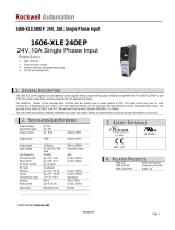
Product Overview
The 1606 Essential line are cost optimized
power supplies without compromising quality,
reliability, and performance. The most
outstanding features of 1606-XLE240E-3 are
the high-efficiency, electronic inrush-current
limitation, active input-transient filter, and
wide-operational temperature range. The small
size is achieved by a synchronous rectification
and further technological design details.
The 1606-XLE240E-3 is equipped with
conformal coated circuit-boards that are
preferred for applications in harsh areas.
The 1606 Essential line includes all essential
basic functions. The devices have a power
reserve of 20% included, which may even be
used continuously at temperatures up to
45 °C (113 °F). Additionally, the
1606-XLE240E-3 can deliver three times the
nominal output current for 10 ms which helps
to trip fuses on faulty output branches.
The power supply features:
• 3x 380
…480V AC wide-range input
• 2 or 3-phase operation possible
• Width only 62 mm (0.039 in.)
• Efficiency up to 92.9% due to synchronous rectifier
• Excellent partial load efficiency
• 20% output power reserves
• Easy fuse tripping due to high overload current
• Input-transient blanking circuit included
• Minimal inrush current surge
• Three input fuses included
• Current sharing feature for parallel use
• Full power between -25 °C...+60 °C (-13 °F...+140 °F)

Rockwell Automation Publication 1606-RM002A-EN-P - March 2019 5
Power Supply - 24V, 10 A, 240 W, Three-phase Input
Figure 1 - Main Approvals
See page 20 for a complete list of approvals.
Attribute Description
Output voltage
Adjustment range
24V DC
24…28V
Nominal
Factory setting 24.1V
Output current 12.0…10.3 A
10.0…8.6 A
7.5…6.5 A
Below 45
°C (113 °F) ambient
60
°C(140 °F) ambient
70 °C(158 °F) ambient
Derate linearly between 45…70
°C
(113…158 °F)
Input voltage AC
Mains frequency
Input current AC
Power factor
3x 380…480V AC
50…60 Hz
0.7/0.6 A
0.53/0.52 A
-15%/+20%
±6%
3x 400/480V
3x 400/480V
AC inrush current 4/4 Apk 3x 400/480V
Efficiency
Losses
92.8/92.9%
18.6/18.3 W
3x 400/480V
3x 400/480V
Hold-up time 34/54 ms 3x 400/480V
Temperature range -25…+70
°C(-13…+158 °F) –
Size (W x H x D) 62 x 124 x 117 mm
(2.44 x 4.88 x 4.60 in.)
Without DIN rail
Weight 750 g (1.65 lb) Without DIN rail
IND. CONT. EQ.
UL 60950-1

6 Rockwell Automation Publication 1606-RM002A-EN-P - March 2019
Power Supply - 24V, 10 A, 240 W, Three-phase Input
Installation Notes
• This device may only be installed and put into operation by qualified
personnel.
• This device does not contain serviceable parts. If damage or malfunction
should occur during installation or operation, immediately turn power off
and send unit to the factory for inspection. The tripping of an internal fuse
is caused by an internal defect.
• Install the device in an enclosure providing protection against electrical,
mechanical, and fire hazards.
• Install the device onto a DIN rail according to EN60715 with the input
terminals on the bottom of the device. Other mounting orientations
require a reduction in output current.
• Make sure that the wiring is correct by following all local and national
codes.
• Use appropriate copper cables that are designed for a minimum operating
temperature of:
– 60 °C (140 °F) for ambient temperatures up to 45 °C (113 °F),
– 75 °C (167 °F) for ambient temperatures up to 60 °C (140 °F),
– and 90 °C (194 °F) for ambient temperatures up to 70 °C (158 °F).
• Verify that all strands of a stranded wire enter the terminal connection.
• Unused screw terminals should be securely tightened.
• The device is designed for pollution degree to areas in controlled
environments. No condensation or frost allowed. The enclosure of the
device provides a degree of protection of IP20.
• The isolation of the device is designed to withstand impulse voltages of
overvoltage category 3 according to IEC 60664-1 for corner grounded
delta systems, the overvoltage category level is reduced to level 2.
ATTENTION: Risk of electrical shock, fire, personal injury, or death.
– Do not use the power supply without proper grounding (Protective Earth). Use
the terminal on the input block for earth connection and not one of the screws on
the housing.
– Turn power off before working on the device. Protect against inadvertent
repowering.
– Do not modify or repair the unit.
– Do not open the unit as high voltages are present inside.
– Use caution to prevent any foreign objects from entering into the housing.
– Do not use in wet locations or in areas where moisture or condensation can be
expected.
BURN HAZARD: Do not touch while applying power, and immediately after
turning off the power. Hot surfaces may cause burns.
WARNING: Substitution of components may impair suitability for this
environment.
Do not disconnect the device or operate the voltage adjustment unless power
has been switched off or the area is known to be non-hazardous.

Rockwell Automation Publication 1606-RM002A-EN-P - March 2019 7
Power Supply - 24V, 10 A, 240 W, Three-phase Input
• The device is designed as Class of Protection I equipment according to
IEC 61140.
• Do not use without a proper PE (Protective Earth) connection.
• The device is suitable to be supplied from TN-, TT-, and IT mains
networks. The voltage between the L terminals and the PE terminal must
not exceed 500V AC continuously.
• A disconnecting means shall be provided for the input of the device.
• The device is designed for convection cooling and does not require an
external fan. Do not obstruct airflow and do not cover ventilation grid.
• The device is designed for altitudes up to 6000 m (19,685 ft). See
Environment
for use above 2000 m (6560 ft).
• Keep the following minimum installation clearances:
– 40 mm (1.57 in.) on top
– 20 mm (0.78 in.) on the bottom
– 5 mm (0.19 in.) left and right side
• Increase the 5 mm (0.19 in.)...15 mm (0.59 in.) in case the adjacent device
is a heat source. When the device is permanently loaded with less than
50%, the 5 mm (0.19 in.) can be reduced to zero.
• The device is designed, tested, and approved for branch circuits up to 32 A
(IEC) and 30 A (UL) without additional protection device. If an external
fuse is utilized, do not use circuit breakers smaller than 6 A
B- or C-Characteristic to avoid a nuisance tripping of the circuit breaker.
• The maximum surrounding air temperature is 70 °C (158 °F). The
operational temperature is the same as the ambient or surrounding air
temperature and is defined 2 cm (7.87 in.) below the device.
• The device is designed to operate in areas between 5% and 95% relative
humidity.

8 Rockwell Automation Publication 1606-RM002A-EN-P - March 2019
Power Supply - 24V, 10 A, 240 W, Three-phase Input
AC Input
Attribute 1606-XLE240E-3
AC input Nom 3V AC/380…480V AC –
AC input range Min 3x 323…576V AC Continuous operation
Min 3x 576…700V AC Max 1 s (occasional)
Allowed voltage L or N to earth Max 500V AC Continuous, IEC 62477-1
Input frequency Nom 50…60 Hz ±6%
Turn-on voltage Typ 3x 260V AC Steady-state value, see Figure 2
.
Shut-down voltage Typ 3x 185V AC Steady-state value, see Figure 2.
External input protection See recommendations in Installation Notes.
Attribute 3x 400V AC 3x 480V AC Description
Input current Typ 0.7 A 0.6 A At 24V, 10 A, per phase, see Figure 4.
Power factor
(1)
Typ 0.53 0.52 At 24V, 10 A, see Figure 5.
Start-up delay Typ 90 ms 90 ms See Figure 3.
Rise time Typ 40 ms 40 ms At 24V, 10 A const. current load, 0mF load capacitance, see Figure 3.
Typ 85 ms 85 ms At 24V, 10 A const. current load, 10mF load capacitance, see Figure 3
.
Turn-on overshoot Max 200 mV 200 mV See Figure 3.
(1) The power factor is the ratio of the true (or real) power to the apparent power in an AC circuit.
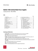
Figure 2 - Input Voltage Range Figure 3 - Turn-on Behavior, Definitions
Turn-on
323V
Rated input
range
V
IN
P
OUT
185V 576V
Shut-down
260V 3x700Vac
< 1s
Start-up
delay
Rise
Time
Overshoot
- 5%
Output
Voltage
Input
Voltage

Rockwell Automation Publication 1606-RM002A-EN-P - March 2019 9
Power Supply - 24V, 10 A, 240 W, Three-phase Input
DC Input
Do not operate the power supply with DC input voltage.
Input Inrush Current
An active inrush limitation circuit limits the input inrush current after turn-on of
the input voltage and after short input voltage interruptions.
The charging current into EMI suppression capacitors is disregarded in the first
microseconds after switch-on.
Figure 6 - Typical Input Inrush Current Behavior at Nominal Load and 25 °C (77 °F) Ambient
Temperature
Figure 4 - Input Current versus Output Load at 24V Figure 5 - Power Factor versus Output Load
Attribute 3x 400V AC 3x 480V AC Description
Inrush
current
Max 10 A peak 10 A peak Temperature independent
Typ 4 A peak 4 A peak
Inrush
energy
Max 0.5 A
2
s1.5 A
2
s
Input current 1A/DIV
Input voltage 500V/DIV
Output voltage
20ms/DIV

10 Rockwell Automation Publication 1606-RM002A-EN-P - March 2019
Power Supply - 24V, 10 A, 240 W, Three-phase Input
DC Output
The output provides a SELV/PELV rated voltage, which is galvanically isolated
from the input voltage.
The device is designed to supply any kind of loads, including unlimited capacitive
and inductive loads.
The output is electronically protected against overload, no-load, and short-
circuits. In case of a protection event, audible noise may occur.
Attribute Description
Output voltage Nom 24V DC –
Adjustment range Min 24…28V AC Guaranteed
Max 30V At clockwise end position of potentiometer.
Factory settings Typ 24.1V ±0.2%, in single use at full load, cold unit
Typ 24.1V ±0.2%, in parallel use at full load, cold unit (results
to 23.9V ±0.7% at 12 A and 25V ±0.2% at no load)
Line regulation Max 10 mV 3 x 323…3 x 576V AC input voltage change
Load regulation Max 100 mV Static value, 0 A…10 A single use mode, static value
Typ 1000 mV Static value, 0 A…10 A parallel use mode, static
value, see Figure 8
.
Ripple and noise
voltage
Max 50 mVpp 20 Hz…20 MHz, 50 Ohms
Output current Nom 12 A
(1)
(1) This current is also available for temperatures up to 70 °C (158 °F) with a duty cycle of 10% and/or not longer than 1 minute every
10 minutes.
At 24V, below 45 °C (113 °F) ambient temperature.
10 A At 24V, below 60 °C (140 °F) ambient temperature.
7.5 A At 24V, at 70 °C (158 °F) ambient temperature.
10.3 A
(1)
At 8V, and an ambient temperature below
45 °C (113 °F).
8.6 A At 28V, at 60 °C (140 °F) ambient temperature.
6.5 A At 28V, at 70 °C (158 °F) ambient temperature.
– Reduce output current linearly between 45 °C…70 °C
(113 °F…158 °F).
Fuse breaking current Typ 23 A Up to 20 ms once every 5 seconds, see Figure 7
. The
fuse breaking is an enhanced transient current,
which helps to trip fuses on faulty output branches.
The output voltage stays above 40V.
Overload behavior – Continuous current See Figure 7.
Overload/Short Circuit
current
Max 23 A Continuous current. See Figure 7
.
Output capacitance Typ 6500 μF Included inside the power supply.
Back-feeding loads Max 35V The unit is resistant and does not show
malfunctioning when a load feeds back voltage to
the power supply. It does not matter whether the
power supply is on or off. The absorbing energy can
be calculated according to the built-in large sized
output capacitor.

Rockwell Automation Publication 1606-RM002A-EN-P - March 2019 11
Power Supply - 24V, 10 A, 240 W, Three-phase Input
Hold-up Time
Figure 7 - Output Voltage versus Output Current, typ. Figure 8 - Output Voltage in Parallel Use Mode, typ.
Output Voltage (Single Use, Typ.)
0
0918
4
8
12
28V
16
20
24
30
A
21123 6 15 24 27
Adjustment
Range
Output Current
Extra
current
for 20 ms
Continuous
current
Factory
setting
Output Voltage (Parallel Use Mode, Typ.)
22V
048
23V
24V
25V
29V
26V
27V
28V
12A1062
Adjustment
Range
Factory
setting
Output Current
Attribute 3x 400V AC 3x 480V AC Description
Typ 34 ms 54 ms At 24V, 10 A, see Figure 9.
Typ 68 ms 108 ms At 24V, 5 A, see Figure 9
.
Min 28 ms 44 ms At 24V, 10 A, see Figure 9.
Min 56 ms 87 ms At 24V, 5 A, see Figure 9.
Figure 9 - Hold-up Time versus Input Voltage Figure 10 - Shut-down Behavior, Definitions
0
320 360 400 440 3x480Vac
20
40
60
100ms
Input Voltage
Hold-up Time at 24Vdc
5
A
,
t
yp
.
10
A
,
t
y
p
.
10A
,
m
i
n
.
5
A
,
m
i
n
.
80
- 5%
Output
Input
Voltage
Hold-up Time
Voltage
L1 L2 L3

12 Rockwell Automation Publication 1606-RM002A-EN-P - March 2019
Power Supply - 24V, 10 A, 240 W, Three-phase Input
Efficiency and Power Loss
Attribute AC 100V 3 AC 480V Description
Efficiency Typ 92.8% 92.9% At 24V, 10 A, 3-phase operation.
Typ 92.4% 92.6% At 24V, 10 A, when using only
two legs of a 3-phase system.
Average
efficiency
(1)
(1) The average efficiency is an assumption for a typical application where the power supply is loaded with 25% of the
nominal load for 25% of the time, 50% of the nominal load for another 25% of the time, 75% of the nominal load
for another 25% of the time and with 100% of the nominal load for the rest of the time.
Typ 92.2% 92.0% 25% at 2.5 A, 25% at 5 A,
25% at 7.55 A, at 10 A, 3-phase
operation
Power losses Typ 2.3 W 2.6 W At 0 A, 3-phase operation.
Typ 11.8 W 11.8 W At 24V, 5 A, 3-phase operation.
Typ 18.6 W 18.3 W At 24V, 10 A, 3-phase operation.
Typ 12.3 W 11.6 W At 24V, 12 A, 3-phase operation.
Figure 11 - Efficiency versus Output Current at 24V, typ., 3-phase
Operation
Figure 12 - Losses versus Output Current at 24V, typ.,
3-phase Operation
Figure 13 - Efficiency versus Input Voltage at 24V, 10 A, typ.,
3-phase Operation
Losses versus Input Voltage at 24V, 10 A, typ., 3-phase
Operation

Rockwell Automation Publication 1606-RM002A-EN-P - March 2019 13
Power Supply - 24V, 10 A, 240 W, Three-phase Input
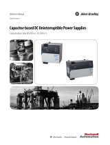
Functional Diagram
Figure 14 - Functional Diagram
Front Side and User
Elements
+
+
-
-
V
OUT
Output
Over-
Voltage
Protection
PFC
Inductor
Inrush
Limiter
Transient
Filter
Input Fuses
Input Filter
Input
Rectier
Output
Voltage
Regulator
Power
Converter
Output
Filter
Output
Power
Manager
Temper-
ature
Shut-
down
DC-ok
LED
L2
L3
L1
Single/
Parallel
POWER SUPPLY
1606-XLE
DC 24V / 10A
+
+
L3
Input
3AC 380-480V
DC ok
1606-XLE240E-3
L2L1
24-28V
18WM
IND.CONT.EQ.
Parallel Use
Single Use
QUALITY
Allen-Bradley
C
D
E
Letter Definition
AOutput terminals - (screw terminals, two pins per pole)
+ Positive output
– Negative (return) output
BInput terminals - (screw terminals)
N, L - Line input
PE - Protective earth input
C Output voltage potentiometer -
Guaranteed adjustment range: 24…28V
Factory set: 24.1V
D Jumper for Parallel Use, Single Use
E DC-OK Relay Contact (push-in terminals)

14 Rockwell Automation Publication 1606-RM002A-EN-P - March 2019
Power Supply - 24V, 10 A, 240 W, Three-phase Input
Connection Terminals
The terminals are IP20 finger safe constructed and suitable for field and factory
wiring.
Daisy Chaining
Daisy chaining (jumping from one power supply output to the next) is allowed as
long as the average output current through one terminal pin does not exceed
25 A. If the current is higher, use a separate distribution terminal block. See
Figure 16
.
Attribute Input and Output
Type Screw termination
Solid wire Max 6 mm
2
Stranded wire Max 4 mm
2
American wire gauge AWG 20…10
Wire diameter, max (including
ferrules)
2.8 mm (0.11 in.)
Tightening torque, recommended 1 Nm, 9 lb-in
Wiring stripping length 7 mm (0.28 in.)
Screwdriver 3.5 mm slotted or Phillips no. 1
Figure 15 - Daisy Chaining of Outputs Figure 16 - Using Distribution Terminals
Load
+
-
Power
Supply
+ +
- -
Output
Power
Supply
+ +
- -
Output
max 25A!
continuous
Distribution
Terminals
Load
+
-
Power
Supply
+ +
- -
Output
Power
Supply
+ +
- -
Output

Rockwell Automation Publication 1606-RM002A-EN-P - March 2019 15
Power Supply - 24V, 10 A, 240 W, Three-phase Input
Lifetime Expectancy and
Mean Time between
Failure
Attribute 100V AC 120V AC Description
Lifetime expectancy
(1)
54,000 h 62,000 h At 24V, 10 A and 40 °C (104 °F), 3-phase operation.
133,000 h 134,000 h At 24V, 5 A and 40 °C (104 °F), 3-phase operation.
41,000 h 47,000 h At 24V, 12 A and 40 °C (104 °F), 3-phase operation.
151,000 h 176,000 h At 24V, 10 A and 25 °C (77 °F), 3-phase operation.
376,000 h 379,000 h At 24V, 5 A and 25 °C (77 °F), 3-phase operation.
116,000 h 133,000 h At 24V, 12 A and 25 °C (77 °F), 3-phase operation.
48,000 h 58,000 h At 24V, 10 A and 40 °C (104 °F), 2-phase operation.
134,000 h 145,000 h At 24V, 5 A and 40 °C (104 °F), 2-phase operation.
36,000 h 42,000 h At 24V, 12 A and 40 °C (104 °F), 2-phase operation.
135,000 h 164,000 h At 24V, 10 A and 25 °C (77 °F), 2-phase operation.
379,000 h 410,000 h At 24V, 5 A and 25 °C (77 °F), 2-phase operation.
102,000 h 119,000 h At 24V, 12 A and 25 °C (77 °F), 2-phase operation.
MTBF
(2)
SN 29500, IEC 61709 975,000 h 985,000 h At 24V, 10 A and 40 °C (104 °F), 3-phase operation.
1,706,000 h 1,723,000 h At 24V, 10 A and 25 °C (77 °F), 3-phase operation.
925,000 h 939,000 h At 24V, 10 A and 40 °C (104 °F), 3-phase operation.
1,633,000 h 1,656,000 h At 24V, 10 A and 25 °C (77 °F), 3-phase operation.
MIL HDBK 217 F 444,000 h 428,000 h At 24V, 10 A and 40 °C (104 °F), 3-phase; Ground Benign GB40.
584,000 h 563,000 h At 24V, 10 A and 25 °C (77 °F), 3-phase; Ground Benign GB25.
100,000 h 100,000 h At 24V, 10 A and 40 °C(104 °F), 3-phase; Ground Fixed GF40.
132,000 h 132,000 h At 24V, 10 A and 25 °C (77 °F), 3-phase; Ground Benign GB25.
436,000 h 423,000 h At 24V, 10 A and 40 °C(104 °F), 2-phase; Ground Fixed GF40.
555,000 h 572,000 h At 24V, 10 A and 25 °C (77 °F), 2-phase; Ground Fixed GF25.
98,000 h 98,000 h At 24V, 10 A and 25 °C (77 °F), 2-phase; Ground Fixed GF25.
129,000 h 129,000 h At 24V, 10 A and 25 °C (77 °F), 2-phase; Ground Fixed GF25.
(1) The Lifetime expectancy that is shown in the table indicates the minimum operating hours (service life) and is determined by the lifetime expectancy of the built-in
electrolytic capacitors. Lifetime expectancy is specified in operational hours and is calculated according to the capacitor’s manufacturer specification. The manufacturer of
the electrolytic capacitors only guarantees a maximum life of up to 15 years (131,400 h). Any number exceeding this value is a calculated theoretical lifetime, which can
be used to compare devices.
(2) MTBF stands for Mean Time Between Failure, which is calculated according to statistical device failures, and indicates reliability of a device. It is the statistical
representation of the likelihood of a unit to fail and does not necessarily represent the life of a product.
The MTBF figure is a statistical representation of the likelihood of a device to fail.
A MTBF figure of for example, 1,000,000 h means that statistically one unit fails every
100 hours if 10,000 units are installed in the field. However, it cannot be determined if the failed unit has been running for 50,000 h or only for 100 h.
For these types of units the MTTF (Mean Time To Failure) value is the same value as the MTBF value.

16 Rockwell Automation Publication 1606-RM002A-EN-P - March 2019
Power Supply - 24V, 10 A, 240 W, Three-phase Input
EMC
EMC Immunity According to Generic Standards EN 61000-6-1 and EN 61000-6-2 Criterion
(1)
(1) Criterion A: Power supply shows normal operation behavior within the defined limits.
Criterion C: Temporary loss of function is possible. Power supply can shut down and restart by itself. No damage or hazard for the
power supply occurs.
Electrostatic discharge EN 61000-4-2 Contact discharge
Air discharge
8 kV
15 kV
Criterion A
Criterion A
Electromagnetic RF field EN 61000-4-3 80 MHz-2.7 GHz 10V/m Criterion A
Fast transients (Burst) EN 61000-4-4 Input lines
Output lines
4 kV
2 kV
Criterion A
Criterion A
Surge voltage on input EN 61000-4-5 L1 ->L2, L2 ->L3, L1 ->L3,
L1/L2/L3->PE
2 kV
4 kV
Criterion A
Criterion A
Surge voltage on output EN 61000-4-5 + ->-
+/- ->PE
500V
1 kV
Criterion A
Criterion A
Conducted disturbance EN 61000-4-6 0.15…80 M Hz 10V Criterion A
Mains voltage dips (Dips
on 3 phases)
EN 61000-4-11 0% of 380V AC
0% of 480V AC
0V AC, 20 ms
0V AC, 20 ms
Criterion A
Criterion A
Mains voltage dips (Dips
on 2 phases)
EN 61000-4-11 40% of 380V AC
40% of 480V AC
70% of 380V AC
70% of 480V AC
200 ms
200 ms
500 ms
500 ms
Criterion A
Criterion A
Criterion A
Criterion A
Voltage interruptions EN 61000-4-11 – 5 s Criterion C
Powerful transients VDE 0160 Over entire load range 1550V, 1.3 ms Criterion A
EMC Emission According to Generic Standards: EN 61000-6-3, EN 610000-6-4
Conducted emission input lines EN 55011, EN 55022
FCC Part 15
CISPR 11, CISPR 22
Class B
Radiated emission EN 55011, EN 55022 Class B
Harmonic input current EN 61000-3-2 Fulfilled for class A equipment
Voltage fluctuations, flicker EN 61000-3-3 Fulfilled
(1)
(1) Tested with constant current loads, non-pulsing.
This device complies with FCC Part 15 rules. Operation is subjected to following two conditions: (1) this device cannot
cause harmful interference, and (2) this device must accept any interference received, including interference that can
cause undesired operation.
Switching Frequency Description
Main converter 60k Hz…140k Hz Output load and input voltage dependent

Rockwell Automation Publication 1606-RM002A-EN-P - March 2019 17
Power Supply - 24V, 10 A, 240 W, Three-phase Input
Environment
Attribute Description
Operational temperature
(1)
(1) Operational temperature is the same as the ambient or surrounding temperature and is defined as the air temperature
2 cm (0.78 in.) below the unit.
-10…+70 °C (+14…+158 °F) The operational temperature is the ambient or
surrounding temperature and is defined as the
air temperature 2 cm (0.78 in.) below the
device.
Storage temperature -40…+85 °C (-40…+185 °F) For storage and transportation.
Output derating
(2)
(2) The de-rating is not hardware controlled. You must stay below the de-rated current limits in order not to overload the unit.
3.2W/°C
6W/°C
15 W/1000 m or 5°C/1000m
9 W/-05 kPa or 3°C/-5 kPa
Range 55…70 °C (131…158 °F)
range 50…70 °C (122…158 °F)
Altitudes up to 2000 m (6560 ft), see Figure 18.
Atmosphere pressures under 80 kPa, see
Figure 18.
Humidity 5...95% r.h. IEC 60068-2-30
Atmospheric pressure 110147 kPa See Figure 18.
Altitude 0…6000 m (0…20,000 ft.) See Figure 18
.
Overvoltage category III IEC 60664-1, altitudes up to 2000 m (6560 ft)
II IEC 60664-1, altitudes 2000...6000 m
(6560 ft...19685 ft) and atmosphere pressures
80...47 kPa
Degree of pollution 2 IEC 62477-1, non conductive
Vibration sinusoidal
(3)
(3) Tested on a DIN Rail according to IEC 60715 with a height of 15 mm (0.59 in.) and thickness of 1.3 mm (0.05 in.).
2-17.8Hz: ±1.6 mm; 17.8-500Hz: 2 g
2 hours/axis
IEC 60068-2-6
Shock
(4)
(4) Tested on a DIN Rail according to IEC 60715 with a height of 15 mm (0.50 in.) and thickness of 1.3 mm (0.05 in.).
30 g 6 ms, 20 g 11 ms
3 bumps/direction, 18 bumps in total
IEC 60068-2-27
LABS compatibility The unit does not release any silicone or other LABS-critical substances and is suitable for
use in paint shops.
Corrosive gases Tested according to ISA-71.04-1985, Severity Level G3 for a service life of minimum
10 years in these environments.
Audible noise Some audible noise may be emitted from the power supply during a no load, overload, or
short circuit condition.
Figure 17 - Output Current versus Ambient Temperature Figure 18 - Output Current versus Altitude at 24V
0
-25 0 20 40
70°C
2A
4A
6A
8A
10A
12A
60
Ambient Temperature
A... Continuous
B... Short term
A
B
Allowed Output Current at 24V
2000m 4000m 6000m
2A
4A
6A
8A
10A
12A
Altitude
Allowed Output Current at 24V
AP
*)
80kPa 62kPa 47kPa110kPa
0m
*) Atmospheric pressure
A... Ambient < 60°C
B... Ambient < 45°C
C... Short term
A
B
C

18 Rockwell Automation Publication 1606-RM002A-EN-P - March 2019
Power Supply - 24V, 10 A, 240 W, Three-phase Input
Protection Features
Safety Features
Attribute Description
Output overvoltage protection Typ 30.5V DC
Max 32V DC
In case of an internal power supply anomaly, a redundant
circuit limits the maximum output voltage. In such a
case, the output shuts down and automatically attempts
to restart.
Degree of protection IP 20 EN/IEC 60529
Over-temperature protection
(1)
(1) Output shuts down with automatic restart. Temperature sensors are installed on critical components inside the unit and turn off
the unit in safety critical situations such as when the ambient temperature is too high, ventilation is obstructed, or the de-rating
requirements are not followed. There is no correlation between the operating temperature and turn-off temperature since this is
dependent on input voltage, load, and installation methods.
Included
Input transient protection MOV (Metal Oxide Varistor)
Internal input fuse Included Not user replaceable.
Attribute Description
Class of protection I IEC 61140. A PE (Protective Earth) connection is
required.
Isolation resistance Min 500 MOhm At delivered condition between input and output,
measured with 500V DC.
At delivered condition between input and PE,
measured with 500V DC.
At delivered condition between output and PE,
measured with 500V DC.
At delivered condition between output and DC-OK
contacts, measured with 500V DC.
PE resistance Max 0.1 Ohm Resistance between PE terminal and the housing in the
area of the DIN rail mounting bracket.
Touch current
(leakage current)
Typ 0.17 mA 3x 400V AC, 50 Hz, TN-,TT-mains
Typ 0.24 mA 3x 480V AC, 60 Hz, TN-,TT-mains
Max 0.22 mA 3x 440V AC, 60 Hz, TN-,TT-mains
Max 0.31 mA 3x 528V AC, 50 Hz, TN-,TT-mains

Rockwell Automation Publication 1606-RM002A-EN-P - March 2019 19
Power Supply - 24V, 10 A, 240 W, Three-phase Input
Dielectric Strength
The output voltage is floating and has no ohmic connection to the ground. The
output is insulated to the input by a double or reinforced insulation.
Type and routine tests are conducted by the manufacturer. Field tests may be
conducted in the field using the appropriate test equipment, which applies the
voltage with a slow ramp (2 s up and 2 s down). Connect all input- terminals
together and all output poles before conducting the test. When testing, set the
cut-off current settings to the value in the table below.
Figure 19 - Dielectric Strength
It is recommended that either the + pole, - pole, or any other part of the output
circuit shall be connected to the earth/ground system. This helps to avoid
situations in which a load starts unexpectedly or can be turned off when
unnoticed earth faults occur.
Attribute A B C
Type test 60 s 2500V AC 3000V AC 500V AC
Factory test 5 s 2500V AC 2500V AC 500V AC
Field test 5 s 2000V AC 2000V AC 500V AC
Cutoff current setting > 10 mA > 10 mA > 30 mA
A
C
B
L1
Input
Earth
Output
-
+
L3
L2

20 Rockwell Automation Publication 1606-RM002A-EN-P - March 2019
Power Supply - 24V, 10 A, 240 W, Three-phase Input
Standards Compliance and
Approvals
EC Declaration of Conformity The CE Marking indicates conformance with the RoHS Directive, low voltage
directive (LVD), and EMC Directive. EN 60950-1, EN 61000-6
ISA 12.12.01 and CSA C22.2, No. 213 RECOGNIZED E244404recognized for use in U.S.A. ISA 12.12.01 and
Canada (C22.2 No. 213)
Hazardous Location Class I Div 2 T4 Groups A,B,C,D and Class I Zone 2 Groups
IIA, IIB and IIC
The unit is suitable for use in Class I Division 2 Groups A, B, C, D locations as
well as for Class I Zone 2 Groups IIA, IIB and IIC locations. Substitution of
components may impair suitability for Class I Division 2 environment. Do
not disconnect equipment unless power has been switched off. Wiring
must be in accordance with Class I, Division 2 wiring methods of the
National Electrical Code, NFPA 70, and in accordance with other local or
national codes.
UL 508 Listed for use as Industrial Control Equipment; U.S.A. (UL 508) and Canada
(C22.2 No. 107-1-01); E-File: E56639
UL 60950-1
2nd edition
Recognized for use as Information Technology Equipment, Level 5; U.S.A.
(UL 60950-1) and Canada (C22.2 No. 60950-1); File: E168663
Applicable for altitudes up to 2000 m.
Marine GL (Germanischer Lloyd) classified
PDA
Environmental category: C, EMC2
Marine and offshore applications
EAC TR Registration Registration for the Eurasian Customs Union Market (Russia, Kazakhstan,
and Belarus)
RoHS Directive Directive 2011/65/EU of the European Parliament and the Council of
June 8th, 2011, on the restriction of the use of certain hazardous
substances in electrical and electronic equipment.
REACH Directive Directive 1907/2006/EU of the European Parliament and the Council of
June 1st, 2007, regarding the Registration, Evaluation, Authorization, and
Restriction of Chemicals (REACH).
IND. CONT. EQ.
/