Page is loading ...

2
Series Operation and Parallel Operation
AEA-13
2.1 Series Operation AEA-13
2.2 Parallel operation/master-slave operation AEA-13
2.3 N+1 Parallel Redundancy Operation AEA-13
3 Life expectancy and Warranty AEA-14
4 Peak current AEA-14
5Ground AEA-15
6 Options AEA-15
6.1 Outline of Options AEA-15
6.2 Medical Isolation Grade AEA-18
1 Function AEA-12
1.1 Input voltage range AEA-12
1.2 Inrush Current Limiting AEA-12
1.3 Overcurrent protection AEA-12
1.4 Peakcurrent protection AEA-12
1.5 Overvoltage protection AEA-12
1.6 Output voltage adjustment range AEA-12
1.7 Thermal protection AEA-12
1.8 Output ripple and ripple noise AEA-12
1.9 Isolation AEA-13
AC-DC Power Supplies Enclosed Type
Instruction Manual
AEA-11
December 27, 2022
www.cosel.co.jp/en/

1 Function
1.1 Input voltage range
¡The range is from 85VAC to 264VAC.
In cases that conform with safety standard, input voltage range is
100VAC to 240VAC (50/60Hz).
¡If input value doesn’t fall within above range, a unit may not oper-
ate in accordance with specications and/or start hunting or fail.
If you need to apply a square waveform input voltage, which is
commonly used in UPS and inverters, please contact us.
¡When the input voltage changes suddenly, the output voltage ac-
curacy might exceed the specication. Please contact us.
If the restart time of the short interruption power failure is less than
3 seconds, perform a thorough evaluation.
¡
A unit can operate under the input voltage dip with derating.
Table1.1 and 1.2 shows the load factors that can be output.
Table1.1 IEC60601-1-2 Maximum output load factor
Voltage dip Duration [ms] Load factor
100VAC →0VAC 20 100%
100VAC →40VAC 100 100%
100VAC →70VAC 500 100%
240VAC →0VAC 20 100%
240VAC →96VAC 100 100%
240VAC →168VAC 500 100%
Table1.2 SEMI F47-0706 Maximum output load factor
Voltage dip Duration [ms] Load factor
100VAC →50VAC 200 100%
100VAC →70VAC 500 100%
100VAC →80VAC 1000 100%
200VAC →100VAC 200 100%
200VAC →140VAC 500 100%
200VAC →160VAC 1000 100%
* 100% Load factor in table 1.1 and 1.2 means the rated current
(forced air cooling) in Specications.
1.2 Inrush Current Limiting
¡An inrush current limiting circuit is built-in.
¡If you need to use a switch on the input side, please select one
that can withstand an input inrush current.
¡Relay technique is used in the inrush current limiting circuit. When
you turn the power ON/OFF repeatedly within a short period of
time, please have enough intervals so that the inrush current limit-
ing circuit becomes operative.
¡When the switch of the input is turned on, the primary inrush cur-
rent and secondary inrush current will be generated because the
relay technique is used for the inrush current limiting circuit.
1.3 Overcurrent protection
¡Overcurrent protection is built-in and comes into effect over 101%
of the peak current in. Overcurrent protection prevents the unit
from short circuit and overcurrent condition.
The unit automatically recovers when the fault condition is cleared.
¡Intermittent Operation Mode
Intermittent operation for overcurrent protection is included in a
part of series. When the overcurrent protection circuit is activated
and the output voltage drops to a certain extent, the output be-
comes intermittent so that the average current will also decrease.
¡
When the overcurrent protection continues, the output will be shut
down.
¡ Output voltage recovers from overcurrent protection by shutting
down the input voltage and waiting more than 3 minutes then turn-
ing on AC input again.
1.4 Peakcurrent protection
¡Peakcurrent protection is built-in (The protection circuit operates
when load current exceeds the rating current and the use deviates
from the condition in Instruction Manual 4).
The output will be recovered automatically after removing causes
of the fault.
1.5 Overvoltage protection
¡An overvoltage protection circuit is built-in. If the overvoltage pro-
tection circuit is activated, shut down the input voltage, wait more
than 3 minutes and turn on the AC input again to recover the out-
put voltage. Recovery time varies depending on such factors as
input voltage value at the time of the operation.
Remarks :
Please avoid applying a voltage exceeding the rated voltage to an
output terminal. Doing so may cause a power supply to malfunc-
tion or fail. If you cannot avoid doing so, for example, if you need
to operate a motor, etc., please install an external diode on the
output terminal to protect the unit.
1.6 Output voltage adjustment range
¡To increase an output voltage, turn a built-in potentiometer clock-
wise. To decrease the output voltage, turn it counterclockwise.
1.7 Thermal protection
¡Thermal protection circuit is built-in and shut down under following
condition.
1When the current and the temperature which exceed from the
derating curve.
2The case FAN stops or air ow is interrupted and the amount of
the wind decreases.
If the thermal protection activates, shut off input voltage, remove
the cause of the overheating, wait for the unit to cool down, and
recycle to recover output voltage.
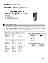
1.8 Output ripple and ripple noise
¡Output ripple noise may be inuenced by measurement environ-
ment, measuring method Fig.1.1 is recommended.
AC-DC Power Supplies Enclosed Type Instruction Manual
AEA-12 December 27, 2022 www.cosel.co.jp/en/

+Vout
-Vout
Load
150mm
C
1
Oscilloscope /
Ripple noise meter
Bw:20MHz
Differential probe
+
C1 : Aluminum electrolytic capacitor 22μF
Fig.1.1 Measuring method of Ripple and Ripple Noise
Remarks :
When GND cable of probe with ux of magnetic force from power
supply are crossing, ripple and ripple noise might not measure
correctly.
Please note the measuring environment.
150mm
Bad example Good example
Fig.1.2. Example of measuring output ripple and ripple noise
1.9 Isolation
¡For a receiving inspection, such as Hi-Pot test, gradually increase
(decrease) the voltage for the start (shut down). Avoid using Hi-
Pot tester with the timer because it may generate voltage a few
times higher than the applied voltage, at ON/OFF of a timer.
2 Series Operation and
Parallel Operation
2.1 Series Operation
¡You can use a power supply in series operation. The output cur-
rent in series operation should be lower than the rated current of a
power supply with the lowest rated current among power supplies
that are serially connected. Please make sure that no current ex-
ceeding the rated current ows into a power supply.
(a) (b)
Load
Power
Supply
+
-
+
-
Power
Supply
Load
Load
Power
Supply
+
-
+
-
Power
Supply
Fig.2.1 Examples of connecting in series operation
¡In series operation, the maximum operative number of units is 9.
The combined output voltage of series operation is 200V.
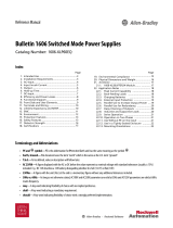
2.2 Parallel operation/master-slave operation
¡As variance of output current drawn from each power supply is
maximum 10%, the total output current must not exceed the value
determined by the following equation.
The rated
current per unit
= X (Number of unit) X0.9
Output current in
parallel operation
When the number of units in parallel operation increases, input
current increases at the same time. Adequate wiring design for
input circuitry is required, such as circuit pattern, wiring and cur-
rent capacity for equipment.
In parallel operation, the maximum operative number of units is 6.
(+)(-)
Load
・・・
+FG N L
CN1 CN2
+ - - + FG N L
CN1 CN2
+ - -+ FG N L
CN1 CN2
+ - -
No.1 No.2 No.6
Implement H-PA-17Implement H-PA-17
Fig.2.2 Connection method in parallel
¡Output voltage in parallel operation is adjustable by using the po-
tentiometer of the “master” unit. Select one power supply to be
the master, and turn the potentiometer of the other, “slave” power
supplies, clockwise to the end. Then use the potentiometer of the
master to adjust output voltage.
¡In series operation or parallel operation, output voltage increases
like stairs due to a delay of the rise time of output voltage at turn
on.
Fig.2.3 Start-up wave form in series and/or parallel operation
Input ON
AC input voltage
Output voltage
2.3 N+1 Parallel Redundancy Operation
¡
You can have N+1 redundancy operation for improving system
reliability.
¡
If you add one extra power supply in parallel operation, even if
one of the power supplies in your system fails, the remaining non-
failed power supplies continue to sustain the system. If one of the
power supplies stops operating, the output voltage may change
about 5%.
¡
When unit replacement is required due to unit failure, input volt-
age for all units must be cut off.
AC-DC Power Supplies Enclosed Type Instruction Manual
AEA-13
December 27, 2022
www.cosel.co.jp/en/

¡
After replacement, please make sure that all wirings are complet-
ed correctly, before re-applying input voltage.
¡
Hot-swap or Hot-plug is not available.
¡
If 2 or more units failed, sufcient power could not be provided to
the system. Therefore, please replace the failed unit immediately
in case where unit failure is found.
¡
If you have any questions about series, parallel and N+1 redun-
dancy operations, please contact us.
3 Life expectancy and
Warranty
¡Life expectancy
Life expectancy is as follows.
Table3.1 Life expectancy
Mount
Average ambient
temperature (yearly)
Life expectancy
Io
[
50% 50<Io[100%
All mounting
direction
Ta [ 30C10 years or more 10 years or more
Ta
=
40C10 years or more
6 years
Ta
=
50C
5 years 3 years
Forced air
Ta [ 30C10 years or more 10 years or more
Ta
=
40C10 years or more
6 years
Ta
=
50C
5 years 3 years
¡Warranty
The warranty is 5 years when average ambient temperature of
year is Ta = 50C or less and load factor is average 50% or less.
However, the warranty is 3 years when average ambient temper-
ature of year is Ta = 50C or less and load factor is series 100%.
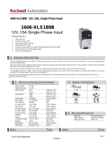
4 Peak current
¡
Peak current can be used at the below condition.
t15sec
lp
Rated peak current
lrms
Rated current
l2
rms t1+t2
l2
Pt1+l22
Lt2
t (sec)
0
lp
: Peak current
lrms :
Effective current
[A]
Output current
t1 t2
lL
: Load current
Fig.4.1 Peak current
Peak current time t1 [sec]
Peak current [%]
0
60
70
80
90
83
88
100
0 1 2 3 4 5 6
AEA800FAEA800FAEA800F
AEA1000FAEA1000FAEA1000FAEA600FAEA600FAEA600F
Fig.4.2 Relation between Peak current time and Peak current
Input voltage [VAC]
Peak current [%]
0
60
70
80
90
75
100
0 9085 170 264
300
AEA800F/1000FAEA800F/1000FAEA800F/1000F
AEA600FAEA600F
AEA600F
Fig.4.3 Derating curve depends on input voltage
¡
Ex. Peak current calculation
Model : AEA600F-24
Conditions :
Vin : 100VAC Cooling method : convection cooling Ta : 40C
I
p
= 30A, t1 = 3sec
IL = 10A, t2 = 40sec
1Calculate Irms
lrms
2=
t1 + t2
lP
2 × t1 + lL
2 × t2=
3+40
302 × 3 + 102 ×40 =155.81
lrms =155.81 =12.48
2Allowed Ip max
Input voltage derating @100VAC = 80%
Peak current time derating @ t1 : 3sec = 80%
Ip max = 52.5 (Rated peak current) ×80%×80% = 33.6A
AC-DC Power Supplies Enclosed Type Instruction Manual
AEA-14 December 27, 2022 www.cosel.co.jp/en/

3Allowed Irms max
Input voltage derating @100VAC = 80%
Ambient temperature derating Ta:40C = 100%
Irms max = 17.5 (Rated current convection cooling) ×80%×100%
= 14A
4Judgment
Ip and Irms do not exceed the maximum condition. Pass
5 Ground
¡
When installing the power supply with your unit, ensure that the
mounting hole FG is connected to safety ground of the unit.
*
It is recommended to electrically connect terminal FG and mount-
ing hole FG to metal chassis for reducing noise.
6 Options
6.1 Outline of Options
¿ -C
-
Except a certain (e.g.terminal, potentiometer), PCB is coated.
¿ -N
-Option -N models come with a cover.
-
Appearance of Option -N models are different from that of stan-
dard models. Please see External View for details.
-
Derating curve for Option -N models is different from that for
standard models. Please see “Derating” for details.
¿ -T
-
Option -T models have vertically positioned screws on a termi-
nal block.
-Please contact us for details about appearance.
Voltage
adjust
+V
-V
FG
AC (N)
AC (L)
Fig.6.1 Example of option -T
¿ -J
-
-J means terminal block is changed to connector.
(Mfr : TE Connectivity).
-Please contact us for details about appearance.
CN501
CN101
Fig.6.2 Example of option -J
A B
A B
1
6
1
3
CN501
CN101
1
3
1
6
Voltage
adjust
Table 6.3 Mating connectors and terminals on CN101 and CN501
Connector Housing Terminal Mfr
CN101 1-178139-5 1-178129-6 1-175218-5 equivalent goods TE Connectivity
CN501 178306-5 178289-6 1-353717-5 equivalent goods
*Keep drawing current per pin below 8.5A
¿ -R3
-
Option -R3 models provide AUX1 (12V), AUX2 (5V),remote ON/
OFF control and alarms (PR,PG alarm).
-Please refer to the optional parts for the dedicated harness.
-Please contact us for details about appearance.
Table 6.1 Pin assignments of CN101
Pin no. Input
A
1 N
2 NC
3 L
B
1 N
2 NC
3 L
Table 6.2 Pin assignments of CN501
Pin no. Output
A
1 +V
2 +V
3 +V
4 –V
5 –V
6 –V
B
1 +V
2 +V
3 +V
4 –V
5 –V
6 –V
AC-DC Power Supplies Enclosed Type Instruction Manual
AEA-15
December 27, 2022
www.cosel.co.jp/en/

CN3
Fig.6.3 Example of option -R3
Table 6.4 Pin assignments of CN3
Pin no. Function
1AUX1 : AUX1 (12V1A)
2AUX1G : AUX1 (GND)
3AUX2 : AUX2 (5V1A)
4AUX2G : AUX2 (GND)
5AUX2 : AUX2 (5V1A)
6AUX2G : AUX2 (GND)
7 RC : Remote ON/OFF
8 RCG : Remote ON/OFF (GND)
9PG : PG Alarm
10 PGG : PG Alarm (GND)
11 PR : PR Alarm
12 PRG : PR Alarm (GND)
Table 6.5 Mating connectors and terminals on CN3
Connector Housing Terminal Mfr
CN3 S12B-
PHDSS
PHDR-
12VS
Reel : SPHD-002T-P0.5
Loose : BPHD-001T-P0.5 *1
BPHD-002T-P0.5 *1
J.S.T.
*1 The manufacturer can offer only ratchet hand tool
¡
AUX1 12V0.3A (convection cooling), 12V1A (forced air)
-
This power supply is equipped with an auxiliary 12V output
AUX1 (12V�5%) for forced air cooling which is available from
CN3.
-
AUX1 is not isolated from the main output circuit.
-
Do not connect AUX1G- to -Vout as current may ow through
AUX1 (g 6.4).
-
Do not exceed the current rating, it may causes malfunction or
failure of the internal circuitry.
Fig.6.4 When using AUX1
12
2
11
1
CN3
+Vout
-Vout
AUX1
AUX1G
Do not connect
×
¡
AUX2 5V0.5A (convection cooling), 5V1A (forced air)
-
Output AUX2 is provided from CN3. AUX2 (5V±5%) can be
used to power up remote control or other circuits.
-
AUX2 has been isolated from other circuit (input, output, FG,
RC).
-
Do not exceed the current rating, it may causes malfunction or
failure of the internal circuitry.
¡Remote ON/OFF
-
You can operate the remote ON/OFF function by sending
signals to CN3. Please see Table 6.6 for specifications and
Fig.6.5 for connecting examples.
-
Remote ON/OFF circuits (RC and RCG) are isolated from input,
output FG and AUX.
-
Please note the following when using the remote ON/OFF func-
tion.
1
Turns on by drawing current to RC.
2
The current own to RC is a 5mA typ (maximum 25mA).
3
If the output voltage is turned off through the remote ON/OFF
circuit, AUX1 stops.
4
If current of a value not listed in Table 6.6 is applied between RC
and RCG, the output voltage may not be generated normally.
5
Please wire carefully. If you wire wrongly, the internal components
of a unit may be damaged.
* If the output of an external power supply is within the range of
4.5 - 12.5V, you do not need a current limiting resistor R1. If
the output exceeds 12.5V, however, please connect the current
limiting resistor R1.
0.005
V1 - (1.1 + Ri × 0.005)
R1 Recommended resister [W]Ri : 780[W]
R1=
Table 6.6 Specications of remote ON/OFF
Fig.6.5 RC circuit example –R3
SW Logic Output on SW short (3mA min)
Output off SW open (0.1mA max)
R1780WRC
RCG
AUX2G
V1
5V
SW
AUX2
CN3
3.5
4.6
3.5
4.6
7
8
(a)
780WRC
RCG
AUX2G
5V
SW
AUX2
CN3
7
8
(b)
Fig.6.5 RC circuit example
AC-DC Power Supplies Enclosed Type Instruction Manual
AEA-16 December 27, 2022 www.cosel.co.jp/en/

¡Alarm
1
PR: abnormal input voltage
2
PG: drop and shut-off of output voltage
Table 6.7 Explanation of alarms
Alarm Output of alarm
PR
When the input voltage is
abnormal (low input voltage),
the alarm signal is output
from CN3.
Open collector method
Good : Low
(0-0.8V, 1mA max)
Bad : High or open
(50V max)
PG
When the rated output
voltage decreases or stops,
the alarm signal is output
from CN3.
Note : When the overcurrent
protection activated,
the PG alarm will be
unstable.
Open collector method
Good : Low
(0-0.8V, 1mA max)
Bad : High or open
(50V max)
The alarm circuits (PR and PG) are isolated from others
(the input, outputs, FG, AUX and other function terminals).
100kW0.1mF
PR or PG
PRG or PGG
Fig 6.6 internal circuit of PR or PG
¿ -T5
-
Acquired UL508.
-
UL 62368-1 and EN62368-1 are compliant. (Only AEA600F)
-
Safety approvals will be invalid with forced air.
-
CN1 and CN2 will be changed to push-in type terminal blocks.
-
AEA600F-32 does not support this option.
Please contact us for any other conditions.
Fig 6.7 Example of option T5
TB5
Voltage adjust
1
TB5
4
Table 6.9 Recommended Ferrule terminals
Type
Manufacturer
Wire size Model Crimp tool
Square type Phoenix
Contact
AWG 20 AI0.5-6WH CRIMPFOX
CENTRUS
6S
AWG 22 AI0.34-6TQ
AWG 24 - 26 AI0.25-6BU
Table 6.10 Applicable wire size (Solid wire,Stranded wire)
Wire size AWG 20 - 26
Wire insulation strip length 6mm
Fig.6.8, Fig6.9 and Fig.6.10 is the how to connect/release the wire.
-How to connect the Ferrule terminals and the solid wire
Step1: Insert the wire until the electrode is not visible. (Refer to the
g.6.8(a).)
Inserting a flat-blade screwdriver into the release hole
makes it easier to insert. (Refer to the g.6.8(b).)
Step2: Pull the wire lightly in order to make sure it is xed.
Wire
Wire
Flat-blade screwdriver
Release hole
Wire insertion
hole
Release hole
Wire insertion
hole
(
a
) (
b
)
Fig.6.8 Connecting method of Ferrule terminal and Solid wire
-How to connect the stranded wire
Step1: Insert a at-blade screwdriver into the release hole. (Refer
to the g.6.9(a).)
Step2: Insert the wire until the electrode is not visible with the at-
blade screwdriver inserted in the release hole. (Refer to the
g.6.9(b).)
Step3: Remove the at-blade screwdriver from the release hole.
(Refer to the g.6.9(c).)
Step4: Pull the wire lightly in order to make sure it is xed.
Table 6.8 Pin assignments of TB5
Pin no. Input
1 VB
2 CB
3VB
4CB
AC-DC Power Supplies Enclosed Type Instruction Manual
AEA-17
December 27, 2022
www.cosel.co.jp/en/

(
a
) (
b
) (
c
)
Fig.6.9 Connecting method of Stranded wire
-How to release the Ferrule terminal, Solid wire and Stranded
wire
Step1: Insert a at-blade screwdriver into the release hole. (Refer
to the g.6.10(a).)
Step2: Remove the wire with the at-blade screwdriver inserted in
the release hole. (Refer to the g.6.10(b).)
Step3: Remove the at-blade screwdriver from the release hole.
(Refer to the g.6.10(c).)
(a) (b) (c)
Fig.6.10 Releasing method of Ferrule terminal, Solid wire and Stranded wire
¿ -P5
-
Overcurrent protection will be changed to shut down mode from
hic-cup mode.
-
Please contact us for any other conditions.
6.2 Medical Isolation Grade
¡AEA series t 2MOPP
¡Type BF
1MOPP 1MOPP
Safety GND
primary secondary
2MOPP
Fig.6.11 Medical Isolation Grade
AC-DC Power Supplies Enclosed Type Instruction Manual
AEA-18 December 27, 2022 www.cosel.co.jp/en/
/