Page is loading ...

C2258M (5/11)
PMCLNBWMT
Tilt Wall Mount
I N S T A L L A T I O N


3 C2258M (5/11)
Contents
Important Safety Instructions ...................................................................................................5
Package Contents ............................................................................................................6
Installing the Wall Plate .......................................................................................................8
Wood Stud Installation ...................................................................................................9
Concrete Installation .....................................................................................................12
Steel Stud Installation ....................................................................................................15
Installing the Mounting Bracket .................................................................................................18
Selecting the Mounting Hardware ..........................................................................................18
Universal Washer Installation ..............................................................................................19
Universal Spacer Installation ............................................................................................... 20
Attaching the Mounting Bracket to the Flat-Panel ..............................................................................21
Lock-It™ Security Barrel Installation (Optional) .....................................................................................22
Attaching the Flat-Panel to the Wall Plate .........................................................................................23
Mounting Bracket Adjustments .................................................................................................24
Leveling Screw Adjustment ................................................................................................24
Locking Screw Adjustment ................................................................................................24
Tilt Adjustment ..............................................................................................................25
Adjusting the Flat-Panel Friction Tilt Angle ....................................................................................25
Adjusting the Flat-Panel to the Original Position ...............................................................................25
Utilizing the Security Barrel ....................................................................................................26
Technical Specifications .......................................................................................................26
Warranty ...................................................................................................................27

4 C2258M (5/11)
List of Illustrations
1 Package Contents ........................................................................................................6
2 Package Contents Continued ...............................................................................................7
3 Locating the Directional Mounting Arrow .....................................................................................8
4 Determining the Mounting Surface ..........................................................................................8
5 Marking the Center of the Wood Studs .......................................................................................9
6 Marking the Upper Mounting Locations ....................................................................................... 9
7 Drilling a Pilot Hole .......................................................................................................10
8 Inserting a Lag Bolt .......................................................................................................10
9 Marking the Remaining Mounting Locations ...................................................................................11
10 Drilling the Remaining Pilot Holes ...........................................................................................11
11 Inserting the Lag Bolts ....................................................................................................12
12 Concrete Wedge Anchors ..................................................................................................12
13 Example of 5/16” Concrete Drill Bit (not included). . . . . . . . . . . . . . . . . . . . . . . . . . . . . . . . . . . . . . . . . . . . . . . . . . . . . . . . . . . . . . . . . . . . . . . . . . . . . . . 12
14 Placing the Wall Plate ..................................................................................................... 13
15 Drilling a Hole in Concrete .................................................................................................13
16 Inserting Concrete Wedge Anchors ..........................................................................................14
17 Attaching Nuts and Washers ...............................................................................................14
18 Steel Stud Components ...................................................................................................15
19 Using a Stud Finder ....................................................................................................... 15
20 Marking Mounting Holes for Steel Stud Anchors ...............................................................................16
21 Drilling Mounting Holes for Steel Stud Anchors ................................................................................16
22 Compressing Steel Stud Anchor Legs. . . . . . . . . . . . . . . . . . . . . . . . . . . . . . . . . . . . . . . . . . . . . . . . . . . . . . . . . . . . . . . . . . . . . . . . . . . . . . . . . . . . . . . . . 17
23 Inserting Steel Stud Anchor Screws .........................................................................................17
24 Marking the Depth Above the Threaded Insert .................................................................................18
25 Determining a Screw with the Correct Length ..................................................................................18
26 Determining a Screw with the Incorrect Length ................................................................................18
27 Installing Universal Washers ...............................................................................................19
28 Universal Washers and Spacers .............................................................................................19
29 Installing Universal Spacers ................................................................................................20
30 Attaching the Mounting Bracket to the Flat-Panel ............................................................................... 21
31 Placing the Locking Screw Through the Security Barrel. . . . . . . . . . . . . . . . . . . . . . . . . . . . . . . . . . . . . . . . . . . . . . . . . . . . . . . . . . . . . . . . . . . . . . . . . . . 22
32 Tightening the Security Barrel Against the Mounting Tab .........................................................................22
33 Sliding the Flat-Panel On the Wall Plate ......................................................................................23
34 Using the Mounting Brackets ...............................................................................................23
35 Adjusting the Leveling Screws ..............................................................................................24
36 Adjusting the Locking Screws. . . . . . . . . . . . . . . . . . . . . . . . . . . . . . . . . . . . . . . . . . . . . . . . . . . . . . . . . . . . . . . . . . . . . . . . . . . . . . . . . . . . . . . . . . . . . . . 24
37 Adjusting the Tilt .........................................................................................................25
38 Using the Security Barrel with a Padlock ......................................................................................26

5 C2258M (5/11)
Important Safety Instructions
1. Read these instructions.
2. Keep these instructions.
3. Heed all warnings.
4. Follow all instructions.
5. Prior to the installation of this product, the installation instructions should be read and completely understood. The installation
instructions must be read to prevent personal injury and property damage. Keep these installation instructions in an easily accessible location for
future reference.
6. Pelco does not warrant against damage caused by the use of any Pelco product for purposes other than those for which it was designed or damage
caused by unauthorized attachments or modifications, and is not responsible for any damages, claims, demands, suits, actions or causes of action of
whatever kind resulting from, arising out of or in any manner relating to any such use, attachments or modifications.
7. The surface must be capable of supporting at least five times the weight of the flat-panel. If not, the structure must be reinforced. The maximum
weight that can be used with this product is 175 lb (79.38 kg). Proper installation procedure by a qualified service technician, as outlined in the
installation instructions, must be adhered to. Failure to do so could result in serious personal injury, or even death.
8. Safety measures must be practiced at all times during the assembly of this product. Use proper safety gear and tools for the assembly procedure to
prevent personal injury.
9. At least two qualified people should perform the assembly procedure. Injury and/or damage can result from dropping or mishandling the flat-panel.
10. If mounting to studs, make sure that the mounting screws are anchored into the center of the studs. Use of an
edge-to-edge stud finder is recommended.
11. Be aware of the mounting environment. If drilling and/or cutting into the mounting surface, always make sure that there are no
electrical wires in wall. Cutting/drilling into an electrical line may cause serious injury.
12. Make sure there are no water lines inside the wall where the mount is to be located. Cutting/drilling into a water line may cause severe water dam-
age to the mounting surface.
13. This product is intended for indoor use only. Use of this product outdoors could lead to product failure and personal injury.
14. Do not install near sources of high heat. Do not install on a structure that is prone to vibration, movement or chance of impact.
This manual may bear the following marks:
This symbol indicates helpful tips and instructive points.
This symbol alerts the reader to potential physical injury or property damage.

6 C2258M (5/11)
PACKAGE CONTENTS
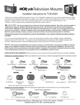
Figure 1. Package Contents
Tilt Wall Mount Parts:
Wall Plate (1 ea.)
Mounting Brackets (2 ea.)
5/16" Flat Washers (6 ea.)
Universal Spacers (24 ea.)
Security Barrel (1 ea.)
Universal Washers (6 ea.)
Thread Depth Indicator (1 ea.)
Pro Mounting Hardware Parts:
M6 Steel Stud Anchors (6 ea.)
5/16" Concrete Wedge Anchors (6 ea.)
5/16" x 3" Lag Bolts (6 ea.)

7 C2258M (5/11)
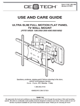
Pan Phillips Screws:
M4x 16 mm (6 ea.)
M4 x 25 mm (6 ea.)
M4 x 30 mm (6 ea.)
M5 x 16 mm (6 ea.)
M5 x 25 mm (6 ea.)
M5 x 30 mm (6 ea.)
Figure 2. Package Contents Continued
M6 x 16 mm (6 ea.)
M6 x 25 mm (6 ea.)
M6 x 30 mm (6 ea.)
M6 x 45 mm (6 ea.)
M8 x 16 mm (6 ea.)
M8 x 25 mm (6 ea.)
M8 x 30 mm (6 ea.)
M8 x 45 mm (6 ea.)
M8 x 70 mm (4 ea.)

8 C2258M (5/11)
Installing the Wall Plate
Directional Mounting Arrow
The Directional Mounting Arrow stamped into the top of the PMCLNBWMT wall mount indicates which edge is the top (Figure 3).
Mounting Safety
Two people are recommended for the installation of this mount.
Figure 3. Locating the Directional Mounting Arrow
What are you installing the PMCLNBWMT mount to (Figure 4)?
• If wood studs, proceed to the Wood Stud Installation section on page 9.
• If a concrete wall, proceed to the Concrete Installation section on page 12.
• If a steel frame, proceed to the Steel Stud Installation section on page 15.
Figure 4. Determining the Mounting Surface
C
onc
rete
St
e
e
l
St
u
d
Wo
o
d
St
u
d

9 C2258M (5/11)
You must secure the wall plate to two wall studs with a minimum of four lag bolts (two lag bolts for each stud found).
1. Use a stud finder (not included) to determine the exact center of wall studs in the vicinity of the wall plate.
2. Use a pencil (not included) to mark the exact center of each of the wall studs (Figure 5).
Figure 5. Marking the Center of the Wood Studs
WOOD STUD INSTALLATION
X
X
Two people are recommended for this step; one person to level the wall plate and another person to mark the wall stud location.
3. Place the wall plate against the wall in the desired viewing location.
4. Adjust the wall plate to align the mount slots in the wall plate with the center of the wall studs.
5. Level the wall plate.
6. Use a pencil to mark the upper right mounting location along the center of the wall stud (Figure 6).
Figure 6. Marking the Upper Mounting Locations

10 C2258M (5/11)
7. Drill a “pilot hole” in the center of the upper right mark using a ¼" drill bit (not included) and power drill (not included) (Figure 7).
Only use a ¼" drill bit when drilling the pilot holes.
Figure 7. Drilling a Pilot Hole
8. Place the wall plate against the wall and align it with the pilot hole.
9. Insert one 5/16" x 3" lag bolt and one 5/16" washer into the upper right mounting hole and tighten using a socket wrench and ½" socket (not included)
(Figure 8).
Do not overtighten the lag bolt.
Figure 8. Inserting a Lag Bolt

11 C2258M (5/11)
10. Level the wall plate.
11. Use a pencil (not included) to mark the remaining three mounting locations along the center of each wall stud (Figure 9).
Figure 9. Marking the Remaining Mounting Locations
Two people are recommended for this step; one person to level the wall plate and another person to drill the pilot holes.
12. Drill a “pilot hole” in the center of each of the marks with a power drill and a ¼" drill bit (Figure 10).
Only use a ¼" drill bit when drilling the pilot holes.
Figure 10. Drilling the Remaining Pilot Holes

12 C2258M (5/11)
13. Insert one 5/16" x 3" lag bolt and one 5/16" washer into each pilot hole (Figure 11).
14. Tighten all lag bolts using a socket wrench and ½" socket.
Do not overtighten the lag bolts when attaching the mount to the wall. Improper installation may result in personal injury or property damage.
Proceed to the Installing the Mounting Bracket section on page 18.
Figure 11. Inserting the Lag Bolts
CONCRETE INSTALLATION
The supplied 5/16" concrete wedge anchors must be used for concrete installation (Figure 12).
You will need a 5/16" concrete drill bit, which is available at your closest hardware store (Figure 13).
Figure 12. Concrete Wedge Anchors
Figure 13. Example of 5/16" Concrete Drill Bit (not included)

13 C2258M (5/11)
Two people are recommended for this step; one person to level the wall plate and another person to mark the mounting locations.
1. Place the wall plate against the wall in the desired viewing location.
2. Level the wall plate.
3. Use a pencil (not included) and mark two upper and two lower mounting locations where you will be drilling holes for the concrete wedge anchors.
Each horizontal location cannot be closer than 12" apart (Figure 14).
4. Set the wall plate to one side in a safe location.
>12”
Figure 14. Placing the Wall Plate
5. Use a power drill (not included) and 5/16" concrete drill (not included) bit to drill a hole at each of the marks (Figure 15).
Figure 15. Drilling a Hole in Concrete

14 C2258M (5/11)
6. Insert a concrete wedge anchor into each hole (Figure 16).
If necessary, lightly tap each concrete wedge anchor into place with a hammer.
7. Remove the nuts and washers from all four concrete wedge anchors.
8. Replace the washers which you removed from the concrete wedge anchors with the 5/16" washers shown in the parts list on page 6.
Figure 16. Inserting Concrete Wedge Anchors
9. Place the wall plate against the wall over the threaded shafts of the concrete wedge anchors.
10. Attach the nuts and 5/16" washers to each of the concrete wedge anchors and tighten using a socket wrench and an M10 socket (not included)
(Figure 17).
Do not overtighten the wedge anchor nuts.
Proceed to the Installing the Mounting Bracket section on page 18.
Figure 17. Attaching Nuts and Washers

15 C2258M (5/11)
STEEL STUD INSTALLATION
The supplied M6 steel stud anchors must be used to install the mount to steel studs. Do not use lag bolts or wood screws
(Figure 18).
Steel Stud Anchor Screw Steel Stud Anchor Sleeve
Figure 18. Steel Stud Components
1. Identify the general location on the wall where you will be mounting your flat-panel.
2. Use a stud finder (not included) to determine the exact center of each steel stud in the vicinity of the mounting location (Figure 19).
3. Use a pencil (not included) and mark the exact center of each steel stud.
X
Figure 19. Using a Stud Finder

16 C2258M (5/11)
4. Place the wall plate against the wall in the desired viewing location.
5. Adjust the wall plate to match the locations of the steel studs.
6. Level the wall plate.
7. Use a pencil (not included) and mark two upper and two lower locations where you will be drilling holes for the steel stud anchors (Figure 20).
8. Set the wall plate to one side in a safe location.
Figure 20. Marking Mounting Holes for Steel Stud Anchors
9. Use a power drill and 7/16" drill bit (not included) to drill a hole at each of the marks (Figure 21).
10. Insert a steel stud anchor into each hole.
If necessary, lightly tap each steel stud anchor into place with a hammer.
Figure 21. Drilling Mounting Holes for Steel Stud Anchors

17 C2258M (5/11)
11. Use a Phillips screwdriver to tighten each steel stud anchor screw until the legs have completely compressed against the back of the steel stud.
The steel stud anchor screw will feel tight when you first begin to turn it until the legs begin to compress. The steel stud anchor screw will then
turn easier for several turns. The steel stud anchor screw will again feel tight when the legs have completely compressed against the back of
the drywall. Stop turning the steel stud anchor screw at that point (Figure 22).
Do not overtighten the steel stud anchor screw.
12. Remove the steel stud anchor screws and set them aside.
Steel stud anchors may come with small paper washers. You may leave them on the screw or discard them. These small paper washers do not
replace standard 5/16" washers.
Figure 22. Compressing Steel Stud Anchor Legs
13. Align the wall plate over the steel stud anchor sleeves.
14. Insert a steel stud anchor screw and a 5/16" washer into each steel stud anchor sleeve (Figure 23).
15. Use a Phillips screwdriver and tighten each steel stud anchor screw until it is just snug.
Do not overtighten the steel stud anchor screws.
Do not use a power drill to tighten the steel stud anchor screws.
Proceed to the Installing the Mounting Bracket section on page 18.
X
X
Figure 23. Inserting Steel Stud Anchor Screws

18 C2258M (5/11)
Installing the Mounting Bracket
1. Insert a small straw or toothpick into the threaded inserts found on the back of the flat-panel.
2. Use a pencil to mark the depth of the threaded insert on the small straw or toothpick.
3. Mark the straw or toothpick 1/8" above the depth of the threaded insert, as shown in Figure 24.
4. Insert the small straw or toothpick into the remaining threaded inserts to compare and verify their depth using the straw or toothpick’s 1/8" allowance
mark.
5. Locate the correct diameter screw for the threaded insert.
If the screw you selected is longer than the 1/8" allowance mark on the small straw or toothpick, as shown in Figure 25 and Figure 26, do not use
this screw. The screw length must not bypass the mark.
6. Test each size of the screws provided.
The correct screws should thread easily into the mounting point and not pull out when tension is applied.
Proceed to the Universal Washer Installation section on page 19.
25
Small Straw or Toothpick
Small Straw
or Toothpick
Small Straw
or Toothpick
Marking the 1/8”
Allowance
Depth Plus 1/8” Allowance
Mark
Depth Plus 1/8” Allowance
Mark
24
26
Figure 24. Marking the Depth Above the Threaded Insert
Figure 25. Finding a Screw with the Correct Length
Figure 26. Finding a Screw with the Incorrect Length
SELECTING THE MOUNTING HARDWARE

19 C2258M (5/11)
UNIVERSAL WASHER INSTALLATION
The Universal Washers and Spacers are designed to accommodate the various M4, M5, M6 and M8 hole sizes required by flat-panels (Figure 27).
Do not place excessive pressure on the back of the flat-panel, as this may damage your flat-panel. The Universal Washer must also be installed
between the head of the mounting screw and the mounting bracket as shown (Figure 28).
Does your flat-panel have recessed mount points, uneven mount points, a curved back or any obstruction near the mount point?
• If Yes, you must install Universal Spacers. Remove the mounting brackets, Universal Washers, and mounting screws from the back of the flat-panel.
Proceed to the Universal Spacer Installation section on page 20.
• If No, skip to the Attaching the Mounting Bracket to the Flat-Panel section on page page 21.
Figure 27. Installing Universal Washers
M8
M5, M6
M4
Figure 28. Universal Washers and Spacers
Flat Panel
Universal Washer
Universal Spacer
Mounting Bracket
Mount Point
Mounting Screw
Mounting Screw
Universal Washer
Mounting Bracket
Flat-Panel
Universal Bracket
Mount Point

20 C2258M (5/11)
UNIVERSAL SPACER INSTALLATION
Universal Spacers allow you to attach the mounting bracket to flat-panels which have recessed or uneven mount points. Each Universal Spacer adds ¼" to
the distance between the mounting bracket and your flat-panel.
The Universal Spacers must be stacked and oriented as shown (Figure 29).
The Universal Spacers must only be installed between the mounting bracket and your flat-panel.
The Universal Spacers will fit M4, M5, M6 and M8 screw sizes.
Proceed to the Attaching the Mounting Bracket to the Flat-Panel section on page 21.
Figure 29. Installing Universal Spacers
1"
¼"
/