H3C LSXM1BSR Installation guide
- Category
- Rack accessories
- Type
- Installation guide

Manual version: 6PW102-20170317 BOM: 3105A03T
i
H3C LSXM1BSR 1U Bottom-Support Rails Installation
Guide
1 Introduction
The H3C LSXM1BSR 1U adjustable bottom-support rails can be adjusted in the range of 630 mm
(24.80 in) to 900 mm (35.43 in).
The bottom-support rails are applicable only to four-post racks. To attach the bottom-support rails to
a rack, make sure the rack depth is in the length range of the bottom-support rails.
2 Installation procedures
WARNING!
To avoid bodily injury, keep the bottom-support rail horizontal and hold the front and rear ends of the
bottom-support rail when you unpack and install a bottom-support rail.
The bottom-support rail installation might vary by rack type. The following installation procedure is for
your reference only.
To install the bottom-support rails:
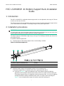
1. Read the signs on the bottom-support rails to avoid making a mistake.
Figure 1 Left bottom-support rail
(1) Bottom-support rail installation hole (2) Sign
(3) Guide rail (4) Front plate installation hole
(5) Locating tab
2. Mark the bottom-support rail installation position on the mounting rails:
The bottom-support rails are installed in the 1 RU region below the device.
a. As shown in Figure 2, alig
n the installation holes in the bottom-support rail with the
uppermost and lowermost standard square holes in the 1 RU region on the mounting rail.
The bottom-support rail has a locating tab on the front and rear ends. You can also align the
locating tab with the auxiliary installation hole in the 1 RU region on the mounting rail.
Figure 2 uses the right bottom-sup
port rail and the right front mounting rail.

Manual version: 6PW102-20170317 BOM: 3105A03T
ii
b. Mark the lowermost standard square hole in the 1RU region on the mounting rail.
c. Mark the standard square holes at the same height on the other three mounting rails.
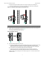
Figure 2 Locating the bottom-support rail installation holes
(1) Auxiliary installation hole (2) Standard square hole for installing the bottom-support rail
3. Install cage nuts on the uppermost and lowermost standard square holes in the marked 1 RU
region on each mounting rail, as shown in Figure 3.
You need to i
nstall a total of eight cage nuts.
Figure 3 Installing a cage nut
4. Attach the bottom-support rails to the rack:
a. Place the right bottom-support rail at the marked position in the rack. Hold both ends of the
right bottom-support rail to compress it so that the locating tabs at both ends of the
bottom-support rail are inserted into the auxiliary installation holes in the mounting rails.
b. Use screws to secure the bottom-support rail to the mounting rails.
c. Perform the same steps to install the left bottom-support rail. Make sure the two
bottom-support rails are at the same height so the device can be placed horizontally.
Install a screw in each mounting hole of the bottom-support rail. You need to install a total of
eight M6 screws.

Manual version: 6PW102-20170317 BOM: 3105A03T
iii
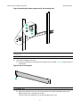
Figure 4 Attaching the bottom-support rail to the mounting rails
(1) Compress the bottom-support rail, making sure both ends of the bottom-support rail are attached to the
mounting rails.
(2) Install screws
5. Attach the front plate to the rack:
a. Orient the front plate so that the front of the plate faces outward. Figure 5 sho
ws the rear of
a front plate.
Figure 5 Rear of a front plate
(1) Installation hole
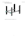
b. Align the installation holes in the front plate with the front plate installation holes in the
bottom-support rails, and fasten the screws.
Two M4 screws are required to secure the front plate to the rack.
1
2

Manual version: 6PW102-20170317 BOM: 3105A03T
iv
Figure 6 Installing the front plate
Copyright © 2015-2017 New H3C Technologies Co., Ltd.
-
 1
1
-
 2
2
-
 3
3
-
 4
4


H3C LSXM1BSR Installation guide
- Category
- Rack accessories
- Type
- Installation guide
Ask a question and I''ll find the answer in the document
Finding information in a document is now easier with AI
Related papers
-
H3C S12501X-AF Quick start guide
-
H3C S7503E Installation, Quick Start
-
-
-
-
-
-
-
-
