Page is loading ...

Argus
®
Installation Instructions
Multi-Beam Panel Antenna 5NPX1006F
Bulleti
Bulletin D701-0005 • Revision D • July 2013 page 1 of 8
CommScope Infrastructure Academy offers installation training
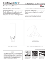
General
This instruction sheet contains all necessary information required to assist in the correct installation
of ARGUS Multi-Beam Panel Antennas.
The following symbols can be found next to text outlining important information.
Please follow the procedure marked with this symbol precisely.
Non-compliance may lead to damage of the product.
Handy tips when installing product.
Unpacking
To make sure no pressure and load on the radome of this antenna in handling and
fixing.
Make sure that the antenna and the accessory items listed below are provided and have not been
damaged during transport.
• Antenna
• Mounting kit
• Installation Instructions (This document)
Mounting Kits Type
Fixed Downtilt F-042-GL-E
Mechanical Downtilt T-045-GL-E
Do not install near power lines. Power lines,
telephone lines, and guy wires look the same.
Assume any wire or line can electrocute you.
Do not install on a wet or windy day or
when lightning or thunder is in the area.
Do not use metal ladder.
Wear shoes with rubber soles and heels.
Wear protective clothing including a
long-sleeved shirt and rubber gloves.

Multi-Beam Panel Antenna 5NPX1006F
Bulletin D701-0005 • Revision D • July 2013 page 2 of 8
Installation Instructions
• Ensure a torque spanner is used when tightening fasteners, see the mounting kit
diagrams on the following pages for the correct torque recommendations.
• Ensure antenna is installed with the connectors and drainage holes at the bottom.
Installation Instructions - Fixed Downtilt Mounting Kit (F-042-GL-E)
Assemble both mounting brackets to the antenna as per Figures 1, 2 & 3 of this document.
Attach the mounting kit assembly to the antenna, before trying to clamp the brackets
to the pole.
The clamp brackets can clamp pipe diameters between 60mm (2.4") & 115mm (4.5").
For typical installations the minimum recommended pipe diameter is 75mm (3").
Figure 1. Correctly Assembled
Mounting Brackets

Bulletin D701-0005 • Revision D • July 2013 page 3 of 8
For Multi-Beam Panel Antenna 5NPX1006F
Figure 2. Fixed Downtilt Mounting Bracket
Assembled to Antenna & pole
Figure 3. Fixed Downtilt Mounting Bracket Exploded Assembly

Multi-Beam Panel Antenna 5NPX1006F
Bulletin D701-0005 • Revision D • July 2013 page 4 of 8
Installation Instructions - Mechanically Adjustable Downtilt Mounting Kit (T-045-
GL-E) , Bracket Spacing 716mm (28.2")
Assemble both mounting brackets as per Figures 4 and 5 (or Figures 7 and 8) of this
document.
1. Attach the lower and upper mounting bracket assemblies to the antenna, before
clamping the brackets to the pole. Downtilt angles of 0° and 2° to 10° in 1°
increments can be obtained with the correct setting of the tilt arm bracket. For 0°
downtilt the tilt arm may be stowed as show in Figure 5.
2. 2°-10° downtilt can be achieved by aligning the corresponding hole in the tilt arm
to the pivot bracket which mates against the mounting pole, as shown in Figure 6 or
Figure 9. The first hole is for 2° downtilt, with each consecutive hole resulting in an
increased inclination of 1°.
3. When the tilt arm is used in the upper antenna bracket as shown in Figures 4 and 5,
the mechanical tilt can be set to 0° or to any angle from 2° to 10° in 1° steps. The
electrical beams emerge from the front of the antenna with a 6° electrical downtilt
so 6° needs to be added to the mechanical tilt to find the actual pointing of the
beams.
4. When the tilt arm is used in the lower mounting bracket as shown in Figure 6, the
mechanical uptilt can be set to 0° or to any angle from 2° to 10° in 1° steps. The
electrical beams emerge from the front of the antenna with a 6° electrical downtilt
so the mechanical uptilt needs to be subtracted from the 6° electrical downtilt to
find the actual downtilt of the beams.
The clamp brackets can clamp pipe diameters between 60mm (2.4") & 115mm (4.5").
For typical installations the minimum recommended pipe diameter is 75mm (3").

Bulletin D701-0005 • Revision D • July 2013 page 5 of 8
For Multi-Beam Panel Antenna 5NPX1006F
6º Downtilt
=0° mechanical
+6° electrical
11º Downtilt
=5° mechanical
+6° electrical
16º Downtilt
=10° mechanical
+6° electrical
Figure 5. Setting mechanical downtilt
Figure 4
Arrangement of mounting kits to provide downtilt (details A and B
in Figure 5)

Multi-Beam Panel Antenna 5NPX1006F
Bulletin D701-0005 • Revision D • July 2013 page 6 of 8
6ºDowntilt
=6° electrical
-0° mechanical
1ºDowntilt
=6° electrical
-5° mechanical
-4ºDowntilt
-4ºDowntilt
= 6° electrical
-10° mechanical
Figure 6
Setting uptilt

Bulletin D701-0005 • Revision D • July 2013 page 7 of 8
For Multi-Beam Panel Antenna 5NPX1006F
Labelling of Antenna Beams
This antenna radiates 5 beams. As mentioned in connection with tilting of the antenna, the beams
point downwards relative to the front face of the antenna at an angle of 6°. In the horizontal plane,
the beams are at azimuth angles of -40° (i.e. 40° to the left of boresight when looking at the
antenna from the rear), -20°, 0°, +20°, +40° (i.e. 40° to the right of boresight when looking at the
antenna from the rear). There are 10 connectors to the antenna, one for each beam of the antenna
at a polarization of +45° and one for each beam at a polarization of -45°.
The pairs of connectors for each beam direction are shown in Figure 7.
The labelling metioned here are not applyable for the antennas series number are,
00000001,00000002,00000003,00000004.
Operation of Antennas
RF Cable
Connection
The 7-16 female connectors fitted to the antenna are designed to fit jumper
cables with a standard 7-16 RF male connector. After ensuring both mating
connectors are dry push the male connector in and tighten the connector
coupling to 23 - 28Nm (17 -21 ft.lb).
If needed or as required by local procedures a weatherproofing kit may
then be fitted to the connection.
If the RF connectors are tightened beyond the recommend torque the RF
connection to the antenna may be damaged.
+40 ºBeam
pointing
+20 ºBeam
pointing
0 ºBeam
pointing
-20ºBeam
pointing
-40ºBeam
pointing
Figure
7
Arrangement of connectors on the base of the antenna.

Multi-Beam Panel Antenna 5NPX1006F
Bulletin D701-0005 • Revision D • July 2013 page 8 of 8
Revision
Changes Date
A First Release 2011-05-10
B Add caution in content of unpacking 2013-03-26
C More clearly define the recommended installation
requirements and warnings & update the figure 2 and 7.
2013-06-19
D Changed drawing template to COMMSCOPE. 2013-07-25
CommScope
1100 CommScope Place SE P.O. Box 339, Hickory, NC 28603-
0339
(828) 324-2200 (800) 982-1708
www.commscope.com/andrew
Customer Service 24 hours
North America: +1-800-255-1479 (toll free)
Any country: +1-779-435-6500
email: acicustomersupportcent[email protected]
Notice: CommScope disclaims any liability or responsibility for the results of improper or unsafe installation, inspection, maintenance, or removal practices.
Aviso: CommScope no acepta ninguna obligación ni responsabilidad como resultado de prácticas incorrectas o peligrosas de instalación, inspección, mantenimiento o retiro.
Avis : CommScope décline toute responsabilité pour les conséquences de procédures d’installation, d’inspection, d’entretien ou de retrait incorrectes ou dangereuses.
Hinweis: CommScope lehnt jede Haftung oder Verantwortung für Schäden ab, die aufgrund unsachgemäßer Installation, Überprüfung, Wartung oder Demontage auftreten.
Atenção: A CommScope abdica do direito de toda responsabilidade pelos resultados de práticas inadequadas e sem segurança de instalação, inspeção, manutenção ou remoção.
Avvertenza: CommScope declina eventuali responsabilità derivanti dell’esecuzione di procedure di installazione, ispezione, manutenzione e smontaggio improprie o poco sicure.
注意:
CommScope 公司申明對於不恰當或不安全的安裝、檢驗、維修或拆卸操作所導致的后果不負任何義務和責任
© 2013 CommScope Bulletin
D701
-
0005
/