Page is loading ...

GLS-LCCT
Crestron SolarSync™ Photosensor
Installation Guide
Description
The GLS-LCCT SolarSync™ Photosensor measures the correlated color temperature
(CCT) and luminosity (lux) of outdoor, natural sunlight. Measurements from the sensor are
relayed to the Crestron
®
control system, which adjusts indoor lighting to match outdoor
lighting conditions.
Additional Resources
Visit the product page on the Crestron website (www.crestron.com)
for additional information and the latest rmware updates. Use a QR
reader application on your mobile device to scan the QR image.
Installation
The GLS-LCCT is designed to be mounted outdoors (on a roof) or indoors (beneath
a skylight). When determining the mounting location, provide the GLS-LCCT with an
unobstructed view of the sky. Use a 1/2 inch knockout (0.885 inch (22.5 mm) actual hole
size) when mounting.
WARNING: To avoid personal injury and equipment damage, consider the following
when mounting the GLS-LCCT outdoors:
• Secure the GLS-LCCT to an IP67 or better J-box to ensure that the enclosure
remains waterproof.
• Use a CSP-LSP Lighting Strike Protector to prevent personal injury during
a lighting strike or damage to the control system and other devices on the
Cresnet
®
network.
• Mount the CSP-LSP inside the building at the point where the Cresnet network
cable enters the building. The CSP-LSP must be properly grounded.
• For installation, wiring, and operation of the CSP-LSP, refer to the CSP-LSP
Installation and Operation Guide (see www.crestron.com/manuals).
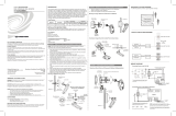
Install the GLS-LCCT:
1. Disconnect power to the system.
2. Seat the o-ring in the groove on the bottom of the sensor.
3. Thread the wire pigtail and the threaded nipple through the knockout. Ensure that the
sensor sits ush with the J-box.
4. Secure the sensor to the J-box using a 1/2-14 NPT locknut. Tighten the locknut to
ensure a proper seal with the J-box.
1/2 inch knockout
(0.885 inch (22.5 mm)
actual hole size)
IP67 or better box
1/2-14 NPT nut
GLS-LCCT
5. Make the Cresnet network connections inside the box using the provided
connectors.
6. Reconnect power to the system.
Wiring Diagram - Indoor Mounting Location
Cresnet to the
control system
Wiring the
GLS-LCCT inside
the J-box.
Terminal Wire Color
24: Red
Y: White
Z: Blue
G: Black
Wiring Diagram - Outdoor Mounting Location
Cresnet to the
control system
Wiring the
GLS-LCCT to the
CSP-LSP inside the
building space.
To a properly
grounded point in
the building.
Wiring the
GLS-LCCT inside
the IP67 or greater
box.
Terminal Wire Color
24: Red
Y: White
Z: Blue
G: Black

Operation
Set up the GLS-LCCT using Crestron Toolbox™ software. The GLS-LCCT has a bi-color
(red/green) LED that is located inside the dome of the device. The LED ashes to identify
the device during setup.
NOTE: Before using the GLS-LCCT, ensure the device is using the latest rmware.
Check for the latest rmware for the GLS-LCCT at www.crestron.com/rmware. Load
the rmware onto the GLS-LCCT using Crestron Toolbox™ software.
Specications
SPECIFICATION DETAILS
Power
Power Consumption 70 mW typical;
5 W (208 mA @ 24 VDC) maximum when
self-heating
Light Sensing
Sensor Technology
Correlated Color Temperature
Light Sensitivity
Field of View
XYZ chromatic white color sensor; measures
color temperature and luminosity consistent
with the CIE 1931 2° Standard Observer color
coordinates
2,000K to 25,000K*
0 to 100,000 lux (0 to 9,290 foot-candles)
360º semispherical
Environmental
Temperature
Humidity
Ingress Protection
Heat Dissipation
-4º to 185 ºF (-20º to 85 ºC)
10% to 90% RH (non-condensing)
IP67 rated per IEC/EN 60529, dust tight and
waterproof
17 Btu/h maximum
* The sensor is factory calibrated to achieve highly accurate correlated color temperature (CCT)
measurements from 2,700K to 5,700K. Values outside this range may vary by a few hundred K or more.
Dimensions
2-11/16 in
(68 mm)
1-25/32 in
(45 mm)
2-25/32 in
(70 mm)
3 ft
(~1 m)
As of the date of manufacture, the product has been tested and found to comply with specications
for CE marking.
The product warranty can be found at www.crestron.com/warranty.
The specic patents that cover Crestron products are listed at www.crestron.com/legal/patents.
Certain Crestron products contain open source software. For specic information, please visit
www.crestron.com/opensource.
Crestron, the Crestron logo, Crestron Toolbox, Cresnet, and SolarSync are either trademarks or
registered trademarks of Crestron Electronics, Inc. in the United States and/or other countries. Other
trademarks, registered trademarks, and trade names may be used in this document to refer to either
the entities claiming the marks and names or their products. Crestron disclaims any proprietary
interest in the marks and names of others. Crestron is not responsible for errors in typography or
photography.
This document was written by the Technical Publications department at Crestron.
©2018 Crestron Electronics, Inc.
Crestron Electronics, Inc. Installation Guide - DOC. 8320A
15 Volvo Drive, Rockleigh, NJ 07647 (2051515)
Tel: 888.CRESTRON 06.18
Fax: 201.767.7576 Specications subject to
www.crestron.com change without notice.
/