Page is loading ...

GLS-LCL
Crestron Green Light
®
Photosensor, Closed-Loop
Installation and Operation Guide
Description
The Crestron
®
GLS-LCL Closed-Loop Photosensor responds to ambient light levels within
an occupied space and provides an analog voltage proportionate to the ambient light
level.
The ambient light measured is the light from any light source in the visible spectrum. The
sensor does not distinguish between natural sunlight and articial light. It contains a
sensor, which is color and spatially corrected to provide a true representation of changes
in lighting levels that the human eye perceives.
The sensor measures the ambient light that actually falls upon it within a 60º cone
extending downward from the sensor (refer to the “Field of View” illustration). This is the
light that is reected to the ceiling from the walls, oor, and furniture.
Field of View
Mounting Location
NOTE: Mount the sensor on a vibration-free surface.
NOTE: The recommended mounting location is above a work space, such as a desk,
conference table, or computer terminal.
NOTE: If ush mounting the sensor into a ceiling for concealed wiring, make sure there
is access to the space above the ceiling and a hole in the ceiling. Refer to the
“Installation” section.
Take care when choosing the mounting location because—depending on the location of
windows, lighting xtures, wall colors, and etc.—the ambient light level will uctuate in
different areas of the room. The ambient light at the doorway can be much less than that
at the windows, corners of the room, or especially on the ceiling. Therefore, it is important
to measure the ambient light level over the workplace.
At the proposed location of the sensor and before installation, measure the daylight levels
on a sunny day.
1. Turn off the lights.
2. Orient a light meter in the same direction the sensor will view.
3. Verify that the light meter reads at least 35 fc for the daylight levels. If the light levels
are less than 35 fc, select another location or reorient the sensor.
Additional Resources
Visit the product page on the Crestron website (www.crestron.com)
for additional information and the latest rmware updates. Use a QR
reader application on your mobile device to scan the QR image.
GLS-LCL Specications
* Power may be taken from the Cresnet
®
bus regardless of interface method.
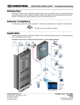
Integrating the GLS-LCL into a Cresnet System via the DIN-IO8
NOTE: The DIN-IO8 can be substituted with any Crestron product with Versiports.
60˚
Wiring
NOTE: Observe the following points:
• Install and use this product in accordance with appropriate electrical codes and
regulations.
• A licensed electrician should install this product.
• Use CRESNET-P or CRESNET-NP wire only.
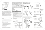
Make connections as described. Refer to the “Wiring Diagrams” section when necessary.
1. Prepare the sensor lead wires by removing 3/4 in (19 mm) of insulation from each
lead to expose bare copper wire. The wire ends must be straight.
2. Determine the length of the low-voltage wires needed to connect power to the
sensor. Use wires suitable for low-voltage wiring according to local electrical codes.
3. Route the low-voltage wires from the GLS-LCL location(s) to the interface device
location(s). Refer to the “Wiring Diagrams” section.
4. Prepare the low-voltage wires by removing 3/4 in (19 mm) of insulation from each
lead to expose bare copper wire. The wire ends must be straight.
5. Connect the low-voltage wires as shown in “Wiring Diagrams” (black to ground, red
to power, and orange to the interface device).
6. Twist the strands of each separate wire connection tightly and push rmly into the
appropriate wire connector.
7. Screw on the connector clockwise, ensuring no bare conductor shows below the
wire connectors.
8. Secure each connector with electrical tape.
Special Programming
To ensure correct processing of the sensor’s output from all interface devices (other than
the GLS-SIM), use the SIMPL program for the control processor to disable the pull-up
resistor built in to the Versiport input connector. This is accomplished by setting the
“pu-disable” digital input signal to a “1.”
Typical Application Diagrams
Integrating the GLS-LCL into a Cresnet System via the GLS-SIM
Crestron 2-series
control processor
GLS-SIM
Cresnet
GLS-LCL
Crestron 2-series
control processor
DIN-IO8
Cresnet
GLS-LCL
Installation
Fasten the GLS-LCL onto the ceiling surface or ush mount it into the ceiling.
Fastened onto the ceiling surface
NOTE: If wiring is to be run exposed along the ceiling, carefully trim the plastic from the
indentation in the side of the outer shell and lay the sensor wires through it before
tightening the shell onto the ceiling.
1. Attach the outer shell to the ceiling at the desired location. Use two #4 screws and
appropriate anchor hardware where necessary.
2. Make all connections as described in the “Wiring” section.
3. Carefully feed the wires into the hole.
4. Press the sensor body into the outer shell until the rim is ush with the shell.
Flush mounted into the ceiling
NOTE: Do not use the outer shell of the sensor.
1. Cut a 2 in (51 mm) diameter hole through the ceiling.
2. Make all connections as described in the “Wiring” section.
3. Carefully feed the wires back through the hole.
4. Press the sensor into the hole until the rim is ush with the ceiling.
SPECIFICATION DETAILS
Power Requirements
Current Consumption 4 mA at 24 Vdc
Cresnet
®
Power Usage <1 W*
Output 0–10 Vdc (0–70 fc)
Recommended Mounting
Location
Directly above work space
Field of View Coverage 60° Cone
Environmental
Temperature 32° to 131 °F (0° to 55 °C)
Humidity 20% to 90% RH (noncondensing)

Troubleshooting
The following table provides corrective actions for possible trouble situations. If further
assistance is required, please contact a Crestron customer service representative.
The product warranty can be found at www.crestron.com/warranty.
The specic patents that cover Crestron products are listed at patents.crestron.com.
Certain Crestron products contain open source software. For specic information, please visit
www.crestron.com/opensource.
Crestron, the Crestron logo, Crestron Green Light, and Cresnet are either trademarks or registered
trademarks of Crestron Electronics, Inc. in the United States and/or other countries. Other trademarks,
registered trademarks, and trade names may be used in this document to refer to either the entities
claiming the marks and names or their products. Crestron disclaims any proprietary interest in the
marks and names of others. Crestron is not responsible for errors in typography or photography.
This document was written by the Technical Publications department at Crestron.
©2016 Crestron Electronics, Inc.
Crestron Electronics, Inc. Installation and Operation Guide - DOC. 6773E
15 Volvo Drive Rockleigh, NJ 07647 (2023020)
Tel: 888.CRESTRON 12.16
Fax: 201.767.7576 Specications subject to
www.crestron.com change without notice.
Wiring Diagrams
NOTE: Use CRESNET-P or CRESNET-NP wire only.
Connecting Sensors to the GLS-SIM
All wires from the sensor to the GLS-SIM must be 24 AWG minimum.
Connecting Sensors to the DIN-IO8
NOTE: The same Crestron power supply MUST be used to power both the sensors and
the interface device (e.g., DIN-IO8). Otherwise, there is a risk of damage to the interface
device.
NOTE: The DIN-IO8 can be substituted with any Crestron product with Versiports.
DIP Switch Settings
INPUT
CHANNEL
DIP
SWITCH
SETTING
1
1 ON
2 OFF*
2
3 ON
4 OFF*
* Setting switches 2 or 4 to ON inverts the polarity, causing the
control signal to read “100%” at 0 V and “0%” at 10 V.
TROUBLE POSSIBLE CAUSE(S) CORRECTIVE ACTION
The lights do not
respond to a change in
ambient light level.
Wiring between the
sensor and the
GLS-SIM (or other
compatible interface) is
incorrect.
Refer to the “Wiring
Diagrams” section.
The sensor location is
improper.
Verify that the sensor
is located such that it
can detect the desired
workspace light levels.
The control system
programming is
incorrect.
Check the logic in the
control processor, or
contact Crestron for
assistance.
The GLS-SIM DIP
switch settings are
incorrect.
Refer to the “Wiring
Diagrams” section.
To control
system
Orange
GLS-LCL
Red
Black
Red
Black
Blue or white
Recommended
maximum wire
length: 250 ft
(76 m).
1 2 3 4
On
Off
Orange
GLS-LCL
Red
Black
To control system
/