
User
Manual
1394 Digital AC
Multi-Axis
Motion Control
System
(Catalog No. 1394-50)
Allen-Bradley

Important User
Information
Because of the variety of uses for the products described in this
publication, those responsible for the application and use of this control
equipment must satisfy themselves that all necessary steps have been
taken to assure that each application and use meets all performance and
safety requirements, including any applicable laws, regulations, codes
and standards.
The illustrations, charts, sample programs and layout examples shown
in this guide are intended solely for purposes of example. Since there
are many variables and requirements associated with any particular
installation, Allen-Bradley does not assume responsibility or liability
(to include intellectual property liability) for actual use based upon the
examples shown in this publication.
Allen-Bradley publication SGI-1.1, Safety Guidelines for the
Application, Installation, and Maintenance of Solid-State Control
(available from your local Allen-Bradley office), describes some
important differences between solid-state equipment and
electromechanical devices that should be taken into consideration when
applying products such as those described in this publication.
Reproduction of the contents of this copyrighted publication, in whole
or in part, without written permission of Allen-Bradley Company, Inc.,
is prohibited.
Throughout this manual we use notes to make you aware of safety
considerations:
Attention statements help you to:
• identify a hazard
• avoid the hazard
• recognize the consequences
Important: Identifies information that is critical for successful
application and understanding of the product.
GML, IMC, Flex I/O, PanelView, Data Highway Plus, SCANport, SLC, SLC 5/03, SLC 5/04, and SLC 5/05 are trademarks of
Allen-Bradley Company, Inc.
PLC is a registered trademark of Allen-Bradley Company, Inc.
!
ATTENTION: Identifies information about practices
or circumstances that can lead to personal injury or
death, property damage or economic loss.

Table of Contents
Publication 1394- 5.0 — May 2000
Preface Who Should Use this Manual . . . . . . . . . . . . . . . . . . . . . . . . . . . . . . . . . . .P-1
Purpose of this Manual . . . . . . . . . . . . . . . . . . . . . . . . . . . . . . . . . . . . . . . .P-1
Contents of this Manual . . . . . . . . . . . . . . . . . . . . . . . . . . . . . . . . . . . . . . .P-2
Related Documentation . . . . . . . . . . . . . . . . . . . . . . . . . . . . . . . . . . . . . . .P-3
Conventions Used in this Manual . . . . . . . . . . . . . . . . . . . . . . . . . . . . . . . .P-3
Module Series Designator . . . . . . . . . . . . . . . . . . . . . . . . . . . . . . . . . . . . .P-3
1394 Product Receiving and Storage Responsibility . . . . . . . . . . . . . . . . .P-4
Allen-Bradley Support . . . . . . . . . . . . . . . . . . . . . . . . . . . . . . . . . . . . . . . . .P-4
Local Product Support . . . . . . . . . . . . . . . . . . . . . . . . . . . . . . . . . . . . . .P-4
Technical Product Assistance . . . . . . . . . . . . . . . . . . . . . . . . . . . . . . . .P-4
Chapter 1
Overview The 1394 System . . . . . . . . . . . . . . . . . . . . . . . . . . . . . . . . . . . . . . . . . . . .1-1
Series Note . . . . . . . . . . . . . . . . . . . . . . . . . . . . . . . . . . . . . . . . . . . . . .1-1
Safety Precautions . . . . . . . . . . . . . . . . . . . . . . . . . . . . . . . . . . . . . . . . . . .1-2
1394 System Overview. . . . . . . . . . . . . . . . . . . . . . . . . . . . . . . . . . . . . . . .1-3
GMC System . . . . . . . . . . . . . . . . . . . . . . . . . . . . . . . . . . . . . . . . . . . . .1-3
CNC Interface System . . . . . . . . . . . . . . . . . . . . . . . . . . . . . . . . . . . . . .1-5
SERCOS System . . . . . . . . . . . . . . . . . . . . . . . . . . . . . . . . . . . . . . . . .1-6
Analog Servo System . . . . . . . . . . . . . . . . . . . . . . . . . . . . . . . . . . . . . .1-7
9/440 CNC System . . . . . . . . . . . . . . . . . . . . . . . . . . . . . . . . . . . . . . . .1-8
What is a 1394 System?. . . . . . . . . . . . . . . . . . . . . . . . . . . . . . . . . . . . . . .1-9
System Modules . . . . . . . . . . . . . . . . . . . . . . . . . . . . . . . . . . . . . . . . .1-10
Axis Modules . . . . . . . . . . . . . . . . . . . . . . . . . . . . . . . . . . . . . . . . . . . .1-11
External Shunt Module (used with 22 kW System) . . . . . . . . . . . . . . .1-11
1326AB Motors . . . . . . . . . . . . . . . . . . . . . . . . . . . . . . . . . . . . . . . . . .1-12
1326AS Motors . . . . . . . . . . . . . . . . . . . . . . . . . . . . . . . . . . . . . . . . . .1-12
1326AH Motors . . . . . . . . . . . . . . . . . . . . . . . . . . . . . . . . . . . . . . . . . .1-13
Drive Interface Module . . . . . . . . . . . . . . . . . . . . . . . . . . . . . . . . . . . . .1-14
DC Link Module . . . . . . . . . . . . . . . . . . . . . . . . . . . . . . . . . . . . . . . . . .1-14
Standard Features of the 1394 . . . . . . . . . . . . . . . . . . . . . . . . . . . . . .1-15
Control . . . . . . . . . . . . . . . . . . . . . . . . . . . . . . . . . . . . . . . . . . . . . . .1-15
Power . . . . . . . . . . . . . . . . . . . . . . . . . . . . . . . . . . . . . . . . . . . . . . .1-16
Integration . . . . . . . . . . . . . . . . . . . . . . . . . . . . . . . . . . . . . . . . . . . .1-16
Chapter 2
Installing Your 1394
(applies to all systems)
Chapter Objectives . . . . . . . . . . . . . . . . . . . . . . . . . . . . . . . . . . . . . . . . . . .2-1
Complying With European Union Directives . . . . . . . . . . . . . . . . . . . . . . . .2-1
EMC Directive . . . . . . . . . . . . . . . . . . . . . . . . . . . . . . . . . . . . . . . . . . . .2-1
Low Voltage Directive . . . . . . . . . . . . . . . . . . . . . . . . . . . . . . . . . . . . . .2-2
Before Mounting Your System. . . . . . . . . . . . . . . . . . . . . . . . . . . . . . . . . . .2-2
Storing Your 1394 Before Installation . . . . . . . . . . . . . . . . . . . . . . . . . . 2-2
Unpacking Modules . . . . . . . . . . . . . . . . . . . . . . . . . . . . . . . . . . . . . . . . . .2-3
System Mounting Requirements. . . . . . . . . . . . . . . . . . . . . . . . . . . . . . . . .2-3
Determining Your System Mounting Hole Layout . . . . . . . . . . . . . . . . .2-4
Mounting Your 1394 Through the Back of the Cabinet . . . . . . . . . . . . . 2-6
Bonding Your System . . . . . . . . . . . . . . . . . . . . . . . . . . . . . . . . . . . . . . . . .2-6
Bonding Modules . . . . . . . . . . . . . . . . . . . . . . . . . . . . . . . . . . . . . . . . . .2-6
Bonding Multiple Subpanels . . . . . . . . . . . . . . . . . . . . . . . . . . . . . . . . .2-8

Publication 1394-5.0 — May 2000
ii Table of Contents
Mounting Your 1394 System . . . . . . . . . . . . . . . . . . . . . . . . . . . . . . . . . . . 2-8
Mounting Your 1394-DCLM . . . . . . . . . . . . . . . . . . . . . . . . . . . . . . . . . . . 2-11
Mounting the External Shunt Resistor for 5 and 10 kW System Modules 2-11
Mounting External Shunt Modules for 22 kW System Modules . . . . . . . . 2-11
Shunt Module Mounting Orientation . . . . . . . . . . . . . . . . . . . . . . . . . . 2-12
Shunt Module Mounted Outside the Cabinet . . . . . . . . . . . . . . . . . . . 2-13
Shunt Module Mounted Inside the Cabinet . . . . . . . . . . . . . . . . . . . . . 2-14
Mounting the Shunt Module. . . . . . . . . . . . . . . . . . . . . . . . . . . . . . . . . 2-15
Mounting Considerations for GMC and GMC Turbo Systems . . . . . . . . . 2-16
Mounting GMC and GMC Turbo Systems Next to Flex I/O . . . . . . . . . 2-16
Chapter 3
Wiring System, Axis, and Shunt
Modules, and Motors
(for all systems)
Chapter Objectives. . . . . . . . . . . . . . . . . . . . . . . . . . . . . . . . . . . . . . . . . . . 3-1
Finding Additional Wiring Information for 1394 Systems . . . . . . . . . . . . . . 3-1
Understanding Basic Wiring Requirements . . . . . . . . . . . . . . . . . . . . . . . . 3-2
Routing High and Low Voltage Cables . . . . . . . . . . . . . . . . . . . . . . . . . 3-3
System Module Wire Sizes . . . . . . . . . . . . . . . . . . . . . . . . . . . . . . . . . . 3-4
Shielding . . . . . . . . . . . . . . . . . . . . . . . . . . . . . . . . . . . . . . . . . . . . . . . . 3-4
EMI/RFI Shielding . . . . . . . . . . . . . . . . . . . . . . . . . . . . . . . . . . . . . . . . . 3-4
EMI/RFI Bonding . . . . . . . . . . . . . . . . . . . . . . . . . . . . . . . . . . . . . . . . . 3-4
Input Power Conditioning . . . . . . . . . . . . . . . . . . . . . . . . . . . . . . . . . . . 3-5
Determining Your Type of Input Power . . . . . . . . . . . . . . . . . . . . . . . . . . . . 3-6
Grounded Power Configuration . . . . . . . . . . . . . . . . . . . . . . . . . . . . . . . 3-6
Ungrounded Power Configuration . . . . . . . . . . . . . . . . . . . . . . . . . . . . . 3-7
Setting the Ground Jumper in a 5 or 10 kW System Module for
Ungrounded Power Configurations . . . . . . . . . . . . . . . . . . . . . . . . . 3-8
Setting the Ground Jumper in a 22 kW System Module for
Ungrounded Power Configurations . . . . . . . . . . . . . . . . . . . . . . . . . 3-9
Grounding Your 1394 System . . . . . . . . . . . . . . . . . . . . . . . . . . . . . . . . . 3-12
Grounding your System to the Subpanel . . . . . . . . . . . . . . . . . . . . . . 3-12
Grounding Multiple Subpanels . . . . . . . . . . . . . . . . . . . . . . . . . . . . . . 3-13
Wiring System Module Power . . . . . . . . . . . . . . . . . . . . . . . . . . . . . . . . . 3-13
Terminal Block Locations for 5 and 10 kW System Module
(Series A and B) . . . . . . . . . . . . . . . . . . . . . . . . . . . . . . . . . . . . . . . . . 3-14
Connector Locations for 5 and 10 kW System Module (Series C) . . . 3-15
Terminal Block Locations for a 22 kW System Module . . . . . . . . . . . . 3-16
Required Tools and Equipment . . . . . . . . . . . . . . . . . . . . . . . . . . . . . . 3-17
Connecting Power Wiring for 5 and 10 kW (Series A and B)
and 22 kW System Modules . . . . . . . . . . . . . . . . . . . . . . . . . . . . . 3-17
Connecting Power Wiring for 5 and 10 kW System Modules
(Series C) . . . . . . . . . . . . . . . . . . . . . . . . . . . . . . . . . . . . . . . . . . . . 3-18
Connecting Motor Power to Axis Modules . . . . . . . . . . . . . . . . . . . . . . . . 3-19
Connecting Thermal and Brake Leads to Axis Modules . . . . . . . . . . . 3-20
Required Tools and Equipment . . . . . . . . . . . . . . . . . . . . . . . . . . . . . . 3-20
Wiring Motor Power, Thermals and Brakes . . . . . . . . . . . . . . . . . . . . . 3-21
Connecting Feedback to System Modules. . . . . . . . . . . . . . . . . . . . . . . . 3-24
Connecting Your Motor Cables to Motors. . . . . . . . . . . . . . . . . . . . . . . . . 3-26
Connecting Your External Shunt Resistor . . . . . . . . . . . . . . . . . . . . . . . . 3-26
Connecting Your External Shunt Resistor (Series A and B) . . . . . . . . 3-27
Connecting Your External Shunt Resistor (Series C) . . . . . . . . . . . . . 3-28

Publication 1394-5.0 — May 2000
Table of Contents iii
Connecting Your Shunt Module (required for 22 kW system) . . . . . . . . . 3-28
Required Tools and Equipment . . . . . . . . . . . . . . . . . . . . . . . . . . . . . 3-28
Wiring the Shunt Module Power . . . . . . . . . . . . . . . . . . . . . . . . . . . . . 3-29
Wiring Shunt Module Fan Power . . . . . . . . . . . . . . . . . . . . . . . . . . . . 3-33
Chapter 4
Wiring 1394 GMC and GMC Turbo
Systems
Chapter Objectives . . . . . . . . . . . . . . . . . . . . . . . . . . . . . . . . . . . . . . . . . . 4-1
Finding Additional Wiring Information for 1394 Systems . . . . . . . . . . . . . . 4-1
Understanding GMC and GMC Turbo Wiring and Connections . . . . . . . . 4-1
Understanding Input Wiring Board Layout. . . . . . . . . . . . . . . . . . . . . . . . . 4-2
Using the Terminal Operating Tool to Insert Wires . . . . . . . . . . . . . . . . 4-4
Input Wiring Board Signal Descriptions . . . . . . . . . . . . . . . . . . . . . . . . 4-5
Connecting Your Communication Cables . . . . . . . . . . . . . . . . . . . . . . . . . 4-7
Encoder Feedback Wiring . . . . . . . . . . . . . . . . . . . . . . . . . . . . . . . . . 4-10
Serial Communications . . . . . . . . . . . . . . . . . . . . . . . . . . . . . . . . . . . 4-11
Data Highway Connection . . . . . . . . . . . . . . . . . . . . . . . . . . . . . . . . . 4-13
AxisLink . . . . . . . . . . . . . . . . . . . . . . . . . . . . . . . . . . . . . . . . . . . . . . . 4-14
GMC Turbo System . . . . . . . . . . . . . . . . . . . . . . . . . . . . . . . . . . . . . . 4-15
Remote I/O . . . . . . . . . . . . . . . . . . . . . . . . . . . . . . . . . . . . . . . . . . . . . 4-16
Flex I/O . . . . . . . . . . . . . . . . . . . . . . . . . . . . . . . . . . . . . . . . . . . . . . . . 4-16
SLC Interface . . . . . . . . . . . . . . . . . . . . . . . . . . . . . . . . . . . . . . . . . . . 4-17
Connecting a GMC and GMC Turbo to a 1394-DIM . . . . . . . . . . . . . . . . 4-19
1394-DIM System Example . . . . . . . . . . . . . . . . . . . . . . . . . . . . . . . . 4-19
1394-DIM with 1398-DDM-
xxx
System Example . . . . . . . . . . . . . . . . 4-20
1394-DIM Configurations . . . . . . . . . . . . . . . . . . . . . . . . . . . . . . . . . . 4-21
Configuration Examples . . . . . . . . . . . . . . . . . . . . . . . . . . . . . . . . . . . 4-22
1394-System Module Input Power Wiring When
Not Using Axis Modules . . . . . . . . . . . . . . . . . . . . . . . . . . . . . . . . . 4-24
Understanding DIM Signals . . . . . . . . . . . . . . . . . . . . . . . . . . . . . . . . . . . 4-24
DROK . . . . . . . . . . . . . . . . . . . . . . . . . . . . . . . . . . . . . . . . . . . . . . . . . 4-24
Drive Enable Output . . . . . . . . . . . . . . . . . . . . . . . . . . . . . . . . . . . . . . 4-25
Analog Output . . . . . . . . . . . . . . . . . . . . . . . . . . . . . . . . . . . . . . . . . . 4-25
Wiring and Configuring an External Drive to the 1394-DIM. . . . . . . . . . . 4-26
Connecting the Remote Drive to the DIM Connector . . . . . . . . . . . . . 4-26
Connecting the Position Feedback Encoder to the Feedback Input . . 4-29
Connecting the DIM Ground Wire to the 1394 System Ground . . . . . 4-30
Installing the Resolver Feedback Input Plug . . . . . . . . . . . . . . . . . . . 4-30
Chapter 5
Wiring Your 1394 Analog Servo System Chapter Objectives . . . . . . . . . . . . . . . . . . . . . . . . . . . . . . . . . . . . . . . . . . 5-1
Finding Additional Wiring Information for 1394 Systems . . . . . . . . . . . . . . 5-1
Understanding Analog Servo Wiring and Connections . . . . . . . . . . . . . . . 5-1
Input Wiring Board Layout . . . . . . . . . . . . . . . . . . . . . . . . . . . . . . . . . . . . . 5-2
Using the Terminal Operating Tool to Insert Wires . . . . . . . . . . . . . . . . 5-2
Input Wiring Board Signal Descriptions . . . . . . . . . . . . . . . . . . . . . . . . 5-4
Connecting AQB and SCANport Cables . . . . . . . . . . . . . . . . . . . . . . . . . . 5-5
Analog Servo Encoder (A Quad B) Wiring . . . . . . . . . . . . . . . . . . . . . . 5-5
SCANport Adapter . . . . . . . . . . . . . . . . . . . . . . . . . . . . . . . . . . . . . . . . 5-7

Publication 1394-5.0 — May 2000
iv Table of Contents
Chapter 6
Commissioning 1394 GMC and GMC
Turbo Systems
Chapter Objectives. . . . . . . . . . . . . . . . . . . . . . . . . . . . . . . . . . . . . . . . . . . 6-1
General Startup Precautions . . . . . . . . . . . . . . . . . . . . . . . . . . . . . . . . . . . 6-1
Applying Power to the System . . . . . . . . . . . . . . . . . . . . . . . . . . . . . . . . . . 6-2
Setting Up Your System Using GML Commander . . . . . . . . . . . . . . . . . . . 6-3
Before You Begin . . . . . . . . . . . . . . . . . . . . . . . . . . . . . . . . . . . . . . . . . 6-3
Preparing the System . . . . . . . . . . . . . . . . . . . . . . . . . . . . . . . . . . . . . . 6-4
Setting Up Your System Using GML 3.
x
.
x
. . . . . . . . . . . . . . . . . . . . . . . . . 6-5
Before You Begin . . . . . . . . . . . . . . . . . . . . . . . . . . . . . . . . . . . . . . . . . 6-5
Preparing the System . . . . . . . . . . . . . . . . . . . . . . . . . . . . . . . . . . . . . . 6-5
Chapter 7
Commissioning Your 1394 Analog
Servo System
Chapter Objectives. . . . . . . . . . . . . . . . . . . . . . . . . . . . . . . . . . . . . . . . . . . 7-1
General Startup Precautions . . . . . . . . . . . . . . . . . . . . . . . . . . . . . . . . . . . 7-1
Setting Up Your 1394 Analog Servo System . . . . . . . . . . . . . . . . . . . . . . . 7-2
Before You Begin . . . . . . . . . . . . . . . . . . . . . . . . . . . . . . . . . . . . . . . . . 7-2
Exiting Before You’re Finished . . . . . . . . . . . . . . . . . . . . . . . . . . . . . 7-2
Continuing From Where You Left Off . . . . . . . . . . . . . . . . . . . . . . . . 7-2
Removing and Re-Applying Power . . . . . . . . . . . . . . . . . . . . . . . . . . . . 7-3
Setting Up at the System Level . . . . . . . . . . . . . . . . . . . . . . . . . . . . . . . 7-4
Setting Up Analog Test Points . . . . . . . . . . . . . . . . . . . . . . . . . . . . . . . . 7-5
Defining Your Motor . . . . . . . . . . . . . . . . . . . . . . . . . . . . . . . . . . . . . . . 7-5
Defining a Reference Source for Your Axes . . . . . . . . . . . . . . . . . . . . . 7-6
Defining Analog Velocity . . . . . . . . . . . . . . . . . . . . . . . . . . . . . . . . . . 7-7
Defining Analog Torque . . . . . . . . . . . . . . . . . . . . . . . . . . . . . . . . . . 7-8
Defining Digital Velocity . . . . . . . . . . . . . . . . . . . . . . . . . . . . . . . . . . 7-8
Defining Digital Torque . . . . . . . . . . . . . . . . . . . . . . . . . . . . . . . . . . . 7-9
Defining Limits . . . . . . . . . . . . . . . . . . . . . . . . . . . . . . . . . . . . . . . . . . 7-10
Auto Tuning . . . . . . . . . . . . . . . . . . . . . . . . . . . . . . . . . . . . . . . . . . . . . 7-11
Before You Perform an Auto Tune . . . . . . . . . . . . . . . . . . . . . . . . . . 7-11
Performing the Auto Tune . . . . . . . . . . . . . . . . . . . . . . . . . . . . . . . . 7-11
Chapter 8
Configuring Your 1394 Analog Servo
System
Chapter Objectives. . . . . . . . . . . . . . . . . . . . . . . . . . . . . . . . . . . . . . . . . . . 8-1
Where to Look for Other Programming Information . . . . . . . . . . . . . . . . . . 8-1
Conventions Used in this Chapter . . . . . . . . . . . . . . . . . . . . . . . . . . . . . . . 8-2
Understanding Analog Servo System Parameters. . . . . . . . . . . . . . . . . . . 8-3
1394 Analog Servo Software Diagrams . . . . . . . . . . . . . . . . . . . . . . . . . . 8-28
Chapter 9
Troubleshooting Chapter Objectives. . . . . . . . . . . . . . . . . . . . . . . . . . . . . . . . . . . . . . . . . . . 9-1
Understanding How to Detect a Problem. . . . . . . . . . . . . . . . . . . . . . . . . . 9-2
Understanding System and Axis Module LEDs . . . . . . . . . . . . . . . . . . . . . 9-2
Understanding System Faults . . . . . . . . . . . . . . . . . . . . . . . . . . . . . . . . . . 9-5
Finding GMC Faults . . . . . . . . . . . . . . . . . . . . . . . . . . . . . . . . . . . . . . . 9-5
Viewing Instantaneous Status . . . . . . . . . . . . . . . . . . . . . . . . . . . . . 9-5
Viewing Continuous Status . . . . . . . . . . . . . . . . . . . . . . . . . . . . . . . . 9-6
Finding Analog Servo System Faults . . . . . . . . . . . . . . . . . . . . . . . . . . 9-7

Publication 1394-5.0 — May 2000
Table of Contents v
Finding 9/440 Faults . . . . . . . . . . . . . . . . . . . . . . . . . . . . . . . . . . . . . . . 9-7
Finding CNC Interface Faults . . . . . . . . . . . . . . . . . . . . . . . . . . . . . . . . 9-8
Understanding GMC Turbo and GMC Controller Faults. . . . . . . . . . . . . . . 9-9
Understanding Analog Servo System Module Faults . . . . . . . . . . . . . . . 9-10
Understanding Analog Servo System Axis Faults . . . . . . . . . . . . . . . 9-12
Troubleshooting General System Problems. . . . . . . . . . . . . . . . . . . . . . . 9-13
Replacing System and Axis Modules . . . . . . . . . . . . . . . . . . . . . . . . . . . 9-16
Before You Begin . . . . . . . . . . . . . . . . . . . . . . . . . . . . . . . . . . . . . . . . 9-16
Removing an Axis Module . . . . . . . . . . . . . . . . . . . . . . . . . . . . . . . . . 9-17
Installing a Replacement Axis Module . . . . . . . . . . . . . . . . . . . . . . . . 9-18
Removing a System Module . . . . . . . . . . . . . . . . . . . . . . . . . . . . . . . 9-19
Installing a Replacement System Module . . . . . . . . . . . . . . . . . . . . . 9-20
Replacing System Modules of the Same Series . . . . . . . . . . . . . . 9-22
Replacing System Modules of a Different Series . . . . . . . . . . . . . . 9-22
Completing Connections and Downloading Parameters . . . . . . . . 9-22
Checking for a Blown Fuse in the 1394-DCLM . . . . . . . . . . . . . . . . . . . . 9-23
Replacing the 1394 Shunt Module Fuse . . . . . . . . . . . . . . . . . . . . . . . . . 9-25
Replacing the 1394-SR10A Fuse . . . . . . . . . . . . . . . . . . . . . . . . . . . . 9-25
Replacing the 1394-SR9A, -SR9AF, -SR36A, and -SR36AF Fuse . . 9-26
Replacing the AM50 and AM75 Axis Module Fan . . . . . . . . . . . . . . . . . . 9-28
Removing the Fan . . . . . . . . . . . . . . . . . . . . . . . . . . . . . . . . . . . . . . . 9-28
Installing the New Fan . . . . . . . . . . . . . . . . . . . . . . . . . . . . . . . . . . . . 9-31
Appendix A
Specifications Chapter Objectives . . . . . . . . . . . . . . . . . . . . . . . . . . . . . . . . . . . . . . . . . . A-1
System Specifications . . . . . . . . . . . . . . . . . . . . . . . . . . . . . . . . . . . . . . . . A-1
Certification . . . . . . . . . . . . . . . . . . . . . . . . . . . . . . . . . . . . . . . . . . . . . A-1
System Modules . . . . . . . . . . . . . . . . . . . . . . . . . . . . . . . . . . . . . . . . . . A-2
Axis Modules . . . . . . . . . . . . . . . . . . . . . . . . . . . . . . . . . . . . . . . . . . . . A-3
Contact Ratings . . . . . . . . . . . . . . . . . . . . . . . . . . . . . . . . . . . . . . . . . . A-3
DC Link Module . . . . . . . . . . . . . . . . . . . . . . . . . . . . . . . . . . . . . . . . . . A-4
Drive Interface Module . . . . . . . . . . . . . . . . . . . . . . . . . . . . . . . . . . . . . A-4
Filters . . . . . . . . . . . . . . . . . . . . . . . . . . . . . . . . . . . . . . . . . . . . . . . . . . A-4
User-Supplied Contactor (M1) . . . . . . . . . . . . . . . . . . . . . . . . . . . . . . . A-5
User-Supplied Line Input Fusing . . . . . . . . . . . . . . . . . . . . . . . . . . . . . A-5
User-Supplied 24V Logic Input Power . . . . . . . . . . . . . . . . . . . . . . . . . A-5
Input Transformer for 24V Control Power . . . . . . . . . . . . . . . . . . . . . . . A-6
User-Supplied 5V Auxiliary Encoder Power Supply . . . . . . . . . . . . . . . A-6
Circuit Breakers . . . . . . . . . . . . . . . . . . . . . . . . . . . . . . . . . . . . . . . . . . A-6
External Shunt Resistor Kit for 5 and 10 kW Systems . . . . . . . . . . . . . A-8
1394 Shunt Module for the 22 kW System . . . . . . . . . . . . . . . . . . . . . . A-8
Environmental Specifications. . . . . . . . . . . . . . . . . . . . . . . . . . . . . . . . . . . A-9
Power Dissipation . . . . . . . . . . . . . . . . . . . . . . . . . . . . . . . . . . . . . . . . . . A-10
System Modules . . . . . . . . . . . . . . . . . . . . . . . . . . . . . . . . . . . . . . . . . A-10
Axis Modules . . . . . . . . . . . . . . . . . . . . . . . . . . . . . . . . . . . . . . . . . . . A-10
DC Link Module . . . . . . . . . . . . . . . . . . . . . . . . . . . . . . . . . . . . . . . . . A-11
Drive Interface Module . . . . . . . . . . . . . . . . . . . . . . . . . . . . . . . . . . . . A-11
Internal Shunt Resistor for the 5 and 10 kW System (standard) . . . . A-11
Communication Specifications. . . . . . . . . . . . . . . . . . . . . . . . . . . . . . . . . A-11
Encoder Input Specifications . . . . . . . . . . . . . . . . . . . . . . . . . . . . . . . A-11

Publication 1394-5.0 — May 2000
vi Table of Contents
Dedicated Discrete I/O Specifications . . . . . . . . . . . . . . . . . . . . . . . . A-12
Serial I/O Specifications . . . . . . . . . . . . . . . . . . . . . . . . . . . . . . . . . . . A-12
DH-485 Specifications . . . . . . . . . . . . . . . . . . . . . . . . . . . . . . . . . . . . A-13
Flex I/O Specifications . . . . . . . . . . . . . . . . . . . . . . . . . . . . . . . . . . . . A-13
GMC System Specifications . . . . . . . . . . . . . . . . . . . . . . . . . . . . . . . . A-14
Remote I/O Adapter Specifications . . . . . . . . . . . . . . . . . . . . . . . . . . . A-15
AxisLink Specifications . . . . . . . . . . . . . . . . . . . . . . . . . . . . . . . . . . . . A-16
Dimensions . . . . . . . . . . . . . . . . . . . . . . . . . . . . . . . . . . . . . . . . . . . . . . . A-17
1394 System Module Dimensions . . . . . . . . . . . . . . . . . . . . . . . . . . . A-17
Axis Module Dimensions . . . . . . . . . . . . . . . . . . . . . . . . . . . . . . . . . . A-18
Filter Dimensions . . . . . . . . . . . . . . . . . . . . . . . . . . . . . . . . . . . . . . . . A-20
External Shunt Dimensions . . . . . . . . . . . . . . . . . . . . . . . . . . . . . . . . A-22
Motor Dimensions . . . . . . . . . . . . . . . . . . . . . . . . . . . . . . . . . . . . . . . . A-25
Servo Motor Performance Data . . . . . . . . . . . . . . . . . . . . . . . . . . . . . . . . A-32
1326AB Performance Data . . . . . . . . . . . . . . . . . . . . . . . . . . . . . . . . . A-32
1326AS Performance Data . . . . . . . . . . . . . . . . . . . . . . . . . . . . . . . . . A-33
Appendix B
Interconnect and CE Diagrams Chapter Objectives. . . . . . . . . . . . . . . . . . . . . . . . . . . . . . . . . . . . . . . . . . . B-1
GMC, Analog Servo, and CNC Interface Interconnect Diagrams. . . . . . . . B-2
1394 GMC Interconnections . . . . . . . . . . . . . . . . . . . . . . . . . . . . . . . . . B-3
1394 Analog Servo Interconnections . . . . . . . . . . . . . . . . . . . . . . . . . . B-9
1394 CNC Interconnections . . . . . . . . . . . . . . . . . . . . . . . . . . . . . . . . B-12
Thermal Interconnect Diagrams. . . . . . . . . . . . . . . . . . . . . . . . . . . . . . . . B-14
1394 GMC Systems (1394
x
-SJT
xx
-C and -T) . . . . . . . . . . . . . . . . . . B-15
1394 GMC Systems (1394C-SJT
xx
-L) . . . . . . . . . . . . . . . . . . . . . . . . B-19
1394 Analog Servo Systems (1394
x
-SJT
xx
-A) . . . . . . . . . . . . . . . . . B-21
Cable Pin-outs . . . . . . . . . . . . . . . . . . . . . . . . . . . . . . . . . . . . . . . . . . . . . B-23
1326 Cable Pin-outs . . . . . . . . . . . . . . . . . . . . . . . . . . . . . . . . . . . . . . B-23
1394 Cable Pin-outs . . . . . . . . . . . . . . . . . . . . . . . . . . . . . . . . . . . . . . B-26
Grounding for 1394 CE Requirements . . . . . . . . . . . . . . . . . . . . . . . . B-30
Appendix C
Using the Human Interface Module
(HIM)
Chapter Objectives. . . . . . . . . . . . . . . . . . . . . . . . . . . . . . . . . . . . . . . . . . . C-1
The Human Interface Module (HIM). . . . . . . . . . . . . . . . . . . . . . . . . . . . . . C-1
Understanding HIM Keys . . . . . . . . . . . . . . . . . . . . . . . . . . . . . . . . . . . C-2
Understanding HIM Operation . . . . . . . . . . . . . . . . . . . . . . . . . . . . . . . . . . C-4
Understanding HIM Modes . . . . . . . . . . . . . . . . . . . . . . . . . . . . . . . . . . C-5
Display Mode . . . . . . . . . . . . . . . . . . . . . . . . . . . . . . . . . . . . . . . . . . C-5
Program Mode . . . . . . . . . . . . . . . . . . . . . . . . . . . . . . . . . . . . . . . . .C-5
Link Mode . . . . . . . . . . . . . . . . . . . . . . . . . . . . . . . . . . . . . . . . . . . . .C-5
Startup Mode . . . . . . . . . . . . . . . . . . . . . . . . . . . . . . . . . . . . . . . . . . C-5
EEProm Mode . . . . . . . . . . . . . . . . . . . . . . . . . . . . . . . . . . . . . . . . .C-5
Search Mode . . . . . . . . . . . . . . . . . . . . . . . . . . . . . . . . . . . . . . . . . . C-6
Control Status Mode . . . . . . . . . . . . . . . . . . . . . . . . . . . . . . . . . . . . .C-6
Password . . . . . . . . . . . . . . . . . . . . . . . . . . . . . . . . . . . . . . . . . . . . .C-6
Linking Parameters . . . . . . . . . . . . . . . . . . . . . . . . . . . . . . . . . . . . . . . .C-6
Using Copy Cat . . . . . . . . . . . . . . . . . . . . . . . . . . . . . . . . . . . . . . . . . . . C-7
Copying a System’s Information . . . . . . . . . . . . . . . . . . . . . . . . . . . . C-8

Publication 1394-5.0 — May 2000
Table of Contents vii
Pasting a System’s Information . . . . . . . . . . . . . . . . . . . . . . . . . . . . C-9
Auto Tuning . . . . . . . . . . . . . . . . . . . . . . . . . . . . . . . . . . . . . . . . . . . . . . . C-10
Getting an Overview of HIM Programming . . . . . . . . . . . . . . . . . . . . . C-11
Removing the HIM . . . . . . . . . . . . . . . . . . . . . . . . . . . . . . . . . . . . . . . . . . C-14
Removing the HIM from the HIM Cradle . . . . . . . . . . . . . . . . . . . . . . C-14
Disconnecting the HIM from the System Module . . . . . . . . . . . . . . . . C-14
Setting Up the HIM for Hand-Held Use . . . . . . . . . . . . . . . . . . . . . . . C-15
Placing the HIM in the HIM Cradle . . . . . . . . . . . . . . . . . . . . . . . . . . . C-16
Appendix D
Catalog Numbers Understanding Catalog Numbers . . . . . . . . . . . . . . . . . . . . . . . . . . . . . . . D-1
Determining Catalog Numbers . . . . . . . . . . . . . . . . . . . . . . . . . . . . . . . D-1
System Modules . . . . . . . . . . . . . . . . . . . . . . . . . . . . . . . . . . . . . . . . . . . . D-2
1394 System Module . . . . . . . . . . . . . . . . . . . . . . . . . . . . . . . . . . . . . . D-2
9/440 System Module (Resolver based systems) . . . . . . . . . . . . . . . . D-2
CNC Serial Drive System Module . . . . . . . . . . . . . . . . . . . . . . . . . . . . D-3
9/440 High Resolution/Absolute CNC System Module . . . . . . . . . . . . D-3
Axis Modules . . . . . . . . . . . . . . . . . . . . . . . . . . . . . . . . . . . . . . . . . . . . . . D-4
External Shunt Modules . . . . . . . . . . . . . . . . . . . . . . . . . . . . . . . . . . . . . . D-4
Shunt Resistor Kit for 5 and 10 kW System Modules . . . . . . . . . . . . . . D-4
Shunt Modules for 22 kW System Modules . . . . . . . . . . . . . . . . . . . . . D-4
System Module Cables . . . . . . . . . . . . . . . . . . . . . . . . . . . . . . . . . . . . . . . D-5
Control Interface Cables . . . . . . . . . . . . . . . . . . . . . . . . . . . . . . . . . . . . D-5
Single Axis Flying Lead Cable . . . . . . . . . . . . . . . . . . . . . . . . . . . . . . . D-5
Two-Axis Prewired Cable . . . . . . . . . . . . . . . . . . . . . . . . . . . . . . . . . . . D-5
1326AB Servo Motors . . . . . . . . . . . . . . . . . . . . . . . . . . . . . . . . . . . . . . . . D-6
1326 Shaft Oil Seal Kit for 1326AB Motors . . . . . . . . . . . . . . . . . . . . . D-6
Motor Junction Box Kit for 1326AB Motors . . . . . . . . . . . . . . . . . . . . . . D-7
Feedback Mounting Adapter Kit for 1326AB Motors . . . . . . . . . . . . . . D-7
1326AS Servo Motors . . . . . . . . . . . . . . . . . . . . . . . . . . . . . . . . . . . . . . . . D-8
1326 Shaft Oil Seal Kit for 1326AS Motors . . . . . . . . . . . . . . . . . . . . . D-8
Motor Junction Box Kit for 1326AS Motors . . . . . . . . . . . . . . . . . . . . . . D-9
Feedback Mounting Adapter Kit for 1326AS Motors . . . . . . . . . . . . . . D-9
1326AH Servo Motors . . . . . . . . . . . . . . . . . . . . . . . . . . . . . . . . . . . . . . . D-10
Power and Feedback Cables . . . . . . . . . . . . . . . . . . . . . . . . . . . . . . . . . . D-11
Motor Power Cables . . . . . . . . . . . . . . . . . . . . . . . . . . . . . . . . . . . . . . D-11
Motor Feedback Cables . . . . . . . . . . . . . . . . . . . . . . . . . . . . . . . . . . . D-12
Encoder Feedback Cables for 1326AB Motors . . . . . . . . . . . . . . . . . D-12
Miscellaneous Accessories . . . . . . . . . . . . . . . . . . . . . . . . . . . . . . . . . . . D-13

Publication 1394-5.0 — May 2000
viii Table of Contents

Publication 1394-5.0 — May 2000
Preface
Read this preface to familiarize yourself with the rest of the manual. This
preface covers the following topics:
• Who should use this manual
• The purpose of this manual
• Contents of this manual
• Related documentation
• Conventions used in this manual
• 1394 product receiving and storage responsibility
• Allen-Bradley support
Who Should Use this Manual
Use this manual if you are responsible for designing, installing,
programming, or troubleshooting the Allen-Bradley 1394 family of
products.
If you do not have a basic understanding of the 1394, contact your local
Allen-Bradley representative for information on available training courses
before using this product.
Purpose of this Manual
This manual is a user guide for the 1394. It gives you an overview of the
1394 family and describes the procedures you use to install, set up, use,
and troubleshoot the 1394.

Publication 1394-5.0 — May 2000
P-2 Preface
Contents of this Manual
Chapter Title Contents
Preface Describes the purpose, background, and scope
of this manual. Also specifies the audience for
whom this manual is intended.
1
Overview Explains and illustrates the theory behind the
1394’s operation. Covers hardware and software
features.
2 Installing Your 1394
(applies to all systems)
Provides mounting information for your 1394
system.
3 Wiring System, Axis, and
Shunt Modules, and
Motors (for all systems)
Provides information on how to connect your
1394 system components together.
4
Wiring 1394 GMC and
GMC Turbo Systems
Provides information on how to wire your 1394
GMC and GMC Turbo System Modules.
5
Wiring Your 1394 Analog
Servo System
Provides information on how to wire your 1394
Analog Servo System Module.
6
Commissioning 1394
GMC and GMC Turbo
Systems
Provides information about parameters used to
configure your 1394 GMC and GMC Turbo.
7
Commissioning Your 1394
Analog Servo System
Provides information about parameters used to
configure your 1394 Analog Servo Module.
8
Configuring Your 1394
Analog Servo System
Provides supplemental information on using
communication tools.
9
Troubleshooting Explains how to interpret and correct problems
with your 1394 system.
Appendix A
Specifications Provides physical, electrical, environmental, and
functional specifications for the 1394.
Appendix B
Interconnect and CE
Diagrams
Provides diagrams showing the interconnections
for the available 1394 configurations and
installation requirements to meet CE directives.
Appendix C
Using the Human Interface
Module (HIM)
Provides information that will help you to use the
HIM.
Appendix D
Catalog Numbers Provides catalog number descriptions of 1394
and related products.

Publication 1394-5.0 — May 2000
Preface P-3
Related Documentation
The following documents contain additional information concerning
related Allen-Bradley products. To obtain a copy, contact your local
Allen-Bradley office or distributor.
Conventions Used in this Manual
The following conventions are used throughout this manual:
• Bulleted lists such as this one provide information, not procedural
steps.
• Numbered lists provide sequential steps or hierarchical
information.
• Words that you type or select appear in bold.
• When we refer you to another location, the section or chapter
name appears in italics.
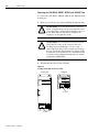
Module Series Designator
To determine the series designator, check the series field on the Allen-
Bradley label attached to your system, axis, and shunt modules. The
series designator is located as shown in the example below.
Figure P.1
Allen-Bradley Label
For: Read This Document: Document Number:
A description and specifications for the 1394 family 1394 Digital, AC, Multi-Axis Motion Control
System Product Data
1394-2.0
A description and specifications for the 1326A Torque Plus
Motors used with the 1394
1326AB 460V, Torque Plus Series, AC Servo
Motors Product Data
1326A-2.9
A description and specifications for the 1326A Rare Earth
Motors used with the 1394
1326AS Series 460V, Low Inertia, Brushless
Servo Motors Product Data
1326A-2.10
Product information regarding cables used with the 1326AB and
1326AS motors
1326 Cables for 460V AC Servo Motors 1326A-2.11
A user guide for GML
programming to be used with the 1394
GMC System.
GML Commander Reference Manual GMLC-5.2
An overview of the Flex I/O
products Flex I/O Product Profile 1794-1.14
Specifications for the Flex I/O products Flex I/O Product Data 1794-2.1
An overview of the PanelView
550/600 product PanelView 550/600 Product Profile 2711-1.13
An overview of the 9/Series products 9/Series CNC Product Profile 8520-1.3
A manual that provides you information on RIO communications Installation Guidelines for the Twinaxial Cable 92-D1770-BCO
A manual that assists you with integrating and maintaining the
9/Series to be used with the 1394 CNC Interface System
9/Series Integration and Maintenance Manual 8520-6.2
An article on wire sizes and types for grounding electrical
equipment
National Electrical Code Published by the National Fire
Protection Association of Boston, MA.
A glossary of industrial automation terms and abbreviations Allen-Bradley Industrial Automation Glossary AG-7.1
1394 Digital Servo Controller
300W Shunt Module
BULLETIN 1394 300W SHUNT MODULE
ALLEN-BRADLEY
FOR USE WITH 1394-SJT22-X SYSTEM MODULE
CAT. PART SER.
INPUT DC INPUT AC
FOR FUSE REPLACEMENT USE:
BUSSMAN CAT. NO.
R
BULLETIN 1394 300W SHUNT MODULE
BULLETIN 1394 300W SHUNT MODULE
ALLEN-BRADLEY
ALLEN-BRADLEY
FOR USE WITH 1394-SJT22-X SYSTEM MODULE
CAT.
CAT.
PART
PART
SER.
SER.
INPUT DC
INPUT DC
INPUT AC
INPUT AC
FOR FUSE REPLACEMENT USE:
FOR FUSE REPLACEMENT USE:
BUSSMAN CAT. NO.
BUSSMAN CAT. NO.
R
Series Field
Shunt Module Example

Publication 1394-5.0 — May 2000
P-4 Preface
1394 Product Receiving and
Storage Responsibility
You, the customer, are responsible for thoroughly inspecting the
equipment before accepting the shipment from the freight company.
Check the item(s) you receive against your purchase order. If any
items are obviously damaged, it is your responsibility to refuse
delivery until the freight agent has noted the damage on the freight
bill. Should you discover any concealed damage during unpacking,
you are responsible for notifying the freight agent. Leave the shipping
container intact and request that the freight agent make a visual
inspection of the equipment.
Leave the product in its shipping container prior to installation. If you
are not going to use the equipment for a period of time, store it:
• in a clean, dry location
• within an ambient temperature range of 0 to 65° C (32 to 149° F)
• within a relative humidity range of 5% to 95%, non-condensing
• in an area where it cannot be exposed to a corrosive atmosphere
• in a non-construction area
Allen-Bradley Support
Allen-Bradley offers support services worldwide, with over 75 Sales/
Support Offices, 512 authorized Distributors and 260 authorized
Systems Integrators located throughout the United States alone, plus
Allen-Bradley representatives in every major country in the world.
Local Product Support
Contact your local Allen-Bradley representative for:
• sales and order support
• product technical training
• warranty support
• support service agreements
Technical Product Assistance
If you need to contact Allen-Bradley for technical assistance, please
review the information in the Troubleshooting chapter first. Then call
your local Allen-Bradley representative. For the quickest possible
response, please have the catalog numbers of your products available
when you call.

Publication 1394-5.0 — May 2000
Chapter
1
Overview
The 1394 System
The 1394 is a modular, multi-axis motion control and drive system
family. Its unique design allows the 1394 to be used as an integrated
motion controller and drive system (GMC) with Turbo or standard
IMC S Class Compact functionality, an integrated 9/440 CNC
system, a 9/Series CNC digital interface drive system, a SERCOS
servo drive system, or an analog servo drive system.
All 1394 systems provide direct line connection (transformerless) for
360 and 480V three-phase input power, efficient IGBT power
conversion, and slide-and-lock, module-to-module connection
systems. Each system module can be configured with up to four axis
modules, with each axis module interfacing to a motor. The 1394
provides significant panel space and interconnect savings.
Series Note
Series C system modules (catalog numbers 1394C-SJTxx-x) and axis
modules (catalog numbers 1394C-AMxx and -AMxx-IH) include
features not available on Series A and B modules (catalog numbers
1394-SJTxx-x and 1394-AMxx).
Series C system modules are interchangeable with Series A and B.
Likewise, Series A, B, and C axis modules are interchangeable with
each other.
Series C is recommended for all new applications. See the tables
above for feature availability. For help in determining the series of
your module(s), refer to the section Module Series Designator in the
Preface.
System Module Features:
Feature Availability
Series C Series A and B
Connector (plug-in) input power termination
Yes No
Cable Clamp (strain relief, shield bond)
Yes No
EMI filter (24V input power, registration)
Yes No
Smart Power (Soft Start, power monitor)
Yes 22 kW systems only
Axis Module Features:
Feature Availability
Series C Series A and B
Cable Clamp (strain relief, shield bond)
Yes No
EMI filter (motor brake and thermal circuit)
Yes No

Publication 1394-5.0 — May 2000
1-2 Overview
Safety Precautions
The following general precautions apply to the 1394:
!
ATTENTION: Only those familiar with the 1394
Digital, AC, Multi-Axis Motion Control System and
associated machinery should plan or implement the
installation, startup, and subsequent maintenance of
the system. Failure to comply can result in personal
injury and/or equipment damage.
ATTENTION: This product contains stored energy
devices. To avoid hazard of electrical shock, wait five
minutes after removing power or verify that all voltage
on the capacitors has been discharged before
attempting to service, repair, or remove this unit. You
should only attempt the procedures in this manual if
you are qualified to do so and familiar with solid-state
control equipment and the safety procedures in
publication NFPA 70E.
ATTENTION: The system integrator is responsible
for local safety and electrical codes.
!
ATTENTION: An incorrectly applied or installed
drive can result in component damage or a reduction
in product life. Wiring or application errors, such as
undersizing the motor, incorrect or inadequate AC
supply, or excessive ambient temperatures can result
in malfunction of the drive.
ATTENTION: This drive contains ESD
(Electrostatic Discharge) sensitive parts and
assemblies. Static control precautions are required
when installing, testing, servicing, or repairing this
assembly. Component damage can result if ESD
control procedures are not followed. If you are not
familiar with static control procedures, refer to Allen-
Bradley publication 8000-4.5.2, Guarding Against
Electrostatic Damage or any other applicable ESD
Protection Handbook.

Publication 1394-5.0 — May 2000
Overview 1-3
1394 System Overview
GMC System
The 1394 GMC System provides all the functionality of the IMC S
Class Compact Motion Controller and power conversion within the
1394 system module. Allen-Bradley offers two versions of the 1394
GMC system module (Standard GMC and GMC Turbo). Both
systems are completely programmed and commissioned using
GML (Graphical Motion Control Language), offer Allen-Bradley
DH485, RS-232, and RS-422 as standard communications, and have
Remote I/O and AxisLink available as communication options.
The 1394x-SJTxx-C (Standard GMC) system supports four axis
modules and provides four channels of auxiliary encoder input. The
1394C-SJTxx-L (Standard GMC) provides the same functionality of
the 1394x-SJTxx-C, but supports only one axis module and provides
two channels of auxiliary encoder input.
In addition, the 1394x-SJTxx-T (GMC Turbo) provides more GML
application program memory and executes the programs faster. The
1394x-SJTxx-T offers 64K of memory with a 32-bit processor while
the 1394x-SJTxx-C offers 32K of program memory with a 16-bit
processor. The 1394x-SJTxx-T also includes a direct, high speed link
to the SLC 5/03, 5/04, or 5/05 that simplifies the programming
required to transfer data between the 1394x-SJTxx-T and the SLC.
Figure 1.1
Two GMC Turbo Systems (1394
x
-SJT
xx
-T)
RIO
DH-485
AxisLink
GML
1326AB and 1326AS Motors
1326AB and 1326AS Motors
Flex I/O
ALEC
845H
Encoder
RS-232/-422
SLC 500
SLC 5/03, 5/04, or 5/05
1
1394
x
-SJT
xx
-T
1394
x
-SJT
xx
-T
PanelView 550
This interface is only available with the 1394
x
-SJT
xx
-T system module.
1
TM
1746-C7 or -C9
1
Flex I/O
Discrete Outputs
Discrete Inputs
Analog Outputs
Analog Inputs
AEC
AEC
Reset
Axis 0 Axis 1
A
B
A
B
Ax
is
1
Ax
is
0
2
1
SSIControl
ConfigurationConfiguration
Switches Switches
Encoder EncoderPower
SSI Control
AB
10
9
8
7
6
2
5
4
3
1
8
7
6
2
4
3
1
5
AB
10
9
8
7
6
2
5
4
3
1
8
7
6
2
4
3
1
5
4100-AEC
842A
Encoder
AxisLink
DANGER
RISK OF ELECTRICAL SHOCK. HIGH VOLTAGE MAY
EXIST UP TO FIVE MINUTES AFTER REMOVING POWER.
DANGER
RISK OF ELECTRICAL SHOCK. HIGH VOLTAGE MAY
EXIST UP TO FIVE MINUTES AFTER REMOVING POWER.

Publication 1394-5.0 — May 2000
1-4 Overview
Figure 1.2
Two Standard GMC Systems (1394
x
-SJT
xx
-C and 1394C-SJT-
xx
-L)
RIO
PanelView 550
DH-485
AxisLink
GML
1326AB and 1326AS Motors
1326AB or 1326AS Motor
Flex I/O
ALEC
845H
Encoder
RS-232/-422
SLC 500
845H Encoder
1394C-SJT
xx
-L
1394
x
-SJT
xx
-C
Flex I/O
Discrete Outputs
Discrete Inputs
Analog Outputs
Analog Inputs
AEC
AEC
Reset
Axis 0 Axis 1
A
B
A
B
Ax
is
1
Ax
is
0
2
1
SSIControl
ConfigurationConfiguration
Switches Switches
Encoder EncoderPower
SSI Control
AB
10
9
8
7
6
2
5
4
3
1
8
7
6
2
4
3
1
5
AB
10
9
8
7
6
2
5
4
3
1
8
7
6
2
4
3
1
5
4100-AEC
842A
Encoder
AxisLink
DANGER
RISK OF ELECTRICAL SHOCK. HIGH VOLTAGE MAY
EXIST UP TO FIVE MINUTES AFTER REMOVING POWER.
DANGER
RISK OF ELECTRICAL SHOCK. HIGH VOLTAGE MAY
EXIST UP TO FIVE MINUTES AFTER REMOVING POWER.

Publication 1394-5.0 — May 2000
Overview 1-5
CNC Interface System
The 1394 9/Series CNC Interface system (1394-SJTxx-E) provides a
digital servo system to be used with the 9/260 and 9/290 CNC. This
system provides all power electronics and uses a cost-saving digital
interface approach. Servo control for this system is handled by the 9/
Series CNC. A fiber optic I/O ring is provided to the 1394 and the
system is completely interfaced with and programmed using ODS
(Off-Line Development System) and the CNC operator panel. Allen-
Bradley Remote I/O, MMS/Ethernet (9/260 and 9/290 only), and
Data Highway Plus (9/260 and 9/290 only) communications are
available options with the 9/Series CNC interface system.
Figure 1.3
CNC Interface System
1326AB Motors
1394
1746 I/O
9/230, 9/260, or
9/290 CNC
RIO
PLC
Operator Panel
Fiber Optic Ring
Fiber Optic Ring
Fiber Optic Ring
Fiber Optic Ring
ODS Software
MTB Panel
R

Publication 1394-5.0 — May 2000
1-6 Overview
SERCOS System
The 1394 SERCOS system module (1394C-SJTxx-D) provides a
digital servo drive system with a fiber-optic digital network interface.
It can be used as a velocity or torque control system and is quickly
commissioned with the Allen-Bradley SERCOS Interface Module
(Bulletin 1756 with 1756-MxxSE), which provides access to auto
tuning and start-up prompting. The 1394 also provides a SCANport
interface as a standard feature.
For specific installation and wiring information refer to the 1394
SERCOS Multi-Axis Motion Control System User Manual
(publication 1394-5.20).
Figure 1.4
SERCOS System
1394 SERCOS System
ControlLogix Chassis
1326AB, 1326AS, and MP Series Motors
SERCOS
DANGER
RISK OF ELECTRICAL SHOCK. HIGH VOLTAGE MAY
EXIST UP TO FIVE MINUTES AFTER REMOVING POWER.
1326AB, 1326AS, and MP Series Motors
DANGER
RISK OF ELECTRICAL SHOCK. HIGH VOLTAGE MAY
EXIST UP TO FIVE MINUTES AFTER REMOVING POWER.
SERCOS
SERCOS
1394 SERCOS System
1756-M
xx
SE Interface
SERCOS System Module
SERCOS System Module
Page is loading ...
Page is loading ...
Page is loading ...
Page is loading ...
Page is loading ...
Page is loading ...
Page is loading ...
Page is loading ...
Page is loading ...
Page is loading ...
Page is loading ...
Page is loading ...
Page is loading ...
Page is loading ...
Page is loading ...
Page is loading ...
Page is loading ...
Page is loading ...
Page is loading ...
Page is loading ...
Page is loading ...
Page is loading ...
Page is loading ...
Page is loading ...
Page is loading ...
Page is loading ...
Page is loading ...
Page is loading ...
Page is loading ...
Page is loading ...
Page is loading ...
Page is loading ...
Page is loading ...
Page is loading ...
Page is loading ...
Page is loading ...
Page is loading ...
Page is loading ...
Page is loading ...
Page is loading ...
Page is loading ...
Page is loading ...
Page is loading ...
Page is loading ...
Page is loading ...
Page is loading ...
Page is loading ...
Page is loading ...
Page is loading ...
Page is loading ...
Page is loading ...
Page is loading ...
Page is loading ...
Page is loading ...
Page is loading ...
Page is loading ...
Page is loading ...
Page is loading ...
Page is loading ...
Page is loading ...
Page is loading ...
Page is loading ...
Page is loading ...
Page is loading ...
Page is loading ...
Page is loading ...
Page is loading ...
Page is loading ...
Page is loading ...
Page is loading ...
Page is loading ...
Page is loading ...
Page is loading ...
Page is loading ...
Page is loading ...
Page is loading ...
Page is loading ...
Page is loading ...
Page is loading ...
Page is loading ...
Page is loading ...
Page is loading ...
Page is loading ...
Page is loading ...
Page is loading ...
Page is loading ...
Page is loading ...
Page is loading ...
Page is loading ...
Page is loading ...
Page is loading ...
Page is loading ...
Page is loading ...
Page is loading ...
Page is loading ...
Page is loading ...
Page is loading ...
Page is loading ...
Page is loading ...
Page is loading ...
Page is loading ...
Page is loading ...
Page is loading ...
Page is loading ...
Page is loading ...
Page is loading ...
Page is loading ...
Page is loading ...
Page is loading ...
Page is loading ...
Page is loading ...
Page is loading ...
Page is loading ...
Page is loading ...
Page is loading ...
Page is loading ...
Page is loading ...
Page is loading ...
Page is loading ...
Page is loading ...
Page is loading ...
Page is loading ...
Page is loading ...
Page is loading ...
Page is loading ...
Page is loading ...
Page is loading ...
Page is loading ...
Page is loading ...
Page is loading ...
Page is loading ...
Page is loading ...
Page is loading ...
Page is loading ...
Page is loading ...
Page is loading ...
Page is loading ...
Page is loading ...
Page is loading ...
Page is loading ...
Page is loading ...
Page is loading ...
Page is loading ...
Page is loading ...
Page is loading ...
Page is loading ...
Page is loading ...
Page is loading ...
Page is loading ...
Page is loading ...
Page is loading ...
Page is loading ...
Page is loading ...
Page is loading ...
Page is loading ...
Page is loading ...
Page is loading ...
Page is loading ...
Page is loading ...
Page is loading ...
Page is loading ...
Page is loading ...
Page is loading ...
Page is loading ...
Page is loading ...
Page is loading ...
Page is loading ...
Page is loading ...
Page is loading ...
Page is loading ...
Page is loading ...
Page is loading ...
Page is loading ...
Page is loading ...
Page is loading ...
Page is loading ...
Page is loading ...
Page is loading ...
Page is loading ...
Page is loading ...
Page is loading ...
Page is loading ...
Page is loading ...
Page is loading ...
Page is loading ...
Page is loading ...
Page is loading ...
Page is loading ...
Page is loading ...
Page is loading ...
Page is loading ...
Page is loading ...
Page is loading ...
Page is loading ...
Page is loading ...
Page is loading ...
Page is loading ...
Page is loading ...
Page is loading ...
Page is loading ...
Page is loading ...
Page is loading ...
Page is loading ...
Page is loading ...
Page is loading ...
Page is loading ...
Page is loading ...
Page is loading ...
Page is loading ...
Page is loading ...
Page is loading ...
Page is loading ...
Page is loading ...
Page is loading ...
Page is loading ...
Page is loading ...
Page is loading ...
Page is loading ...
Page is loading ...
Page is loading ...
Page is loading ...
Page is loading ...
Page is loading ...
Page is loading ...
Page is loading ...
Page is loading ...
Page is loading ...
Page is loading ...
Page is loading ...
Page is loading ...
Page is loading ...
Page is loading ...
Page is loading ...
Page is loading ...
Page is loading ...
Page is loading ...
Page is loading ...
Page is loading ...
Page is loading ...
Page is loading ...
Page is loading ...
Page is loading ...
Page is loading ...
Page is loading ...
Page is loading ...
Page is loading ...
Page is loading ...
Page is loading ...
Page is loading ...
Page is loading ...
Page is loading ...
Page is loading ...
Page is loading ...
Page is loading ...
Page is loading ...
Page is loading ...
Page is loading ...
Page is loading ...
Page is loading ...
Page is loading ...
Page is loading ...
Page is loading ...
Page is loading ...
Page is loading ...
Page is loading ...
Page is loading ...
Page is loading ...
Page is loading ...
Page is loading ...
Page is loading ...
Page is loading ...
Page is loading ...
Page is loading ...
Page is loading ...
Page is loading ...
Page is loading ...
Page is loading ...
Page is loading ...
Page is loading ...
Page is loading ...
Page is loading ...
-
 1
1
-
 2
2
-
 3
3
-
 4
4
-
 5
5
-
 6
6
-
 7
7
-
 8
8
-
 9
9
-
 10
10
-
 11
11
-
 12
12
-
 13
13
-
 14
14
-
 15
15
-
 16
16
-
 17
17
-
 18
18
-
 19
19
-
 20
20
-
 21
21
-
 22
22
-
 23
23
-
 24
24
-
 25
25
-
 26
26
-
 27
27
-
 28
28
-
 29
29
-
 30
30
-
 31
31
-
 32
32
-
 33
33
-
 34
34
-
 35
35
-
 36
36
-
 37
37
-
 38
38
-
 39
39
-
 40
40
-
 41
41
-
 42
42
-
 43
43
-
 44
44
-
 45
45
-
 46
46
-
 47
47
-
 48
48
-
 49
49
-
 50
50
-
 51
51
-
 52
52
-
 53
53
-
 54
54
-
 55
55
-
 56
56
-
 57
57
-
 58
58
-
 59
59
-
 60
60
-
 61
61
-
 62
62
-
 63
63
-
 64
64
-
 65
65
-
 66
66
-
 67
67
-
 68
68
-
 69
69
-
 70
70
-
 71
71
-
 72
72
-
 73
73
-
 74
74
-
 75
75
-
 76
76
-
 77
77
-
 78
78
-
 79
79
-
 80
80
-
 81
81
-
 82
82
-
 83
83
-
 84
84
-
 85
85
-
 86
86
-
 87
87
-
 88
88
-
 89
89
-
 90
90
-
 91
91
-
 92
92
-
 93
93
-
 94
94
-
 95
95
-
 96
96
-
 97
97
-
 98
98
-
 99
99
-
 100
100
-
 101
101
-
 102
102
-
 103
103
-
 104
104
-
 105
105
-
 106
106
-
 107
107
-
 108
108
-
 109
109
-
 110
110
-
 111
111
-
 112
112
-
 113
113
-
 114
114
-
 115
115
-
 116
116
-
 117
117
-
 118
118
-
 119
119
-
 120
120
-
 121
121
-
 122
122
-
 123
123
-
 124
124
-
 125
125
-
 126
126
-
 127
127
-
 128
128
-
 129
129
-
 130
130
-
 131
131
-
 132
132
-
 133
133
-
 134
134
-
 135
135
-
 136
136
-
 137
137
-
 138
138
-
 139
139
-
 140
140
-
 141
141
-
 142
142
-
 143
143
-
 144
144
-
 145
145
-
 146
146
-
 147
147
-
 148
148
-
 149
149
-
 150
150
-
 151
151
-
 152
152
-
 153
153
-
 154
154
-
 155
155
-
 156
156
-
 157
157
-
 158
158
-
 159
159
-
 160
160
-
 161
161
-
 162
162
-
 163
163
-
 164
164
-
 165
165
-
 166
166
-
 167
167
-
 168
168
-
 169
169
-
 170
170
-
 171
171
-
 172
172
-
 173
173
-
 174
174
-
 175
175
-
 176
176
-
 177
177
-
 178
178
-
 179
179
-
 180
180
-
 181
181
-
 182
182
-
 183
183
-
 184
184
-
 185
185
-
 186
186
-
 187
187
-
 188
188
-
 189
189
-
 190
190
-
 191
191
-
 192
192
-
 193
193
-
 194
194
-
 195
195
-
 196
196
-
 197
197
-
 198
198
-
 199
199
-
 200
200
-
 201
201
-
 202
202
-
 203
203
-
 204
204
-
 205
205
-
 206
206
-
 207
207
-
 208
208
-
 209
209
-
 210
210
-
 211
211
-
 212
212
-
 213
213
-
 214
214
-
 215
215
-
 216
216
-
 217
217
-
 218
218
-
 219
219
-
 220
220
-
 221
221
-
 222
222
-
 223
223
-
 224
224
-
 225
225
-
 226
226
-
 227
227
-
 228
228
-
 229
229
-
 230
230
-
 231
231
-
 232
232
-
 233
233
-
 234
234
-
 235
235
-
 236
236
-
 237
237
-
 238
238
-
 239
239
-
 240
240
-
 241
241
-
 242
242
-
 243
243
-
 244
244
-
 245
245
-
 246
246
-
 247
247
-
 248
248
-
 249
249
-
 250
250
-
 251
251
-
 252
252
-
 253
253
-
 254
254
-
 255
255
-
 256
256
-
 257
257
-
 258
258
-
 259
259
-
 260
260
-
 261
261
-
 262
262
-
 263
263
-
 264
264
-
 265
265
-
 266
266
-
 267
267
-
 268
268
-
 269
269
-
 270
270
-
 271
271
-
 272
272
-
 273
273
-
 274
274
-
 275
275
-
 276
276
-
 277
277
-
 278
278
-
 279
279
-
 280
280
-
 281
281
-
 282
282
-
 283
283
-
 284
284
-
 285
285
-
 286
286
-
 287
287
-
 288
288
-
 289
289
-
 290
290
-
 291
291
-
 292
292
-
 293
293
-
 294
294
-
 295
295
-
 296
296
-
 297
297
-
 298
298
-
 299
299
-
 300
300
-
 301
301


Allen-Bradley 1770-M10 User manual
- Type
- User manual
- This manual is also suitable for
Ask a question and I''ll find the answer in the document
Finding information in a document is now easier with AI
Related papers
-
Allen-Bradley 1394C-SJT22-D Installation guide
-
-
-
-
-
-
-
-
Allen-Bradley FLEX I/O DeviceNet 1794-ADN User manual
-
Other documents
-
Rockville RXC20D Owner's manual
-
VEVOR U140256C Operating instructions
-
 Connector Products (CPI) Tap Connector Installation guide
-
 Baldor-Reliance DC Injection Brake Connection Diagram Owner's manual
-
optonica LED STRIP Installation guide
-
SolaHD FB2 Secondary Block Fusing Block Owner's manual
-
Intelligent Motion Systems IM1007IE User manual
-
 Rockwell Automation Allen-Bradley Kinetix 6000 User manual
-
 Code 3 Matrix Switch Node Install Instructions
-
 Inovance IS580****-**-1 Series User manual


