Page is loading ...

thermaltransfer.com ttp-sales@apiheattransfer.com +1.262.554.8330
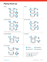
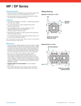
Piping Hook-up
A Series B Series
HC / SSC / EC Series SLE / SL / R Series
EK / EKS / EKM Series K / KN Series
U / UC / UR Series
43
2
1
4
3
21
4
3
21
4
3
21
4
2
1
4
3
21
4
3
2
1
21
4
321
4
3
2
1
3
21
4
321
4
3
213
2 1
4
3
21
4
3
21
4
3
21
4
3
21
Hot Fluid In Cooling Water In
Cooled Fluid Out Cooling Water Out
4
3
2
1
*Note: For all two pass and four pass heat exchangers:
connections and may be reversed, and
connections and may be reversed
with no effect on performance.
4
3
21
EC bonnet rotation is slightly different from what is shown. See Series literature for details.
Note baffle location when inserting bundle into shell assembly after cleaning.
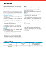
0916

thermaltransfer.com ttp-sales@apiheattransfer.com +1.262.554.8330
Shell & Tube Recommendations
Installation
The satisfactory use of this heat exchange equipment is dependent upon
precautions which must be taken at the time of the installation.
1. Connect and circulate the hot fluid in the shell side (over small tubes)
and the cooling water in the tube side (inside small tubes). Note piping
diagrams.
2. If an automatic water regulating valve is used, place it on the INLET
connection of the cooler. Arrange the water outlet piping so that the
exchanger remains flooded with water, but at little or no pressure.
The temperature probe is placed in the hydraulic reservoir to sense a
system temperature rise. Write the factory for water regulating valve
recommendations.
3. There are normally no restrictions as to how this cooler may be mounted.
The only limitation regarding the mounting of this equipment is the
possibility of having to drain either the water or the oil chambers after the
cooler has been installed. Both fluid drain plugs should be located on the
bottom of the cooler to accomplish the draining of the fluids. Drains are
on most models.
4. It is possible to protect your cooler from high flow and pressure surges of
hot fluid by installing a fast-acting relief valve in the inlet line to the cooler.
5. It is recommended that water strainers be installed ahead of this cooler
when the source of cooling water is from other than a municipal water
supply. Dirt and debris can plug the water passages very quickly,
rendering the cooler ineffective. Write the factory for water strainer
recommendations.
6. Fixed bundle heat exchangers are generally not recommended for steam
service. For steam applications, a floating bundle exchanger is required.
Note: When installing floating bundle unit, secure one end firmly and
opposite end loosely to allow bundle to expand and contract. Consult
factory for selection assistance.
7. Piping must be properly supported to prevent excess strain on the heat
exchanger ports. If excessive vibration is present, the use of shock
absorbing mounts and flexible connectors is recommended.
Service
Each heat exchanger has been cleaned at the factory and should not require
further treatment. It may be well to inspect the unit to be sure that dirt or
foreign matter has not entered the unit during shipment. The heat exchanger
should be mounted firmly in place with pipe connections tight.
Caution
If sealant tape is used on pipe threads, the degree of resistance between
mating parts is less, and there is a greater chance for cracking the heat
exchanger castings. Do not overtighten. When storing the unit, be sure to
keep the oil and water ports sealed. If storage continues into cold winter
months, the water chamber must be drained to prevent damage by freezing.
Performance information should be noted and recorded on newly installed
units so that any reduction in effectiveness can be detected. Any loss in
efficiency can normally be traced to an accumulation of oil sludge, or
water scale.
Recommendations
Replace gaskets when removing end castings. It is recommended that
gaskets be soaked in oil to prevent corrosion and ensure a tight seal.
Salt water should not be used in standard models. Use salt water in special
models having 90/10 copper-nickel tubes, tube sheets*, bronze bonnets and
zinc anodes on the tube side. Brackish water or other corrosive fluids may
require special materials of construction.
When zinc anodes are used for a particular application, they should be
inspected two weeks after initial startup.
At this time, by visual inspection of the anode, determination of future
inspection intervals can be made, based on the actual corrosion rate of
the zinc metal.
The zinc anodes must be replaced when 70% of the zinc volume has
been consumed.
It may be necessary to drain the water chambers of the exchanger to protect
it from damage by freezing temperatures. Drains are provided in most
standard models.
The oil chamber of the exchanger may become filled with sludge
accumulation and require cleaning. It is recommended that the unit be
flooded with a commercial solvent and left to soak for one-half hour.
Backflowing with the solvent or regular oil will remove most sludge.
Repeated soaking and backflowing may be required, depending on the
degree of sludge buildup.
It may be necessary to clean the inside of the cooling tubes to remove any
contamination and/or scale buildup. It is recommended that a fifty-fifty
percent solution of inhibited muriatic acid and water may be used. For severe
problems, the use of a brush through the tubes may be of some help. Be
sure to use a soft bristled brush to prevent scouring the tube surface causing
accelerated corrosion. Upon completion of cleaning, be certain that all
chemicals are removed from the shellside and the tubeside before the heat
exchanger is placed into service.
When ordering replacement parts or making an inquiry regarding service,
mention model number, serial number, and the original purchase order number.
*Available on HC/SSC/SSCA Series models only.
0916

thermaltransfer.com ttp-sales@apiheattransfer.com +1.262.554.8330
Maximum Shell & Tube Flow Rates
B Series Model No. Example: B-702-A4-F
Unit Size
Shell Side (GPM) / Baffle Spacing Tube Side (GPM)
A B C D E 0 T T
400 9.6 — — — — 25
700 17 29 29 — — 61 31 15
1000 24 48 69 69 — 146 73 37
1200 29 57 115 115 — 224 112 56
1600 37 75 149 253 — 363 181 91
2000 — — 187 347* 457* 652 326 163
*281 GPM maximum for all B-2005-D **500 GPM maximum for all B-20080-E and 562 GPM maximum for all B2006-E6 or B-2006-E10
562 GPM maximum for all B-2006-E6 or B-2006-E10
CAUTION
Incorrect installation can cause this product to fail prematurely, causing the
shell side and tube side fluids to intermix. Maximum allowable flow rates are
as charted below.
K / EK Series Model No. Example: EK or K-712-F
Unit Size Shell Side (GPM)
Tube Side (GPM)
0 T
500 20 13 —
100 70 24 12
1000 100 56 28
HC / SSC Series Model No. Example: HC-1024-2-6-F
Unit Size Baffle Size Shell Side (GPM)
Tube Side (GPM)
0 T F
600
1.38 19
48 24 122 29
3 29
800
1.38 26
84 42 21
1.7 31
2 38
3 57
4 69
1000
1.38 24
146 23 37
2 41
3 64
5 69
1200
2.5 60
224 112 56
3 77
3.62 93
5 115
6 115
1700
3. 125
465 232 116
4 143
4.5 161
5 179
6 215
7 251
8.4 253
EC Series Model No. Example: EC-1236-6-F
Unit Size Baffle Size Shell Side (GPM)
Tube Side (GPM)
0 T F
1000
4 55
66 33 15
6 70
8 70
1200
4 65
120 60 28
6 100
8 115
12 115
1700
4 90
220 110 52
6 140
8 190
12 255
A Series Model No. Example: A-1024-2-6-F
Unit Size Baffle Spacing Shell Side (GPM)
Tube Side (GPM)
0 T F
SA-400 .75 7 18 — —
2 19
600
1 14
48 24 12
1.5 21
2 29
4 29
800
1.5 29
87 43 21
2 38
3 57
4 69
1000
1.5 32
146 73 37
2 42
3 60
4 69
1200
2 51
224 112 56
3 77
4 103
6 115
1600
26 66
280 203 101
3 100
4 133
6 200
0916
/