Page is loading ...

thermaltransfer.com ttp-sales@apiheattransfer.com +1.262.554.8330
General Information
Depending on material combinations, pressure ratings and functions, there are
several different types of compact Brazed Plate Heat Exchangers (BPHEs). The
standard materials are stainless steel, vacuum-brazed with a pure copper or
nickel-based filler.
The basic materials of construction indicate the type of fluids that TTP’s BPHEs
can be used with. Typical examples are: synthetic or mineral oil, organic
solvents, water (not seawater), glycol mixtures (ethylene and propylene glycol).
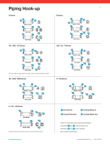
The front plate of TTP’s BPHE is marked with an arrow. The
purpose of this marker is to indicate the front side of the BPHE
and the location of the inner and outer circuits/channels. With
the arrow pointing up, the left side (Port F1, F3) is the inner
circuit and the right side (Port F2, F4) is the outer circuit. For
TTP asymmetric products one circuit is narrow while the other
is wide, which makes it additionally important to correctly
combine flow and circuit to reach design performance.
Ports F1/F2/F3/F4 are situated on the front of the heat
exchanger.
Design Conditions
The standard pressure rating used for TTP BPHEs, i.e. for standard operating
pressure, is maximum 450 PSI (3.1 MPa). TTP offers a wide range of pressure
ratings based on applications, from low pressures (116 PSI) up to high pressures
(2030 PSI). TTP’s standard maximum operating temperature is 437°F for
copper-brazed BPHEs, and 660°F for Nickel brazed BPHEs. However, as
temperature and pressure are closely coupled, there is a possibility to increase
the pressure if the temperature is reduced. For details, please check the label
and other technical documentation.
Mounting
Never expose the unit to pulsations or excessive cyclic pressure or temperature
changes. It is also important that no vibrations are transferred to the heat
exchanger. If there is a risk of this, install vibration absorbers. For large
connection diameters, we advise you to use an expanding device in the pipeline.
It is also suggested that e.g. a rubber mounting strip should be used as a buffer
between the BPHE and the mounting clamp.
In single-phase applications, e.g. water-to-water or water-to-oil, the mounting
direction has little or no effect on the performance of the heat exchanger.
Connections
Allowable Connection Loads for Pipe Assembly Conditions
The maximum allowable connection loads
given below are valid for low cycle fatigue.
If high cycle fatigue is involved special
analysis should be made.
Allowable connection loads for different pipe assembly conditions:
Pipe Size
Shear
Force, Fs
(lbf)
Tension
Force, Ft
(lbf)
Bending
Moment, Mb
(lbf* in)
Torque, Mt
(lbf* in)
½" 787 562 177 310
¾" 2698 562 177 1018
1" 2518 899 398 1372
1¼" 3260 1461 774 2345
1½" 3709 2136 1372 3098
2" 4833 3035 2257 5310
2½" 10004 4047 3452 12834
3" 12447 4136 5089 21773
Allowable Loads for Stud Bolt Assembly Conditions
Mounting stud bolts, in different versions and locations, are
available on the BPHEs as an option. These stud bolts are welded
to the unit. The maximum allowable load on the stud bolts during
assembly are stated below.
Allowable loads for different stud bolt assembly conditions:
Stud Bolt
Stress Area
As (in2)
Tension Force
Ft (lbf)
Torque
Mt (lbfin)
M6 0.032 315 27
M8 0.053 585 71
M12 0.144 1349 239
Installation of BPHEs in Different Applications
Single-Phase Applications
Normally, the circuit with the highest temperature
and/or pressure should be connected on the left side
of the heat exchanger when the arrow is pointing
upwards. For example, in a typical water-to-water
application, the two fluids are connected in a counter-
current flow, i.e. the hot water inlet in connection
F1, outlet F3, cold water inlet F4, outlet F2. This is
because the right-hand side of the heat exchanger
contains one channel more than the left-hand side,
and the hot medium is thus surrounded by the cold
medium to prevent heat loss.
Water Strainer
A water strainer should be installed in the water inlet to protect the unit from
particulate matter. 16-20 mesh minimum (20-40 mesh best choice).
Piping
Piping must be properly supported to prevent excess strain on the heat
exchanger ports. Stainless steel is typically not satisfactory for salt
water service.
Cleaning
In some applications, the fouling tendency could be very high; for example
when using extremely hard water. It is always possible to clean the exchanger
by circulating a cleaning liquid. Use a tank with a weak acid. 5% phosphoric
acid, or if the exchanger is frequently cleaned, 5% oxalic acid. Pump the
cleaning liquid through the exchanger. For optimum cleaning, the cleaning
solution flow rate should be a minimum of 1.5 times normal flow rate,
preferably in a backflush mode. Afterwards rinse with large amounts of fresh
water in order to get rid of all the acid before starting up the system again.
Clean at regular intervals.
Storage
BPHEs are to be stored dry. The temperature should not be below 34°F and not
over 122°F for long term storage (more than 2 weeks).
Disclaimer
TTP’s BPHE performance is based on installation, maintenance and operating
conditions done in conformance with these instructions. TTP cannot assume
any liability for BPHEs that do not meet these criteria.
The heat exchanger is not type-approved for fatigue loading.
F2
F1
F3
F4
Mt
Mb
F2
F1
F3
F4
Mt
Mb
F2
F1
F3
F4
F2
F1
F3
F4
Mt
Mb
F2
F1
F3
F4
Mt
Mb
BPSW / BPW Series 0916
/