Page is loading ...

thermaltransfer.com ttp-sales@apiheattransfer.com +1.262.554.8330
AO / AOVH / AOHM / AOVHM / AOF Series
General Information
1. Air cooled oil coolers are built for operation with maximum oil pressures of
300 PSI and temperatures of 400°F.
2. The motors furnished are specially built for fan duty. They are guaranteed
by the manufacturer for operation in a maximum ambient temperature of
104°F. Consideration should be given to installation location so motors are
not subjected to temperatures above this level.
3. Air/oil coolers that are to be installed for utilization of waste heat for the
space heating should be mounted 7 to 14 feet above the floor depending
on the structure, for proper heat distribution.
Installation
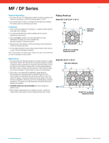
1. “AO” and “AOF” coolers are designed for suspension by eye bolts or
threaded hangar rods screwed into the upper and lower covers in 1/2"-13
threaded holes; “AOVH” coolers have 6 to 12 holes (0.56" diameter) in the
base for mounting. Refer to product page for location and quantity.
2. Units should not be located in corrosive atmospheres as rapid deterioration
of casing, cooling coil, fan and motor may take place resulting in reduced life.
3. For proper air flow, a minimum of 12" should be allowed between the oil
cooler fan and any walls or obstructions.
4. Piping should be sized based on oil flow and pressure drop requirements
and not on the oil coolers supply and return connection size. Piping should
also be properly supported to prevent excessive strain to connection,
manifolds, etc.
5. Filter located ahead of the cooler should be installed to trap scale, dirt
or sludge that may be present in piping and equipment, or that may
accumulate with use. A thermostatic or spring loaded by-pass relief valve
installed ahead of the cooler may be helpful to speed warm-up and relieve
the system of excessive pressure. All accessories should be considered in
the original heat rejection and piping calculations.
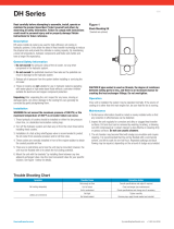
6. Electric Motors: CAUTION To prevent possible electrical shock, it is
important to make sure this unit is grounded properly. Connect motor
only to a power supply of the same characteristics as shown on the
motor nameplate. Voltage may vary 10% of nameplate voltage. Be sure
to provide proper fusing to prevent possible motor burnout. Follow wiring
diagram printed on motor nameplate or in terminal box. Before starting
motor, follow motor manufacturer recommendations. Turn fan manually
to eliminate possible motor burn out in the event the fan has become
damaged in shipment. Observe operation carefully after motor is started
for the first time.
7. Hydraulic Motors: Connect motor, port B, to inlet oil line and return line to
port A for correct rotation. A filter is highly recommended upstream of the
motor rated at 25 micron nominal. Controlling oil flow rate as specified on
motor data sheet with cooler is very important. Maximum oil pressure to
motor is 2000 PSI, minimum pressure is shown on motor data sheet. Do
not allow dirty oil to enter the motor. Excessive flows will cause fan blade
failure. Insufficient flows to motor will reduce cooling capacity.
Maintenance
Inspect the unit regularly for loose bolts and connections, rust and corrosion,
and dirty or clogged heat transfer surfaces (cooling coil).
Heat Transfer Surface
Dirt and dust should be removed by brushing the fins and tubes and blowing
loose dirt off with an air hose. Should the surface be greasy, the motor should
be removed and the fins and tubes brushed or sprayed with a mild alkaline
solution, or a non-flammable degreasing fluid. Follow with a hot water rinse
and dry thoroughly. A steam hose may also be used effectively.
Casing, Fan and Motor: Dirt and grease should be removed from these parts.
Rusty or corroded surfaces should be sanded clean and repainted.
Internal Cleaning
At lease once a year piping should be disconnected and a degreasing agent
or flushing oil circulated through the unit to remove sludge from turbulators
and internal tube surfaces to return the unit to full capacity. A thorough
cleaning of the entire system in the same manner is preferable to avoid
carry-over from uncleaned piping, pump and accessories. The strainer
of any filtering devices should be removed and serviced following this
cleaning operation.
Electric Motor
Keep outside surface free of dirt and grease so motor will cool properly.
Make sure cooling air over motor is not obstructed. Prelubricated ball bearing
motors are normally furnished and require no grease for about 5 to 10 years.
Sleeve bearing motors require oil after three years.
Hydraulic Motor
Change any oil filter(s) in the motor circuit as frequently as necessary to
assure that good, clean oil is maintained.
Units with Replaceable Air Filters
Examine filters for dirt and grease accumulation twice yearly, or more
if operating conditions dictate. If disposable filters are used, replace as
required. If the washable aluminum filters are used, wash with a warm water
and soap solution that will remove dirt and cut grease build-up. Make sure
that the aluminum filter is completely dry before replacing the unit. This filter
can be made more effective if treated with a lightweight oil before placing in
service. It is recommended that a spare aluminum filter be kept in stock to
minimize downtime during the filter cleaning operation.
Repair or Replacement of Parts
When ordering replacement parts or making inquiry regarding service,
mention model number, serial number and the original purchase order
number. Any reference to the motor must carry full nameplate data.
0916

thermaltransfer.com ttp-sales@apiheattransfer.com +1.262.554.8330
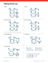
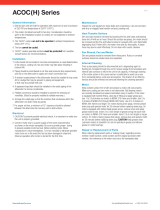
One Pass Two Pass
Air / Oil Heat Exchangers
AO, AOF & AOHM
Models
One Pass Flow
(GPM)
AOVH & AOVHM
Models
One Pass Flow
(GPM)
5 2-80 5 4-160
10 3-80 10 6-160
15 4-80 15 8-160
20 5-80 20 10-160
25 6-100 25 12-200
30 7-100 30 14-200
35 8-112 35 16-220
40 9-118 40 18-230
Model
Maximum Fan Speed
(GPM)
Oil Flow Required
(GMP)
Displacement
(cu. in./rev)
Minimum Operating Pressure
(PSI)
AOHM-5 1725 1.6 .22 300
AOHM-10 1725 1.6 .22 300
AOHM-15 1725 1.6 .22 300
AOHM-20 1725 1.6 .22 300
AOHM-25 1140 1.1 .22 400
AOHM-30 1140 1.1 .22 400
AOHM-35 1140 1.1 .22 900
AOHM-40 1140 1.1 .22 900
AOVHM-5 3450 3.3 .22 300
AOVHM-10 3450 3.3 .22 300
AOVHM-15 3450 3.3 .22 300
AOVHM-20 3450 3.3 .22 300
AOVHM-25 1725 3.4 .45 500
AOVHM-30 1725 3.4 .45 500
AOVHM-35 1725 5.2 .70 1000
AOVHM-40 1725 5.2 .70 1000
Maximum operating pressure 2000 PSI. Stated minimum operating pressure is at inlet port of motor. 1000 PSI allowable downstream back pressure.
AO, AOF & AOHM
Models
Two Pass Flow
(GPM)
AOVH & AOVHM
Models
Two Pass Flow
(GPM)
5 2-25 5 4-50
10 2-30 10 4-60
15 2-30 15 4-60
20 2-40 20 4-80
25 2-40 25 4-80
30 2-40 30 4-80
35 3-40 35 6-80
40 4-40 40 8-80
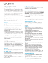
Oil
IN
Oil
OUT
Cap
Oil
OUT
Oil
IN
Gresen Hydraulic Motor Specifications
0916
/