Page is loading ...

thermaltransfer.com ttp-sales@apiheattransfer.com +1.262.554.8330
At this time, by visual inspection of the anode, determination of future
inspection intervals can be made, based on the actual corrosion rate of the
zinc metal.
The zinc anodes must be replaced when 70% of the zinc volume has been
consumed.
It may be necessary to drain the water chambers of the exchanger to protect it
from damage by freezing temperatures. Drains are provided in most standard
models.
The oil chamber of the exchanger may become filled with sludge
accumulation and require cleaning. It is recommended that the unit be
flooded with a commercial solvent and left to soak for one-half hour.
Backflowing with the solvent or regular oil will remove most sludge. Repeated
soaking and backflowing may be required, depending on the degree of
sludge buildup.
It may be necessary to clean the inside of the cooling tubes to remove any
contamination and/or scale buildup. It is recommended that a 50/50 percent
solution of inhibited muriatic acid and water may be used. For severe problems,
the use of a brush through the tubes may be of some help. Be sure to use a
soft bristled brush to prevent scouring the tube surface causing accelerated
corrosion. Upon completion of cleaning, be certain that all chemicals are
removed from the shellside and the tubeside before the heat exchanger is
placed into service.
When ordering replacement parts or making an inquiry regarding service,
mention model number, serial number, and the original purchase order number.
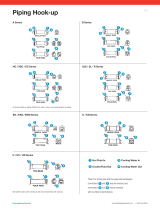
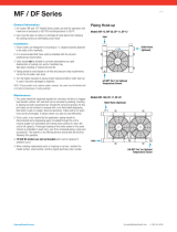
Piping Hook-up
CORE ASSEMBLY/ MOTOR SERVICE
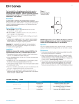
Installation
The satisfactory use of this heat exchange equipment
is dependent upon precautions which must be taken at the time of
the installation.
1. Connect and circulate the hot fluid in the shell side (over small tubes) and the
cooling water in the tube side (inside small tubes). Note piping diagrams.
2. If an automatic water regulating valve is used, place it on the INLET
connection of the cooler. Arrange the water outlet piping so that the
exchanger remains flooded with water, but at little or no pressure.
The temperature probe is placed in the hydraulic reservoir to sense a
system temperature rise. Write the factory for water regulating valve
recommendations.
3. There are normally no restrictions as to how this cooler may be mounted.
The only limitation regarding the mounting of this equipment is the
possibility of having to drain either the water or the oil chambers after the
cooler has been installed. Both fluid drain plugs should be located on the
bottom of the cooler to accomplish the draining of the fluids. Drains are
on most models.
4. It is possible to protect your cooler from high flow and pressure surges of
hot fluid by installing a fast-acting relief valve in the inlet line to the cooler.
5. It is recommended that water strainers be installed ahead of this cooler
when the source of cooling water is from other than a municipal water
supply. Dirt and debris can plug the water passages very quickly, rendering
the cooler ineffective. Write the factory for water strainer recommendations.
6. Fixed bundle heat exchangers are generally not recommended for steam
service. For steam applications, a floating bundle exchanger is required.
Note: When installing floating bundle unit, secure one end firmly and
opposite end loosely to allow bundle to expand and contract. Consult
factory for selection assistance.
7. Piping must be properly supported to prevent excess strain on the heat
exchanger ports. If excessive vibration is present, the use of shock
absorbing mounts and flexible connectors is recommended.
Service
Each heat exchanger has been cleaned at the factory and should not require
further treatment. It may be well to inspect the unit to be sure that dirt or foreign
matter has not entered the unit during shipment. The heat exchanger should be
mounted firmly in place with pipe connections tight.
Caution
If sealant tape is used on pipe threads, the degree of resistance between
mating parts is less, and there is a greater chance for cracking the heat
exchanger castings. Do not overtighten. When storing the unit, be sure to keep
the oil and water ports sealed. If storage continues into cold winter months,
the water chamber must be drained to prevent damage by freezing.
Performance information should be noted and recorded on newly installed units
so that any reduction in effectiveness can be detected. Any loss in efficiency
can normally be traced to an accumulation of oil sludge, or water scale.
Recommendations
Replace gaskets when removing end castings. It is recommended that gaskets
be soaked in oil to prevent corrosion and ensure a tight seal.
Salt water should not be used in standard models. Use salt water in special
models having 90/10 copper-nickel tubes, 90/10 tube sheets, bronze bonnets
and zinc anodes on the tube side. Brackish water or other corrosive fluids may
require special materials of construction.
When zinc anodes are used for a particular application, they should be
inspected two weeks after initial startup.
Maximum Tubeside Flow Rates Allowed
COLW 20/20W 12 GPM
COLW 40/40W 12 GPM
COLW-80 28 GPM
COLW-100 116 GPM
COLW Series
COLW-20, 40, 20W, 40W, 80
214
3
COLW-100
4
3
21
Hot Fluid In Cooling Water In
Cooled Fluid Out Cooling Water Out
4
3
2
1
*Note: For all two pass and four pass heat exchangers:
connections and may be reversed, and
connections and may be reversed
with no effect on performance.
4
3
21
0916

thermaltransfer.com ttp-sales@apiheattransfer.com +1.262.554.8330
COLW Series continued
Electrical
1. CAUTION to prevent possible electrical shock, it is important to make sure
this unit is properly grounded.
2. Connect motor only to a power supply of the same characteristics as
shown on the motor nameplate. Be sure to provide proper fusing to prevent
possible motor burnout. Before starting motor, follow manufacturer’s
recommendations. Turn fan manually to eliminate possible motor burnout
in the event the fan has been damaged in shipment. Observe operation
after motor is started for the first time.
Maintenance
Inspect the unit regularly for loose bolts and connections, rust and corrosion,
and dirty or clogged heat transfer surfaces (cooling coil).
Motor
Keep outside surface free of dirt and grease so motor will cool properly. All
motors use sealed shaft bearings. As a result, they do not require greasing.
Repair or Replacement of Parts
When ordering replacement parts or making inquiry regarding service, mention
model number, serial number and the original purchase order number. Any
reference to the motor must carry full nameplate data.
FILTER
Installation
▪Check that the pressure value of the selected filter is higher than the
system’s maximum operating pressure (the maximum pressure value
is shown on the data plate).
▪Check that the filter body contains the filter cartridge.
▪Check that the operating fluid is compatible with the material of the body,
cartridge, and seals.
▪Secure the filter using the relevant threaded holes, to rigid brackets. Rigid
installation makes it possible to unscrew the housing without introducing
flexing of the hydraulic fittings, limiting any points of stress transfer. Install
the filter in an accessible position for correct and trouble-free maintenance
and visibility.
▪Start the machine and check for the absence of oil leaks from the filter
and relative fittings.
▪Repeat the visual inspection when the system arrives at the operating
temperature of the oil.
Maintenance
▪All maintenance operations must be performed only by suitably trained
personnel.
▪The hydraulic system must be depressurized before performing
maintenance operations (except in the case of LMD duplex filters)
▪Maintenance must be carried out using suitable tools and containers to
collect the fluid contained in the filter body. Spent fluids must be disposed
of in compliance with statutory legislation.
▪Do not use naked flames during maintenance operations.
▪Use the utmost caution in relation to the temperature of the fluid. High
temperatures can lead to residual pressure with resulting undesirable
movements of mechanical parts.
Changing the Filter Element
▪The date on which the filter elements are changed must be entered in the
machine datasheet.
▪Spare parts installed must be in compliance with the specifications given
in the machine operating and maintenance manual.
▪Filter bodies and tools must be thoroughly cleaned prior to each maintenance
operation.
▪After having opened the filter to change the filter element, check the
condition of the seals and renew them if necessary. Clean thoroughly
before reassembling.
Changing the Filter Procedure
▪Depressurize the system and clean the filter.
▪Unscrew the oil drain plug collecting the fluid in a suitable container. When
the operation is terminated, screw the plug by tightening it fully down and
check the condition of the seal. Unscrew housing using the appropriate
tools and extract the filter element.
▪Collect the spent oil and cartridge in a suitable container and dispose of
them in compliance with statutory legislation
▪WARNING! To avoid damaging the components, clean seals, surfaces,
and threads of the housing and the head.
▪Lubricate the filter element seal with the operating fluid. Insert the filter
element in the filter housing. Insert the cartridge in the head spigot.
▪Check the condition of seals if renewing, lubricate the new seals with the
operating fluid before installing.
▪Screw the housing onto the head using the correct tool. WARNING:
Screw the housing fully home into the head. DO NOT APPLY EXCESSIVE
TIGHTENING TORQUE.
▪Start the machine and check for the absence of leaks. Repeat the check
when the machine has reached its operating temperature.
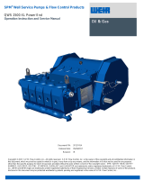
PUMP SERVICE
Corrosion
Fretting: To reduce the corrosion due to fretting effect we recommend to grease
the motor shaft with dedicated products (samples: lubricants based on MoS2,
Loctite® 8008, Molykote® G-n plus, Turmopast® MA2).
Fretting: To reduce the corrosion due to fretting effect, we recommend to
check the electric motor ground connection and to check that the shaft residual
currents are within the norms.
Leakage Prevention: In case of wear of shaft seal to avoid leakage, all pump
flanges with hallow shaft have a threaded ¼” gas thread that can be used for
drainage connection to the tank
Piping/Valves
▪Piping connected to pump MUST be independently supported and not
allowed to impose strains on pump casing including allowing for expansion
and contraction due to pressure and temperature changes.
▪To prevent foaming and air entrainment, all return lines in re-circulating
systems should end well below liquid surface in reservoir. Bypass liquid
from relief pressure and flow control valves should be returned to source
(tank, reservoir, etc.), NOT to pump inlet line.
▪Shut-off valves should be installed in both the suction and discharge lines
so pump can be hydraulically isolated for service or removal. All new piping
should be flushed clean before connecting to pump
▪Pipe strain will distort a pump. This could lead to pump and piping
malfunction or failure.
▪Return lines piped back to pump can cause excessive temperature
rise at pump which could result in catastrophic pump failure.
▪Use relief valves to protect pumps from overpressure. They need to be
connected to pump discharge lines as close to pumps as possible and
with no other valves between pumps and relief valves. Relief valve settings
should be set as low as practical.

thermaltransfer.com ttp-sales@apiheattransfer.com +1.262.554.8330
▪DO NOT set relief valve higher than maximum pressure rating of pump,
including pressure accumulation at 100% bypass. Relief valve return lines
should NOT be piped into pump inlet lines because they can produce a
loop that will overheat pump. This pump is a positive displacement type.
It will deliver (or attempt to deliver) flow regardless of back-pressure on
unit. Failure to provide pump overpressure protection can cause pump or
driver malfunction and/or rupture of pump and/or piping.
Suction Line/ Suction Strainer/Filter
▪The suction line should be designed so pump inlet pressure, measured at
pump inlet flange, is greater than or equal to the minimum required pump
inlet pressure (also referred to as Net Positive Inlet Pressure Required or
(NPIPR). Velocity in suction line should be kept within 1.6-4 ft/s (0,5-
1,2 m/s). Suction line length should be as short as possible and equal
to or larger than pump's inlet size. All joints in suction line must be tight
and sealed. If pump cannot be located below liquid level in reservoir, it
necessary either to position the suction or install a foot valve so liquid
cannot drain from pump while it is shut down. When pump is mounted
vertically with drive shaft upward, or mounted horizontally with inlet port
opening other than facing upward, a foot valve or liquid trap should be
installed in suction line to prevent draining. The suction line should be filled
before pump start-up.
▪DO NOT operate the pump without liquid or under severe cavitation
▪Pump life is related to liquid cleanliness. Suction strainers or filters
should be installed in all systems to prevent entry of large contaminants
into pump.
▪The purpose of a suction strainer or filter is for basic protection of internal
pumping elements. It should be installed immediately ahead of inlet port.
This location should provide for easy cleaning or replacement of strainer
element. Appropriate gages or instrumentation should be provided to
monitor pump pressure. Pressure drop across a dirty strainer must not
allow inlet pressure to fall below NPIPR. The pressure drop across the
strainer should preferably not exceed 1.45 PSIG (0,1 BAR) at maximum
flow rate and normal operating viscosity. General guidelines for strainer
sizing are as follows:
▪When pumping relatively clean viscous liquids (over 1000 cSt), use 10 to
12 mesh screens or those with about 1/16 inch (1,5mm) openings.
▪When pumping relatively clean light liquids such as distillate fuels, hydraulic
oil and light lube oils, use suction strainers of 100 to 200 mesh.
▪When pumping heavy crude oils, use 5 to 6 mesh strainer screens or those
with or about 1/8 inch (3mm) openings.
▪When pumping relatively clean distillate fuels in high pressure fuel supply
systems, use 25 micron “absolute” filters for three screw pumps and
10 micron “absolute” filters for gear pumps.
▪Make sure size/capacity of strainer or filter is adequate to prevent having
to clean or replace elements too frequently.
Gauges
Pressure and temperature gauges are recommended for monitoring the pump’s
operating conditions. These gauges should be easily readable and placed as
close as possible to pump’s inlet and outlet flanges
Pumped Liquids
NEVER operate a pump with straight water (water/glycol is okay). The pump
is designed for liquids having general characteristics of oil. In closed or
re-circulating systems, check liquid level in tank before and after start-up to
be sure it is within operating limits. If initial liquid level is low, or if it drops as
system fills during start-up or pumping operations, add sufficient clean liquid to
tank to bring liquid to its normal operating level. Only use liquid recommended
or approved for use with the equipment. Regular checks should be made on the
condition of the liquid. In closed systems, follow supplier’s recommendations
for maintaining liquid and establishing when liquid is to be changed. Be sure
temperature is controlled so liquid cannot fall below its minimum allowable
viscosity which occurs at its maximum operating temperature. Also, ensure that
maximum viscosity at cold start-up does not cause pump inlet pressure to fall
below its minimum required value.
NEVER operate a pump without liquid in it!
Operate only on liquids approved for use with pump.
COLW Series continued
/