
thermaltransfer.com ttp-sales@apiheattransfer.com +1.262.554.8330
AOC Series
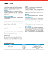
Symptom Possible Cause Corrective Action
Not cooling adequately
Not enough air flow Consult specifications and adjust if required
Unit is fouled Clean exchanger (see maintenance)
Unit is undersized Check specifications and change size if necessary
Leaking at connections Not tight Tighten carefully
No thread sealant Remove pipe, apply thread sealant and reinstall
Read carefully before attempting to assemble, install, operate or maintain
the product described. Protect yourself and others by observing all safety
information. Failure to comply with instructions could result in personal injury
and/or property damage! Retain instructions for future reference.
Description
AOC series forced air oil coolers are used for high-efficiency oil cooling in
hydraulic systems. Units utilize the latest in heat transfer technology to reduce
the physical size and provide the ultimate in cooling capacity. By maintaining
a lower oil temperature, hydraulic components and fluids work better and
have a longer life expectancy.
General Safety Information
1. Do not exceed the pressure rating of the oil cooler, nor any other
component in the hydraulic system.
2. Do not exceed the published maximum flow rates as the potential
can result in damage to the hydraulic system.
3. Release all oil pressure from the system before installing or servicing the
oil cooler.
4. These oil coolers are not suitable for use in hydraulic systems operating
with water-glycol or high water base fluids without a corrosion inhibitor
suitable for aluminum and copper component protection.
Unpacking
After unpacking the unit. inspect for any loose, missing or damaged parts.
Any minor damage to the cooling fins can generally be corrected by gently
straightening them.
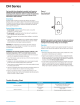
WARNING
Do not exceed the maximum pressure of 300 PSI, or the maximum
temperature of 350°F as oil cooler failure can occur.
1. These hydraulic oil coolers should be installed on either the low pressure
return line, or a dedicated recirculation cooling loop.
2. Turn off the hydraulic system and drain any oil from the return lines before
installing these coolers.
3. A strainer located ahead of the cooler inlet should be installed to trap scale,
dirt, or sludge that may be present in piping and equipment, or that may
accumulate with use. A thermostatic or spring loaded bypass/relief valve
installed ahead of the cooler may be helpful to speed warm-up and relieve
the system of excessive pressures.
Trouble Shooting Chart
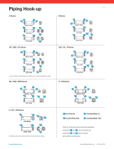
CAUTION Use of a back-up wrench is recommended to prevent twisting
of the manifolds when installing the oil piping. If pipe sealant is used on
threads, the degree of resistance between mating parts is less, and there
is an increased chance for cracking the heat exchanger fittings. Do not
over tighten.
4. Piping must be properly supported to prevent excess strain on the heat
exchanger ports.
Operation
Once unit is installed, turn the fan by hand to eliminate possible part
interference because of damage in shipment or installation. Observe the fan
operation upon initial startup. The system may then be operated.
Maintenance
Inspect the unit regularly for loose bolts and connections, rust and corrosion,
and dirty or clogged heat transfer surfaces (cooling coil).
Heat Transfer Surfaces
Dirt and dust should be removed by brushing the fins and tubes and blowing
loose dirt off with compressed air. Should the surface be greasy, the cooler
should be brushed or sprayed with a mild alkaline solution, or a non-
flammable degreasing fluid. Follow with a hot water rinse and dry thoroughly.
A steam cleaner may also be used effectively. Do not use caustic cleaners.
Casing Fan and Motor
Dirt and grease should be removed. Rusty or corroded surfaces should be
sanded clean and repainted.
Internal Cleaning
At least once a year, piping should be disconnected and degreasing agent
or flushing oil circulated through the unit to remove sludge from turbulators
and internal tube surfaces to return the unit to full thermal capacity. A
thorough cleaning of the entire system in the same manner is preferable
to avoid carry-over from uncleaned piping, pumps and accessories. The
strainer or any filtering devices should be removed and serviced following
this cleaning operation.
0916
-
 1
1

Ask a question and I''ll find the answer in the document
Finding information in a document is now easier with AI
Related papers
-
 Thermal Transfer RM Series Datasheet
-
 Thermal Transfer DH Series Datasheet
-
 Thermal Transfer DF Series Datasheet
-
 Thermal Transfer UC/UCV Series Datasheet
-
 Thermal Transfer EKT Series Datasheet
-
 Thermal Transfer AOVH Series Datasheet
-
 Thermal Transfer Fluid Water K Datasheet
-
 Thermal Transfer EK Series Datasheet
-
 Thermal Transfer COL series Datasheet
-
 Thermal Transfer ACOC/ACOCH Series Datasheet


Other documents
-
 Detroit Diesel MBE4000 Application And Installation Manual
-
Quincy Compressor QSI 1500 User manual
-
 WÄRTSILÄ WÄRTSILÄ 50DF User manual
-
Perkins 4016 TAG1 Installation guide
-
Lincoln Electric Under Cooler Cart Operating instructions
-
Lincoln Electric IM723-A User manual
-
Bosch Rexroth RE15325-WA User manual
-
Lincoln Electric Cool Arc 40 Operating instructions
-
-

