Page is loading ...

1
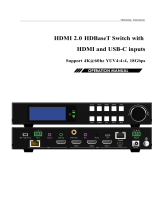
70m 4x4 HDMI 2.0 HDBaseT Matrix
with 4 hdmi loop out
Support 4K@60hz YUV4:4:4, 18Gbps, HDR

2
Operating Instruction
Thank you for purchasing this product. For optimum performance and safety,
please read these instructions carefully before connecting, operating or adjusting
this product. Please keep this manual for future reference.
SURGE PROTECTION DEVICE RECOMMENDED
This product contains sensitive electrical components that may be damaged by
electrical spikes, surges, electric shock, lightning strikes, etc. Use of surge
protection systems is highly recommended in order to protect and extend the life
of your equipment.

3
Operating Instruction
Catalogue
1. Features............................................................................................................................................. 4
2. Package Contents.............................................................................................................................. 4
3. Specifications.................................................................................................................................... 4
4. Panel Descriptions.............................................................................................................................5
5. Wiring Diagram.................................................................................................................................6
6. Input / output channel key operation................................................................................................ 7
7. Video switching operation................................................................................................................ 8
7.1. Video switch...........................................................................................................................8
7.2. Video Control......................................................................................................................... 8
The specific operation as follows:........................................................................................ 8
7.3. Audio Control.......................................................................................................................10
7.4. EDID Set Mode Interface.................................................................................................... 11
7.5. Preset Interface.....................................................................................................................12
7.6. SETUP mode Interface........................................................................................................ 13
7.6.1. RS-232 Baud Rate setting.........................................................................................14
7.6.2. DHCP On/Off setting................................................................................................14
7.6.3. POC power switch.................................................................................................... 14
7.6.4. Reboot setting........................................................................................................... 15
7.6.5. Factory setting...........................................................................................................15
7.7. INFO mode Interface........................................................................................................... 16
8. Audio Extraction............................................................................................................................. 17
9. Remote Control Description........................................................................................................... 18
10. IR system.......................................................................................................................................18
11. Command Control.........................................................................................................................19
12. Web Control.................................................................................................................................. 20
12.1. Enter Web and Control.......................................................................................................21
12.2. “Status” interface:...................................................................................................... 21
12.3. “Input” interface:....................................................................................................... 22
12.4. “Output” interface:.....................................................................................................22
12.5. “Preset” interface:...................................................................................................... 23
12.6. “User EDID” interface:..............................................................................................23
12.7. “Network” interface:..................................................................................................23
12.8. “System” interface:.................................................................................................... 23
13. FW UPGRADE.............................................................................................................................24
13.1. MCU Upgrade:...........................................................................................................24
13.2. CPLD Upgrade:......................................................................................................... 24
13.3. HTML (WEB GUI) Upgrade:....................................................................................25
MAINTENANCE............................................................................................................................... 26
PRODUCT SERVICE.........................................................................................................................26
WARRANTY...................................................................................................................................... 26

4
Operating Instruction
1. Features
Incorporate HDBaseT technology
4 x HDMI input and 4 x HDBaseT output with 4 x HDMI Loop out
HDMI 2.0 version support 4K@60Hz YUV4:4:4, 8bit, 18G, HDR10
Transmit up to 70m under 1080p, 40m under 4K@60Hz
HDCP 2.2/1.4 compliant
With wide-band Bi-Direction IR routed control(38~56KHz)
Support 4x Analog Audio input
Support 4x Analog Audio and 4x SPDIF Audio extraction output
Support Panel Button with LCD, IR Routing, RS232, TCP/IP, PC Tool Control
Support POC (Receiver powered by HDBaseT Matrix)
Support Micro USB for FW updating
2. Package Contents
1). 1x Main Unit (HDBaseT Matrix)
2). 1x DC24V4A Power adapter
3). 1x Remote control
4). 5xIR Transmitter cables, 5x Wide-Band IR Receiver cables
5). 1x CD for control software & user manual & Command list
6). 4x 3Pin plug for Analog audio output
7). 1U rack design metal case with 2 mounting ear
3. Specifications
Operating Temperature Range
-5 to +40°C(23 to +104 °F)
Storage Temperature Range
-10 to +60°C(-14 to +140 °F)
Operating Humidity Range
5 to 90 % RH (no condensation)
Input Video Signal
0.5-1.0 volts p-p
Input DDC Signal
5 volts p-p (TTL)
Bandwidth
18Gbit/s
Video Format Supported
4K@60Hz,YUV4:4:4 8bit
4k@30Hz/1080P/1080i/720P/576P/480P/576i/480i
HDCP Compliant
HDCP2.2 and HDCP1.4
Output Video
HDMI2.0 and HDMI 1.4 (over HDBaseT and HDMI)
Audio Format Supported
PCM, Dolby5.1, DTS5.1 digital audio
Maximum Transmission Distance
1080P 70m, 4K 40m
Power Consumption
68 watts (Max.)
Dimensions
L438 x W394 x H44 mm
Mass (Main Unit)
3 KG

5
Operating Instruction
4. Panel Descriptions
①LCD: Showing Matrix information
②Output button OUT1~8 & Input button IN1~8
③Function button: MUTE; MENU; UP; DOWN; LOCK; ENTER
①IR input port x4 & All in & IR output port x4 & All out
②Audio out (Analog x4; SPDIF x4)
③RS232 port
④FW update port
⑤HDMI Input x4 AUDIO IN (Analog x4)
⑥HDBaseT out x4 & HDMI Loop out x4
⑦Ethernet port
⑧Power On/Off
⑨Grounding

6
Operating Instruction
5. Wiring Diagram

7
Operating Instruction
6. Input / output channel key operation
Channel
Button method
Input 1-4
1. Directly press the number key, such as input channel 1, and select "1" to press (only
when the output port is selected, the input channel number will be valid)
2. Long press means all outputs select current input
Output 1-4
Directly press the number key, such as the output channel 2, press button "2" and press it
again to cancel the selection;
Long press output 4 to select all channels, and long press again to cancel
MENU
Function Button; Enter the function option or back to previous option
ENTER
Confirm Button: enter function selection mode
UP
Button for UP option
DOWN
Button for NEXT option
PRESET
Preset, short press to quickly enter the preset call function
LOCK
Long press to LOCK, Long press again to UNLOCK

8
Operating Instruction
7. Video switching operation
7.1. Video switch
The signal switch includes 4 free switching channels, which can be configured as input/output
according to the requirements, forming a matrix of 1 x 4 ~ 4 x 1, which can switch any input.
Signal to 1 channel output or all channel output.
The specific operation as follows:
Switch the input to the output
Operation format: "output channel" + "input channel"
For Example: Output port 2 switch to input 1
Operation: Press OUT number "2" + IN number "1" to complete the switch
7.2. Video Control
The video interface have two sub menu
1. Video Routing
2. Video On/Off
The specific operation as follows:
1.Video Switch
Switch any output to one input or all outputs to the same input, default PTP.
①Select“Video”in the menu and press“ENTER”

9
Operating Instruction
②Then use “UP””DOWN”button to select“Switching”
③Press“ENTER”enter next page
④Press “UP””DOWN”button to select the output(The fifth port means ALL)
⑤Press“ENTER”
⑥Press “UP””DOWN”to select the input
⑦Press“ENTER”,Switch Done
2.Video On/Off
Turn on/off any output video or all outputs video
①Select“Video”in the menu and press“ENTER”
②Then use “UP””DOWN”button to select“On/Off”
③Press“ENTER”enter next page
④Press “UP””DOWN”button to select the output(The 9th port means ALL)
⑤Press“ENTER”to select the HDMI 1~4; HDBT 1~4
⑥Press “UP””DOWN”to select “On”or “Off”
⑦Press“ENTER”,Switch Done

10
Operating Instruction
7.3. Audio Control
The Audio Control have three sub menu
1. Line Out
2. Audio Embed
3. Audio De-Embed
The specific operation is as follows:
1. Line Out
HDMI output audio switch. You can select a channel of HDMI output to mute the sound of the TV
2. Audio Embed
Audio can be embedded to HDMI input. The embedded sound will cover the original sound of the
signal source. You can select any input to embed
3. Audio De-Embed
You can set the output audio (analog audio and coaxial audio) at the same time. You can choose a
certain audio output or mute

11
Operating Instruction
7.4. EDID Set Mode Interface
Default EDID
Default1
4K60 444-LPCM: 2.0 FXN1234
Default2
4K60 420-LPCM: 2.0 FXN1234
Default3
4K30 444-LPCM: 2.0 FXN1234
Default4
1080P60 444-LPCM: 2.0 FXN1234

12
Operating Instruction
EDID Mode can set each input’s EDID, Include: Default EDID; User EDID; Copy EDID;
Copy HDBT EDID.
7.5. Preset Interface
The PRESET interface can save the current video, audio, EDID, system Settings, etc., and supports
8 different scenes. Scenes can be modified and cleared through web pages, commands, and panels.
The default preset is consistent with factory Settings

13
Operating Instruction
7.6. SETUP mode Interface
SETUP mode can set the device’s RS-232 baud rate, POC Switch, DHCP, Reboot, Factory
Specific operations are as follows

14
Operating Instruction
7.6.1. RS-232 Baud Rate setting
It has 4 kinds of baud rates inside the device: 9600; 19200; 57600; 115200
Default Baud Rate is: 115200
①Select“Setup”in the menu and press“ENTER”
②Then use “UP””DOWN”button to select the “BAUD”and press “ENTER”
③Press “UP””DOWN”button to select the baud rate and press “ENTER”to confirm
7.6.2. DHCP On/Off setting
On means Dynamic; Off means Static
①Select“Setup”in the menu and press“ENTER”
②Then use “UP””DOWN”button to select the “DHCP”and press “ENTER”
③Press “UP””DOWN”button to select“On”or“Off”and press “ENTER”to confirm
7.6.3. POC power switch
The POC interface can select a certain HDBT output switch to control POC power supply, and the
default POC is "On"

15
Operating Instruction
7.6.4. Reboot setting
7.6.5. Factory setting
Factory Run: Reset Video, Audio, EDID, Setup setting, Preset, Device name.
Factory User: Reset Video, Audio, EDID, Setup setting.

16
Operating Instruction
7.7. INFO mode Interface
Check the device information: IP or System information

17
Operating Instruction
8. Audio Extraction
HDMI audio output supports uncompressed audio PCM, compressed audio Dolby and DTS, with a
maximum support of 7.1 sound channels and a maximum sampling rate of 192KHz.
Analog audio supports PCM 2.0 channel.
S/PDIF audio supports Dolby or DTS, 5.1 channel.

18
Operating Instruction
9. Remote Control Description
①Standby Mode
②Lock or Unlock the Panel Button
③Choose output from 1-4
④Choose all the outputs.
⑤X: Turn on/off output port which you select
⑥PTP button: Mirror all inputs and outputs
(Ex. Input 1 to output 1, input 2 to output 2, etc)
⑦Choose input from 1-4
⑧Menu (back to previous option) button
⑨UP and DOWN button
⑩Enter button
10. IR system
The matrix can pass the IR signal through the IR system to the HDMI source or pass the IR signal
from the HDMI source to the HDMI sink
Dual way IR using:
Step1: “IR IN” is for HDBaseT output, “IR OUT” is for input channel
Step2: “IR IN ALL” Controlled by all input IR; “IR OUT ALL” Controlled by all output IR.
Step3: HDBaseT receiver support connect with IR receiver to control the Matrix by remote
Step4: Matrix IR channel “IR IN ALL” support connect with IR-RX cable to control the Matrix by
remote

19
Operating Instruction
11. Command Control
Control software operation:
The serial control software is illustrated with SSCOM32 as an example.
Basic Settings:
Double-click the software in the installation package to run specifically (as shown in
figure 1 below) and install the RS232 software on the computer.
Enter the main interface of the software, as shown in the figure below.
In the parameter configuration area, select the serial port number that the serial line
connects to the PC
Baud rate: 115200 (default)
Data location: 8.
Stop bit: 1
Check bit: no
Then can input commands in the command input area to control the local or remote
receiver
Instructions:
1. All commands start from “#”, command head “%c”: “d” parameters, “l” lock,
“s” save.
2. The “_” in the commands cannot omit. Parameter: %d: 0 means ALL.
3. Command head & Parameter1 & Parameter2... need to add one “SPACE”.

20
Operating Instruction
The following table is only an example. Please refer to the list of instructions.
Instruction
description
instruction
parameter 1
parameter 2
Video switch
#video_d
Audio Mode Switch
#audio_%c
in%d
enc=%d
EDID
#EDID_%c
In%d
cfg=%d
Please refer to the " Command list" for details.
Example: ALL output switches to input 4.
Operation format: #video_d out0 matrix=4
12. Web Control
1). Connect the Ethernet port of matrix to the Ethernet port on PC by a crossover cable with RJ45
connectors.
2). Configure your PC as follows:
1Click Start >Control Panel >Network and Sharing Center.
2Click Change Adapter Settings.
3Highlight the network adapter you want to use to connect to the device and click
Change settings of this connection.
3). The local Area commotion properties window for Network selection appears as below:
4). Click the Highlight Internet Protocol Version 4 (TCP/IPv4).
5). Click Properties.
6). Select Use the following IP Address for static IP addressing and fill in the details.
For TCP/IPv4 you can use any IP address in the range 192.168.1.1 to 192.168.1.255 (excluding
192.168.1.168).
7). Click OK.
8). Click Close.
Default IP Address: 192.168.1.168
MASK: 255.255.255.0
Gateway:192.168.1.1
MAC:0008-DCCA-CF3F
/