1
Mixed Input Type-C VGA HDMI
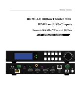
HDMI 2.0 HDBaseT Switch
Support 4K@60hz YUV4:4:4, 18Gbps,HDR

2
Operating Instruction
Thank you for purchasing this product. For optimum performance and safety,
please read these instructions carefully before connecting, operating or adjusting
this product. Please keep this manual for future reference.
SURGE PROTECTION DEVICE RECOMMENDED
This product contains sensitive electrical components that may be damaged by
electrical spikes, surges, electric shock, lightning strikes, etc. Use of surge
protection systems is highly recommended in order to protect and extend the life
of your equipment

3
Operating Instruction
Catalogue
1. Features................................................................................................................................................................4
2. Package Contents.................................................................................................................................................4
3. Specifications.......................................................................................................................................................4
4. Panel Descriptions................................................................................................................................................5
4.1 Menu Display.................................................................................................................................................6
5. Application Diagram............................................................................................................................................9
6. Remote Control Description................................................................................................................................9
7. IR system............................................................................................................................................................10
8. PC Tool Control.................................................................................................................................................10
8.1 Port setup......................................................................................................................................................10
8.2 Control interface...........................................................................................................................................11
8.3 Network Interface for device.......................................................................................................................12
9. Web Control.......................................................................................................................................................13
9.1 Change the IP address of your PC................................................................................................................13
9.2 Enter Web and Control.................................................................................................................................14
10. Command Control............................................................................................................................................15
11. Power Off and Reboot Input Priority Mode.....................................................................................................16
12. RS232 Pass through.........................................................................................................................................17
13. Micro USB for Firmware Upgrade..................................................................................................................17
13.1 MCU application layer upgrade.................................................................................................................17
13.2 GUI application layer upgrade...................................................................................................................17
13.3 GUI Web upgrade......................................................................................................................................17
MAINTENANCE..................................................................................................................................................19
PRODUCT SERVICE...........................................................................................................................................19
WARRANTY.........................................................................................................................................................19
MAIL-IN SERVICE..............................................................................................................................................19
LIMITEDWARRANTY LIMITS AND EXCLUSIONS.......................................................................................20

4
Operating Instruction
1. Features
Incorporate HDBaseT technology
HDMI 2.0 version support 4K@60Hz YUV4:4:4, 18G, HDR10
Support 1x VGA, 1x Type-C, 2x HDMI input
Support 1x HDMI and HDBT output simultaneously
Transmit up to 70m under 1080p@60Hz, 40m under 4K@60Hz
HDCP 2.2/1.4 compliant
Audio sampling rate upto 192KHz,support max 7.1CH
Support Analog audio embedded, Mic input
Support Analog/SPDIF audio extraction, analog output support PCM2.0,SPDIF output
support Dolby, DTS, max 5.1CH
With wide-band Bi-Direction IR routed control(38~56KHz), IR extend to control device
Support RS232 pass through
Support micro USB port for firmware upgrade
Support Panel Button with LCD, IR Routing, RS232, TCP/IP, PC Tool Control
Support POC (receiver powered by HDBaseT switch)
DC 24V/1A power supply
2. Package Contents
1). 1x Main Unit (HDBaseT Switch)
2). 1x Power supply DC24V/1A
3). 1x Remote control
4). 2xIR Transmitter cables, 3x Wide-Band IR Receiver cables
5). 1x CD for control software & user manual
6). 1x Receiver
3. Specifications
OperatingTemperatureRange -5to+40°C(23to+104°F)
Storage Temperature Range -10 to +60°C(14 to +140 °F)
OperatingHumidityRange 5to90%RH(nocondensation)
Input Video Signal 0.5-1.0 volts p-p
Input DDC Signal 5 volts p-p (TTL)
Bandwidth 18Gbit/s
Video Format Supported 4K@60Hz,YUV4:4:4
4k@30Hz/1080P/1080i/720P/576P/480P
HDCP Compliant HDCP2.2 and HDCP1.4
Output Video HDMI2.0 and HDMI 1.4 (over HDBaseT and HDMI)
Audio Format Supported PCM2.0, Dolby5.1, DTS5.1 digital audio
Maximum Transmission Distance 1080P 70m, 4K 40m(HDBT
output),4K/6M,1080p/15M(HDMI output)
Power Consumption 16.5wtts (Max.)
Dimensions 235 L x 137W x 39H mm
Mass (Main Unit) 1.175KG

5
Operating Instruction
4. Panel Descriptions Front Panel
①LCD: Showing HDBaseT switch informations ②Function button: Up, Down, Left, Right
③Function button: Menu, Enter
Rear Panel
1RS232: RS232 pass through/RS232 for PC tool control; Ethernet: IP/Web control;
FW: micro usb port for firmware update; IR Ext: IR extender for control HDBaset switch
2PC: AudioinforVGAinputonly; HDMI: Analog PCM2.0 audio embedded
③Audio SPDIF out(Dolby, DTS, Max 5.1CH)
④Analog PCM2.0 audio out
⑤IR-in/IR Out for remote controlling
⑥DC 24V/1A power supply
⑦MIC in:for 48V microphone/MIC device(MIC mode,support HDMI/Type C/VGA)
⑧MIC switch: Left switch for 48v microphone mode;
Middle switch for MIC mode; Right switch for line mode(Analog PCM2.0 audio embedded)
⑨Video input: TypeC-1: Type C in; PC-2: VGA in; HDMI in: HDMI-3/HDMI-4
⑩Video output: HDMI: HDMI out; HDBT/POC: HDBT out (connect HDBaset receiver/other HDBaset
products/Cascade)
Note:When you need to use MIC in/Analog audio embedded function,please set the audio input mode for
“Analog” by panel/PC tool/Web GUI first,then switch the MIC switch to choose the audio
format(48v/Mic/Line).
Left Guide button Short press:left/right choose function option in submenu,in MIC
input VOL/analog out VOL adjustment: left(-) right(+)
Right Guide button
Up Guide
b
utton Short press:up/down choose function option in submenu
Down Guide
b
utton
Ente
r
Confir
m
b
utton Short press:ente
r
submenu/back to last status
Menu Main Menu Short press:display/direct back to main Menu

6
Operating Instruction
4.1 Menu Display
Press Menu button,menu include VIDEO SET、AUDIO SET、EDID SET、MIC IN VOL SET、ANAL OUT
VOL SET、IP QUERY、UART QUERY、REST SET, press any button to highlight LED screen, and auto
turn dark without any operation after 20 seconds.
1). VIDEO SET: For input switch,select VIDEO SET and press enter button,press left/right button select current
input signal, press enter button again auto back to main menu to finish setting.
2). AUDIO SET: Audio input set,support 3 modes- HDMI(audio input for signal),Anal(audio embedded),
Mute(silent mode), select AUDIO SET,press enter button,then press left/right button select audio input,
press Enter again auto back to main menu to finish setting.

7
Operating Instruction
3). EDID SET: Support 4 modes- 4K60(Default),1080P(Default),COPY HDMI,COPY HDBT.
Select EDID SET, press Enter button,then press left/right button to select EDID for input, press Enter button
again auto back to main menu to finish setting.
4). MIC IN VOL SET: MIC input volume adjustment from 0~10,maximum 10 for loudest sound,minimum 0.
Select MIC IN VOL SET,press Enter button for volume control mode,press left button to decrease vol.,press
right button to increase vol.,press Enter button again auto back to main menu to finish setting.
5). ANAL OUT VOL SET: Analog audio out volume adjustment from 0~10,maximum 10 for loudest sound,
minimum 0. Select ANAL OUT VOL SET,press Enter button for volume control mode,press left button to
decrease vol.,press right button to increase vol.,press Enter button again auto back to main menu to finish setting.

8
Operating Instruction
6). IP QUERY: Default IP address 192.168.1.168,DHCP: off ,press left/right button select DHCP status,short
press Enter button and back to up one level.
7). UART QUERY: Device baudrate support 9600,19200,38400,57600,115200(default),not support to modify
by panel button,select UART QUERY,short press Enter button to check current baudrate.
8). SYSTEM RESET: Factory reset,short press Enter button direct and reset to factory defaults.

9
Operating Instruction
5. Application Diagram
6. Remote Control Description
①Standby Mode
②Mute
③Video input: “1” for TypeC-1;
“2” for PC-2(VGA);
“3” for HDMI-3;
“4”for HDMI-4;
④MIC in (ON/OFF)/VOL control;
⑤Analog audio out (ON/OFF)/VOL control;

10
Operating Instruction
7. IR system
The HDBaseT switch can pass the IR signal through the IR system to the HDMI source or pass the IR signal
from the HDMI source to the HDMI sink.
Dual way IR using:
Step1: “IR IN” is for HDBT output, “IR OUT” is for input channel.
Step2: HDBaseT receiver support connect with IR-RX cable to control the HDBaseT switch/DVD by remote.
Step3:HDBaseT switch support connect with IR-RX cable(IR in) to control TV by remote.
Step4: HDBaseT switch “IR Ext” support connect with IR-RX cable to control the HDBaseT switch by remote.
8. PC Tool Control
1).Download the “swe01b_4-Input HDMI Switcher.exe”software to your computer, then open it.
2).Using USB to RS232 cable connect to the RS232 portof HDBaseT switch.
3).Press “Search” button to find out the right port then click “Open Port”.
8.1 Port setup
1). Communication port setting: in PC windows system run the “swe01b_4-Input HDMI
Switcher.exe”software,in RS232 INFO. ,select correct port (communication port) and baud (should be same to
baudrate in UART QUERY for connection)
2). Click “Search”refresh communication port
3). “Open Port”: in disconnect status,”Close Port”: connected to device.

11
Operating Instruction
4 ).If popup“ERROR” means COM port is invalid and not be connected correctly,please press “OK”and refresh
again.
5). Below will show current COM port info. and baudrate when connected to device:
8.2 Control interface

12
Operating Instruction
1). Video Input: Switch Type C, VGA, HDMI input.
2). EDID Mode:
4K60: Default EDID 4K@60Hz
1080P: Default EDID 1080P@60Hz
HDMI: Copy HDMI out EDID for input(Copy mode)
HDBT: Copy HDBT out EDID for input(Copy mode)
3). Audio Input Mode: click to choose HDMI,Analog,Mute option (HDMI: audio of Type C/VGA/HDMI,
Analog: audio embedded/MIC in)
4). MIC: VOL control,the number “5”shows the current volume.(Pls note:you can only set the MIC VOL when
choose “Analog” for audio input)
5). Analog Output: VOL control,the number “5”shows the current volume.
(Pls note:you can not set VOL when audio input mode is “Mute”)
6) . Setting: Factory reset.
Note:Please set the audio input mode for “Analog” first by panel/PC tool/Web GUI when you need to use
MIC in/Analog audio embedded function.
8.3 Network Interface for device
①Mac Address: Can not modify
②IP Address: support modify
③Net Mask Address: support modify
④GateWayAddress:supportmodify

13
Operating Instruction
⑤DHCP ON/OFF
⑥Apply: Click to confirm modified static IP
Note:When you click for DHCP ON,then IP Address,Net Mask Address,Gate Way Address frames all become
grey and can not be modified.
9. WEB Control
9.1 Change the IP address of yourPC.
1). Connect the Ethernet port of HDBaseT switch to the Ethernet port on PC by a straight pin to pin
cable with RJ45 connectors.
2). Configure your PC as follows:
①Click Start >Control Panel >Network and Sharing Center.
②Click Change AdapterSettings.
③Highlight the network adapter you want to use to connect to the device andclick Change settings of this
connection.
3). The local Area commotion properties window for Network selection appears as below.
4). Click the Highlight Internet Protocol Version 4(TCP/IPv4).
5). Click Properties.
6). Select Use the following IPAddress for static IP addressing and fill in the details.
For TCP/IPv4 you can use any IP address in the range 192.168.1.1 to 192.168.1.255 (excluding 192.168.1.168).
7). Click OK.
8). Click Close.

14
Operating Instruction
(Default IP Address: 192.168.1.168; MASK: 255.255.255.0; Gateway:192.168.1.1)
9.2 Enter Web and Control.
1). Enter the default IP address of the matrix:192.168.1.168.
2).Youwill see following picture and control:
(No have interface to type in User Name and Password)
(The same interface to PC tool,please see the description in PC tool control)
Note: web control is recommended to use Google, fire fox, IE8 and above browsers, using other browsers
may not be compatible.

15
Operating Instruction
10. Command Control
Control software operation:
The serial control software is illustrated with SSCOM32 as an example. Basic Settings:
Double-click the software in the installation package to run specifically (as shown in figure 1 ) and
install the RS232 software on the computer.
Enter the main interface of the software, as shown in the figure below.
Please use USB to RS232 cable connect PC and device,open RS232 software.
In the parameter configuration area, select the serial number that the serial port connect with PC, and set
the baud rate of the communication protocol: 115200 (default), data bits: 8. Stop bits: 1, Parity: None,
you can input the instruction in the command input area and control the machine or remote receiver.

Operating Instruction
16
Instructions:
1). All commands start from “#”, “%d” parameters No.
2). The “_” in the commands cannot omit.
The following table is only an example. Please refer to the list of instructions.
Instruction
description Command format,
(%d:
p
aramete
r
numbe
r
)parameter 1 parameter 2
Comman
d
Quer
y
#cmd
Video Input Channel Switch #video_d in%d
1:TYPEC
2:VGA
3:HDMI1
4:HDMI2
Audio embedded in #audio_d enc=%d value=%d 0:HDMI
1:IIS,MIC
2:Mute
MIC VOL adjust numerical
range(0~10)
Audio IIS out VOL Set #audio_d iis=%d VOL adjust numerical
range(0~10)
EDID Mode Set #edid_d mode=%d 0:(4K60),1:(1080p)
2:(HDMI),3:(HDBT)
Factor
y
Reset #factor
y
Baudrate Set #uart baud=%d
0:9600
1:19200
2:38400
3:57600
4:115200
IP Query #ip help?
DHCP Set #ip dhcp=%d 0:Close ,1:Open
Please refer to above “Command list” for details.
For example:
Operation format
Video Input Channel Switch: #video_d in1 (Switch to Type C input)
Audio embedded in: #audio_d enc=1 value=7 (MIC VOL adjust to 7)
Audio IIS out VOL Set: #audio_d iis=7 (Analog audio VOL adjust to 7)
EDID Mode Set: #edid_d mode=2 (Copy EDID of HDMI out for input)
Baudrate Set: #uart baud=0 (Current baudrate set is 9600)
DHCP Set: #ip dhcp=1 (DHCP open)
11. Power Off and Reboot Input Priority Mode
When HDBaseT switch reboot and it inspect the current input signal in “None” status,device will auto switch to
higher priority input signal(If there is no higher priority input than current one,it will switch lower priority input).
Priority table for input:
Signal for Input Priority Switch Condition
HDMI 1 The highest Reboot and inspect HDMI1,if none signal,device switch
to next lower
p
riority input
HDMI 2 Second Reboot and inspect HDMI 2,if none signal,device auto
switch to higher priority input,if not,it switch to next
lower
p
riority input of signal
Type C in Third Reboot and inspect Type C,if none signal,device auto
switch to higher priority input,if not,it switch to next
lower
p
riority input of signal(VGA)
VGA in Fourth(the lowest) Reboot and inspect VGA,if none signal,device auto
switch to higher priority input,if not,it will keep current
input of signal(VGA)

Operating Instruction
17
Note:
1).If current input have signal,device will not auto switch to other input when reboot,it will keep current input.
2).When all input no have signal,device save last switch port when reboot.
3).The priority mode only valid when device with signal input.
12. RS232 Pass through
By RS232 Command , the HDBaseT switch can send RS232 data to control the receivers ,also the
receiver can send RS232 data to control the HDBaseT switch.
Please refer to the command list which included in the manual.
13. Micro USB for Firmware Upgrade
13.1 MCU application layer upgrade
1). The user should use the CD in colorbox,read and install software on PC;
2). Connect unit to PC with USB cable from micro USB port,click software,REFRESH and
choose correct COM port that connect to product,and baudrate 115200(default).The baud rate setting is
consistent with the host baud rate.
3). Type in “A1” in PORT and choose update program file in PATH,then click UPDATA wait for update until it
prompt “Succeed” informations and upgrade completed:
13.2 GUI application layer upgrade
1). Connect unit to PC with USB cable from micro USB port,click software,REFRESH and
choose correct COM port that connect to product,and baudrate 115200(default).The baud rate setting is
consistent with the host baud rate.
2). Type in “A1 01” in PORT and choose update program file in PATH,then click UPDATA wait for update
until it prompt “Succeed” informations and upgrade completed:

Operating Instruction
18
13.3 GUI Web upgrade
1).Connect unit to PC with USB cable from micro USB port,click software,REFRESH and
choose correct COM port that connect to product,and baudrate 115200(default).The baud rate setting is
consistent with the host baud rate.
2).Type in “F0 01” in PORT and choose update program in PATH,then click UPDATA wait for update until it
prompt “Succeed” informations and upgrade completed:
Note:If the upgrade progress bar is stopped in the middle of the upgrade, then the host will need
to be rebooted, then the serial port will be upgraded.

Operating Instruction
19
MAINTENANCE
Clean this unit with a soft, dry cloth. Never use alcohol, paint thinner of benzine to clean this unit.
PRODUCT SERVICE
(1) Damage requiring service:
The unit should be serviced by qualified service personnel if:
(a) The DC power supply cord or AC adaptor has beendamaged;
(b) Objects or liquids have gotten into theunit;
(c) The unit has been exposed to rain;
(d) The unit does not operate normally or exhibits a marked change in performance; The unit has been dropped
or the cabinet damaged.
(2) Servicing Personnel: Do not attempt to service the unit beyond that described in these operating
instructions.Refer all other servicing to authorized servicingpersonnel.
(3) Replacement parts: When parts need replacing ensure the servicer uses parts specified by the manufacturer
or parts that have the same characteristics as the original parts. Unauthorized substitutes may result in fire,
electric shock, or other Hazards.
(4) Safety check:After repairs or service, ask the servicer to perform safety checks to confirm that the unit is in
proper working condition.
WARRANTY
If your product does not work properly because of a defect in materials or workmanship, our Company
(referred to as "the warrantor" ) will, for the length of the period indicated as below, (Parts(2)Year,
Labor(90) Days) which starts with the date of original purchase ("Limited Warranty period"), at its
option either(a) repair your product with new or refurbished parts, or (b) replace it with a new of a
refurbished product. The decision to repair or replace will be made by the warrantor.
During the "Labor" Limited Warranty period there will be no charge for labor.
During the "Parts" warranty period, there will be no charge for parts. You must mail-in your product
during the warranty period. This Limited Warranty is extended only to the original purchaser and only
covers product purchased as new. A purchase receipt or other proof of original purchase date is
required for Limited Warranty service.
MAIL-IN SERVICE
When shipping the unit carefully pack and send it prepaid, adequately insured and preferably in the original
carton. Include a letter detailing the complaint and provide a day time phone and/or email address where you
can be reached.

Operating Instruction
20
LIMITED WARRANTY LIMITS AND EXCLUSIONS
1). This Limited Warranty ONLY COVERS failures due to defects in materials or workmanship, and DOES
NOT COVER normal wear and tear or cosmeticdamage.
The Limited Warranty ALSO DOES NOT COVER damages which occurred in shipment,
or failures which are caused by products not supplied by warrantor, or failures which result from accidents,
misuse, abuse, neglect, mishandling, misapplication, alteration, faulty installation, set-up adjustments,
misadjustment of consumer controls, improper maintenance, power line surge, lightning damage, modification,
or service by anyone other than a Factory Service center or other Authorized Servicer, or damage that is
attributable to acts of God.
2). THERE ARE NO EXPRESS WARRANTIES EXCEPT AS LISTED UNDER "LIMITED WARRANTY
COVERAGE". THE WARRANTORIS NOT LIABLE FOR INCIDENTAL OR CONSEQUENTIAL
DAMAGES RESULTING FROM THE USE OF THIS PRODUCT, OR ARISING OUT OF ANY BREACH OF
THIS WARRNTY.(As examples, this excludes damages for lost time, cost of having someone remove or re-
install an installed unit if applicable, travel to and from the service, loss of or damage to media or images, data
or other recorded content. The items listed are not exclusive, but are for illustrationonly.)
3). PARTSAND SERVICE, WHICH ARE NOT COVERED BY THIS LIMITED WARRANTY, ARE
YOUR RESPONSIBILITY
/