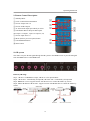
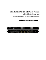
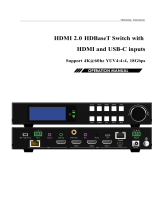
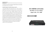
J-Tech Digital JTD564 4K 18G HDBaseT Matrix 4x4 with Audio De-Embedding and Web Control is a professional AV matrix that allows you to switch 4 HDMI sources to 4 HDBaseT outputs (with HDMI loop-out) and distribute them up to 70m/230ft (1080p) or 40m/131ft (4K) over a single Cat5e/6/7 cable. It supports 4K@60Hz YUV4:4:4 8bit, HDR10, HDCP 2.2/1.4, wide-band bi-directional IR control, audio de-embedding, and control via buttons, IR, RS232, TCP/IP, and a web interface. The matrix is ideal for applications such as home theaters, conference rooms, and digital signage.
J-Tech Digital JTD564 4K 18G HDBaseT Matrix 4x4 with Audio De-Embedding and Web Control is a professional AV matrix that allows you to switch 4 HDMI sources to 4 HDBaseT outputs (with HDMI loop-out) and distribute them up to 70m/230ft (1080p) or 40m/131ft (4K) over a single Cat5e/6/7 cable. It supports 4K@60Hz YUV4:4:4 8bit, HDR10, HDCP 2.2/1.4, wide-band bi-directional IR control, audio de-embedding, and control via buttons, IR, RS232, TCP/IP, and a web interface. The matrix is ideal for applications such as home theaters, conference rooms, and digital signage.


-
 1
1
-
 2
2
-
 3
3
-
 4
4
-
 5
5
-
 6
6
-
 7
7
-
 8
8
-
 9
9
-
 10
10
-
 11
11
-
 12
12
-
 13
13
-
 14
14
-
 15
15
-
 16
16
-
 17
17
-
 18
18
-
 19
19
-
 20
20
-
 21
21
-
 22
22
-
 23
23
-
 24
24
-
 25
25
-
 26
26
-
 27
27


J-Tech Digital JTD564 4K 18G HDBaseT Matrix 4x4 with Audio De-Embedding and Web Control is a professional AV matrix that allows you to switch 4 HDMI sources to 4 HDBaseT outputs (with HDMI loop-out) and distribute them up to 70m/230ft (1080p) or 40m/131ft (4K) over a single Cat5e/6/7 cable. It supports 4K@60Hz YUV4:4:4 8bit, HDR10, HDCP 2.2/1.4, wide-band bi-directional IR control, audio de-embedding, and control via buttons, IR, RS232, TCP/IP, and a web interface. The matrix is ideal for applications such as home theaters, conference rooms, and digital signage.
Ask a question and I''ll find the answer in the document
Finding information in a document is now easier with AI
Related papers
-
 LINK-MI JTD3000 User manual
-
J-Tech Digital JTD183 User manual
-
-
J-Tech Digital JTDJTD-229 User manual
-
J-Tech Digital J-TECH DIGITAL JTD4KSP0108 Premium Quality Ultra HD User manual
-
J-Tech Digital JTD2994 User manual
-
-
-
-
J-Tech Digital JTDJTD-3003 User manual

Other documents
-
DirekTronik SX-SWE01B Operating instructions
-
 LINK-MI LM-SWE02 Owner's manual
-
 Foxun SX-SW07 User manual
-
-
-
WAGNER HDMI2SPW User manual
-
PTN MUH44E KIT User manual
-
 Comm-Tec MTX88UH2 User manual
-
 LINK-MI LM-MX15 User manual
-


