Page is loading ...

1135 SERIES WIRELESS SIREN
Installation Guide
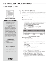
Figure 1: 1135 Wireless Siren
The 1135 Series Wireless Siren
provides up to 110decibels of
annunciation. The 1135 includes
a wall tamper and cover tamper,
Survey LED operation, and two
batteries. Multiple sirens can be
activated simultaneously by the
panel using the Trip with Panel
Bell option. This option allows the
siren to follow the panel bell output
including the bell cuto time.
The 1135E Wireless Siren also
features 128‑bit AES encryption.
Compatibility
• 1100X and 1100D Series
Wireless Receivers
• All DMP Burglary Panels
What is Included?
• One 1135 Series Wireless Siren
• Two 3.0V Lithium CR123A
Batteries
• Hardware Pack
1
PROGRAM THE PANEL
DESCRIPTION
To Follow Panel Bell (Option 1)
Refer to the panel programming guide as needed.
1. In OUTPUT INFO (XR150/XR550) or OUTPUT SETUP
(XT30/XT50, XTLplus, and XTLtouch), enter the output
number.
2. Enter the OUTPUT NAME and press CMD.
3. Enter the eight‑digit SERIAL# and press CMD.
4. Enter the SUPRVSN TIME and press CMD.
5. Leave TRIP WITH PANEL BELL as the default YES.
6. Set BELL CUTOFF to 1‑15 minutes.
Note: Outputs operate with a 3second response time when
used with the 1135‑W.
7. (1135E only) In SYSTEM OPTIONS, at 1100 ENCRYPTION,
select ALL to only add encrypted wireless devices to the
system. Select BOTH to allow both encrypted and non‑
encrypted wireless devices to be programmed.
8. (1135E only) The default passphrase appears at ENTER
PASSPHRASE. Press CMD to keep the default. Press any
select key or area to change the passphrase and enter an
8‑character hexadecimal string (0‑9, A‑F).
9. For wireless output troubles to display at a keypad on an
XR150/XR550 Series system, the keypad address must be
specified at the AUX 1 ZONES (Auxiliary 1 Zones) option in
the Status List programming menu. See the XR150/XR550
Programming Guide (LT‑1232) for more information.
To Stand Alone as an Output (Option 2)
To allow the1135 to be turned on or silenced by the panel, the
transmitter serial number must be programmed as an output in
OUTPUT INFORMATION. Refer to Silence the Sounder for more
information.
1. In OUTPUT INFO (XR150/XR550) or OUTPUT SETUP
(XT30/XT50, XTLplus, and XTLtouch), enter the output
number.
2. Enter the OUTPUT NAME.
3. Enter the eight‑digit SERIAL# and press CMD.
4. Enter the SUPRVSN TIME (Supervision Time) and press
CMD.
5. Set the TRIP WITH PANEL BELL option to NO.

2 1135 SERIES INSTALLATION GUIDE | DIGITAL MONITORING PRODUCTS
MOUNT THE 1135
4
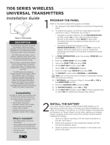
Figure 3: Wall Tamper
Wall Tamper
Mounting Hole
Wall Tamper Screw Hole
3
The 1135 provides a Survey LED capability to allow one person to confirm communication with the wireless
receiver or panel while the cover is removed.
1. With the cover removed, hold the siren in the exact desired location.
2. Press the case tamper switch to send data to the panel and determine if communication is confirmed
or faulty.
Confirmed: If communication is confirmed, for each press or release of the tamper switch, the LED
blinks immediately on and immediately off. Repeat this test to confirm five separate consecutive
LED blinks. Any indication otherwise means proper communication has not been established.
Faulty: If communication is faulty, the LED remains on for about 8 seconds or flashes
multiple times in quick succession. Relocate the siren or receiver until the LED confirms clear
communication.
SELECT A LOCATION
Commercial Installation
Standard Installation
1. Remove the cover from the 1135.
2. If using screws, place the supplied #6 screws into the mounting holes and secure the siren to the
surface. If using double‑sided tape, place the siren on the surface.
3. Place the cover back into place and secure the housing using the two locking screws.
Mount the siren away from metal objects. Do not install the siren within four feet of the panel as the RF gain
of the transmitter may inhibit proper communication.
1. With the cover already removed,
remove the PCB from the housing
to access the wall tamper screw
hole.
2. Mount the housing on a flat wall.
Use one of the provided screws
to anchor the housing through
the wall tamper screw hole. See
Figure3 for the wall tamper screw
hole location.
3. Place the supplied #6 screws into
the mounting holes and secure the
siren to the surface.
4. Snap the PCB back into the
housing attached to the wall.
5. Place the cover back into place
and secure the housing using the
two locking screws.
INSTALL THE BATTERIES
2
Before installing the batteries, program
the siren’s output number in the panel and
connect the receiver. Observe polarity
when installing the two CR123A batteries.
See Figure2.
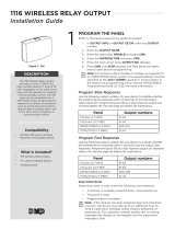
Figure 2: Mounting Holes and PCB Features
Red Survey LED
Case Tamper
Battery Location
Wall Tamper Header
100/110 dB Header
Sounder
Battery Location

1135 SERIES INSTALLATION GUIDE | DIGITAL MONITORING PRODUCTS 3
ADDITIONAL INFORMATION
Wall Tamper
A two‑position header is provided to disable the wall tamper. Refer to Figure 2. To disable the wall tamper, place the
jumper across the two pins of the header.
100/110 Decibel Jumper
The siren is equipped with a 100/110 decibel (dB) jumper and a two‑position header to change the decibel output. The
siren is shipped at the 110dB output level with the jumper placed on one pin for storage. If the 100dB setting is required,
place the jumper over both header pins. Refer to Figure2.
Battery Life Expectancy
Battery life expectancy for the siren is 3years when the siren is operated for 5minutes once a month.
DMP wireless equipment uses two‑way communication to extend battery life. To extend battery life further, operate the
siren infrequently and extend supervision time in panel programming. Multiple on/off siren operations and extreme hot
or cold environments will reduce battery life.
Replace the Battery
1. Remove the locking screws from the top and bottom of the siren housing.
2. Lift the cover from the bottom to remove it from the base.
3. Remove the old batteries and dispose of them properly. Always replace both batteries at the same time.
4. Install the two CR123 batteries and press into place. Refer to Figure 2 for battery locations.
5. Place the cover back onto the base and secure the housing using the locking screws.
Mount Outside
The temperature range for mounting outside is 32 ‑ 120 ° F with a humidity at 85% at 86 ° F. Do not mount the siren
where rain or water will damage the device.
Silence the Sounder
The following panel operations can silence the sounder:
• BELL OUTPUT (XR150/XR550only)—Program the output in BELL OUTPUT so the sounder turns o at the BELL
CUTOFF time if less than fifteen minutes
• Disarming—Program the output in ALARM ACTION for the zone that will be disarmed, then set the action to
STEADY
• OUTPUTS ON/OFF—From the User Menu, select OUTPUTS ON/OFF. Enter the output number and choose OFF
• Output followszone condition—Program the output in ALARM ACTION and set the action to FOLLOW. When
thetransmitterzone restores, the output is turned o

Designed, engineered, and
manufactured in Springfield, MO
using U.S. and global components.
LT-1106 1.06 20265
INTRUSION • FIRE • ACCESS • NETWORKS
2500 North Partnership Boulevard
Springfield, Missouri 65803-8877
417.831.9362 | DMP.com
Patents
U. S. Patent No. 7,239,236
Certifications
FCC Part 15 ID: CCKPC0123R8
Industry Canada: 5251A-PC0123R8
Underwriters Laboratory Listed:
ANSI/UL 1023 Household Burglar Alarm System Units
ANSI/UL 1610 Central Station Burglar Alarm Units
ANSI/UL 985 Household Fire Warning System
1135 SERIES
WIRELESS SIREN
Specifications
Battery
Life Expectancy 3 years
Type 3.0 V lithium CR123A
Internal Sounder Type Y
Tone Output 100dBA at 1meter
Frequency Range 905-924 MHz
Housing Material Flame retardant ABS
Dimensions 4.5 L x 4.5 W x 1.25 H in
11.4 L x 11.4 W x 3.2 H cm
Color White
FCC INFORMATION
This device complies with Part 15 of the FCC Rules. Operation is subject to the following two conditions:
1. This device may not cause harmful interference, and
2. this device must accept any interference received, including interference that may cause undesired operation.
The antenna used for this transmitter must be installed to provide a separation distance of at least 20 cm (7.874 in.) from
all persons. It must not be located or operated in conjunction with any other antenna or transmitter.
Changes or modifications made by the user and not expressly approved by the party responsible for compliance could
void the user’s authority to operate the equipment.
Note: This equipment has been tested and found to comply with the limits for a Class B digital device, pursuant to
part 15 of the FCC Rules. These limits are designed to provide reasonable protection against harmful interference in
a residential installation. This equipment generates, uses and can radiate radio frequency energy and, if not installed
and used in accordance with the instructions, may cause harmful interference to radio communications. However,
there is no guarantee that interference will not occur in a particular installation. If this equipment does cause
harmful interference to radio or television reception, which can be determined by turning the equipment o and on,
the user is encouraged to try to correct the interference by one or more of the following measures:
1. Reorient or relocate the receiving antenna.
2. Increase the separation between the equipment and receiver.
3. Connect the equipment into an outlet on a circuit dierent from that to which the receiver is connected.
4. Consult the dealer or an experienced radio/TV technician for help.
INDUSTRY CANADA INFORMATION
This device complies with Industry Canada Licence‑exempt RSS standards. Operation is subject to the following two
conditions:
1. This device may not cause interference, and
2. this device must accept any interference, including interference that may cause undesired operation of the device.
This system has been evaluated for RF Exposure per RSS‑102 and is in compliance with the limits specified by Health
Canada Safety Code 6. The system must be installed at a minimum separation distance from the antenna to a general
bystander of 7.87 inches (20 cm) to maintain compliance with the General Population limits.
Le présent appareil est conforme aux CNR d’Industrie Canada applicables aux appareils radio exempts de licence.
L’exploitation est autorisée aux deux conditions suivantes:
1. l’appareil ne doit pas produire de brouillage, et
2. l’utilisateur de l’appareil doit accepter tout brouillage radioélectrique subi, même si le brouillage est susceptible
d’en compromettre le fonctionnement.
L’exposition aux radiofréquences de ce système a été évaluée selon la norme RSS-102 et est jugée conforme aux limites
établies par le Code de sécurité 6 de Santé Canada. Le système doit être installé à une distance minimale de 7.87 pouces
(20 cm) séparant l’antenne d’une personne présente en conformité avec les limites permises d’exposition du grand
public.
/