Page is loading ...

Revised 04/04/08 ALLURE ELECTRONIC Install & Ops Apr08 Page 1 of 23
ALLURE
GAS OPEN FIRE
ELECTRONIC MODELS:
930-730-630
APRIL 2008
INSTALLATION
OPERATION, MAINTENANCE &
WARRANTY INFORMATION
These instructions should be stored in a convenient safe place for ready reference.

Revised 04/04/08 ALLURE ELECTRONIC Install & Ops Apr08 Page 2 of 23
Designed and built by:
YUNCA GAS
2 Donald Street, Kaikorai Valley
PO Box 500, Dunedin 9054.
Phone 03 488 4342 Fax 03 488 1017
CONTENTS PAGE
INTRODUCTION 2
CAUTIONS and MAINTENANCE 3
INSTALLATION and SERVICE
DIMENSIONS and CLEARANCES 4
FRAMING and CLADDING 5
FLUE INSTALLATION 6 – 7
PLACING of Unit 8
CONNECTION TO GAS SUPPLY & TESTING PRESSURES 9 – 11
REMOVING PANELS and PARTS for SERVICE 12 - 13
COAL AND LOG LAYOUT 14 - 15
OPERATION and COMMISSIONING 16
MAINTENANCE 17
Appendix A
FAULT FINDING GUIDE & WIRING DIAGRAM 17 - 19
Appendix B
SPARE PARTS LIST 20 - 21
Appendix C
WARRANTY 22
Appendix D
WARRANTY REGISTRATION 23
INTRODUCTION
Welcome and congratulations on purchasing your YUNCA ALLURE INDOOR ELECTRONIC
CONTROL flued gas open fire. Please read these Operating Instructions carefully before
attempting to operate the heater, and ensure all members of your home understand how this
elegant heater functions. If you have any questions please contact your Yunca dealer.
These instructions cover only the INDOOR ELECTRONIC CONTROL models.
Please fill out the warranty on the last page, and return the registration form promptly.
The YUNCA ALLURE INDOOR ELECTRONIC CONTROL FLUED GAS FIRE is a gas-fired,
conventionally vented, room heater that has Infra-red remote (electronic) start up and operation.
It is manufactured to New Zealand standards.

Revised 04/04/08 ALLURE ELECTRONIC Install & Ops Apr08 Page 3 of 23
CAUTIONS:
The Yunca Allure Electronic requires 240v power to operate. ENSURE THAT THE POWER
SWITCH IS READILY ACCESSIBLE (DO NOT install the switch inside any cavity area).
This appliance must be flued to the atmosphere.
This installation and any future service or repair work must be carried out by a suitably qualified
person and comply with the current New Zealand (Australian installation code) NZS 5261:1996
(AG 601:2002)
Control valve compartments, burners, fan, and air circulating passageways of the ALLURE must
be kept free from any lint and dust build-up to ensure efficient and safe operation of the heater.
DO NOT PLACE ARTICLES ON OR AGAINST THIS APPLIANCE.
DO NOT USE OR STORE FLAMMABLE MATERIALS NEAR THIS APPLIANCE.
DO NOT SPRAY AEROSOLS IN THE VICINITY OF THIS APPLIANCE WHILE IT
IS OPERATIONAL.
ENSURE THAT HOME VENTILATION SYSTEMS DO NOT AFFECT THE DRAW
OR FLAME PATTERN OF THE FIRE.
STAINLESS STEEL FASCIAS…
are shipped with protective plastic in place to reduce the risk of damage in
transit. Remove this plastic immediately before fitting the fascia to the fire.
Do not use abrasive cloths or cleaners on stainless steel fascias. Use only
specialised Stainless Steel cleaners available from your local hardware
store.
MAINTENANCE
YUNCA GAS HIGHLY RECOMMENDS THAT a qualified service person should conduct an
annual inspection and undertake any maintenance required on your Yunca Allure.
Its venting and installation must be checked to keep it running safely and efficiently.
Procedures should be performed only by a qualified service person.
The gas supply and electrical power should be isolated whenever any maintenance
procedures are undertaken.

Revised 04/04/08 ALLURE ELECTRONIC Install & Ops Apr08 Page 4 of 23
DIMENSIONS and CLEARANCES
Diagrams on the following pages are not to scale. All measurements are in millimetres.
The Yunca Allure flued gas fire is to be installed with clearances equal to, or greater than,
those recommended on the following pages, and must comply with NZS 5261:2003/AG601
ZERO CLEARANCE FIREBOX MANTEL
MODEL
F G H J K L X
FLUE DIA
INNER / OUTER
630
400 360 295 590 640 730 580 150/200
730
400 360 235 590 670 900 740 150/200
930
400 360 235 590 670 1100 940 200/250
Also available is a Bottom Fascia Strip for each model. This strip (730 & 930 - 85 mm high, 630
– 55mm high) is fitted below a regular three-sided fascia for a “picture frame” look.
CLEARANCES:
Floor protector – 300mm in front of and 100mm from side of firebox opening. 6mm minimum
thickness, using heat resistant materials.
Built in heat cell (zero clearance) requires minimum 25mm from combustibles all around
Mantel – 300mm above fascia required when the mantel
projects no more than 75mm.
Side to wall – 300mm from firebox opening.
FREESTANDING CABINET DIMENSIONS:
MODEL
M N O FLUE
DIA
MATCHING
DECORATIVE
LINER DIA
630 901 830 460 150 195
730 1060 830 460 150 195
930 1100 830 460 200 245
Rear clearance behind the cabinet is a minimum of 100mm.

Revised 04/04/08 ALLURE ELECTRONIC Install & Ops Apr08 Page 5 of 23
INSTALLATION INTO TIMBER FRAMED CHIMNEY CHASES:
FRAMEOUT INTO ROOM (requires ZERO CLEARANCE FLUE KIT)
Note: Framing minimum width from side of zero clearance firebox to side wall is 130mm (on each
side), i.e. the minimum width of the chimney chase shall be Dimension “B” + Dimension “C” +
260mm. This is to ensure air circulation around the appliance and avoid heat damage to wall
coverings. Installation must comply with NZS5261:2003/AG601
Two main configurations are used in new installations into new homes. Both require slightly different
approaches with air venting, but both require the use of zero clearance flue kits.
1. For dedicated chimney chases NOT open to the roof-ceiling cavity.
The chase must be vented at the bottom near the base level of the fireplace with 2 individual vents,
preferably one each side of the fire, each with a minimum size of 100mm x 50mm opening. Identical
vents must be repeated near the top of the chase, preferably directly above the bottom vents.
2. For chimney chases that open into and share the roof-ceiling cavity.
The chase must be vented at the bottom near the base level of the fireplace with 2 individual vents,
preferably one each side of the fire, each with a minimum size of 100mm x 50mm opening.
Air vents must be of a bird & vermin proof design and able to prevent rain penetration into the chase.

Revised 04/04/08 ALLURE ELECTRONIC Install & Ops Apr08 Page 6 of 23
ZERO CLEARANCE GAS FLUE KIT (3.6m): INSTALLATION INSTRUCTIONS
Yunca Gas ALLURE OPEN FIRE 630, 730 (150mm dia flue) 930 (200mm flue)
This flue kit has been manufactured in accordance with NZS 5261:1996. To ensure safety this flue kit must
be installed as outlined in these instructions. Appliance and flue clearances from combustible walls must be
in accordance with heater manufacturers specifications and NZS 5261:1996.
1) Locate heater in its proposed position and mark the points for penetration that are directly above the
centre of the heater’s flue outlet. Check that the heater’s location allows the OUTER HEAT SHIELD to
clear all structural timbers.
2) Cut 250mm square holes (930 model cut 300mm square holes) where penetration is required to
accommodate OUTER HEAT SHIELD.
NB: A minimum 25mm clearance is required between OUTER HEAT SHIELD and
combustible SURFACES.
3) Fit timber nogs around holes where necessary.
4) Assemble OUTER HEAT SHIELD lengths together ensuring seams are in line and
secure with 3 rivets or self-tapping screws. Lower OUTER HEAT SHIELD through the
roof or chimney structure and fit to heater spigot. Check height the OUTER HEAT
SHIELD penetrates roof or chimney structure.
The flue is required to be at least 500mm above the nearest point on any part of the
roof. It is recommended that in some instances extending the flue above the ridgeline
will be necessary. Refer to NZS 5261:1996 for more information. Additional HEAT
SHIELDS may have to be added to ensure the correct roof penetration heights are
obtained.
5) Assemble the 150mm (930 model uses 200mm) stainless steel FLUE PIPES
together ensuring all seams are in line using 3 pop rivets or screws and seal joints with
appropriate sealant. (Use ST/ST rivets or screws)
6) Fit FLUE SPACER BRACKETS to FLUE if necessary to maintain air gap between
FLUE PIPES and OUTER HEAT SHIELD.
7) Lower stainless steel FLUE PIPES from the roof into the OUTER HEAT SHIELD
(crimped ends towards heater) and into the heater flue outlet. Lift OUTER HEAT
SHIELD for access and seal flue to heater stub.
8) Secure OUTER HEAT SHIELD to heater, if necessary.
9) Using ANGLE BRACKETS secure OUTER HEAT SHIELD to nogs around
penetration holes. NB A minimum 25mm clearance is required between OUTER
HEAT SHIELD and combustible surfaces
10) Fix an appropriate flashing around the OUTER HEAT SHIELD to seal onto the
roofing or chimney material.
11) Fix TOP FLUE SPACER BRACKET to the flue making sure lugs fit snugly inside OUTER HEAT SHIELD.
12) Fit GAS COWL into FLUE pushing down fully onto TOP SPACER BRACKET. Secure with a self-tapping
stainless steel screw.
YUNCA ZERO CLEARANCE FLUE KIT CONTENTS
630 & 730 models:
3 x 150mm x1200mm StSt Flue 1 x 200mm x 1200mm Galv liner (plain both ends)
1 x Std Gas cowl 2 x 200mm x 1200mm Galv liner (swaged one end)
1 x Bottom spider 2 x inner / outer flue spacers
930 model:
3 x 200mm x1200mm StSt Flue 1 x 250mm x 1200mm Galv liner (plain both ends)
1 x Std Gas cowl 2 x 250mm x 1200mm Galv liner (swaged one end)
1 x Bottom spider 2 x inner / outer flue spacers
N.B. It is the responsibility of the installer to ensure that the installation of this flue kit complies with
the appliance manufacturers specifications for flues and those relevant Local Body requirements are
adhered to. Also refer to page 7.
Flue pipe
to be no
more than
25mm
higher
than outer
liner
Outer:
plain both
ends
Outer:
swaged
one end

Revised 04/04/08 ALLURE ELECTRONIC Install & Ops Apr08 Page 7 of 23
N.B. Diagram is for INDOOR installations, NTS for illustration purposes
(930 model uses 200mm flue, 250mm liner)
CONDITIONS FOR FLUES.
1. The Flue Shall Extend to:
a) In the case of a Pitched roof, Not less than 600 mm above the Highest Point of the
Roof.
b) In the case of a Flat roof, (ie. With a Pitch of less than 30°) not less than 1500 mm
above the Highest Point of the Roof.
c) In any case the length of the Flue shall be not less than 3.6 metres from the Top of
the Appliance Flue Spigot.
2. Minimum Total Flue Length = 3.6 metres
3. Flue must be 1.2 metres high before any Lateral is fitted.
4. Any Lateral run in a Flue shall be:
a) No more than 1.0 metre in the horizontal plane
b) Not be less than 45 degrees above the horizontal plane.
TYPICAL FLUE INSTALLATION
(FREESTANDING)

Revised 04/04/08 ALLURE ELECTRONIC Install & Ops Apr08 Page 8 of 23
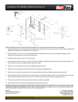
PLACING
The unit should be bolted to the floor to ensure no movement in the event of an earthquake or
similar.
(FIG 1)
Laying of the gas pipes and the electrical supply may need to be completed before the heater
is finally positioned. (Fig 2.) (6mm dia x 50mm Coach Bolts Supplied).
If the appliance is being attached to a concrete floor dyna bolts should be used, if the floor is
wooden the bolts used should be long enough to go fully through the floorboards and fixed with
nuts and washers from the underside.
(Fig 1.)
(Fig 2.)
30 mm
15 mm
15 mm
80 mm
Gas Pipe
Hole
Electrical
Cable
Bolt Points
Test Point
Grate
Cowl back

Revised 04/04/08 ALLURE ELECTRONIC Install & Ops Apr08 Page 9 of 23
CONNECTION TO GAS SUPPLY AND TESTING PRESSURES
ELECTRICAL:
The unit is connected to the mains supply (240 50Hz 0.5Amp) via the 3m flex with three-pin plug.
GAS SUPPLY:
Burn only the fuel for which the appliance is equipped. The data plate affixed to the base of the appliance
specifies the gas type, which the appliance is factory equipped for.
CONNECTION:
The gas inlet is a Titon 45° 3/8” Tube (LPG) or a Titon 45° 1/2” tube (NATURAL GAS)
(Nut Supplied for Connection)
A separate gas isolation valve should be installed immediately up stream of the connection
to the appliance.
Important: Gas Pipe sizing: The supply pipe size should be determined from NZS 5261 to ensure
correct gas supply to the appliance. Incorrect pipe sizing WILL affect the performance of this appliance.
WARNING: To stop pipe compounds entering the gas line, do not apply sealing compounds to the
first two threads at the tip of any gas connection. All joints should be tested for leaks before operating the
fire.
Gas pressure requirements:
Correct gas pressure and the use of a properly sized gas supply line are essential for the safe and efficient
performance of this appliance. The inlet and outlet pressures at the control must be tested on installation.
Note: Improper gas pressure will affect heater performance, flame Colour or cause pilot malfunction.
Natural Gas:
Input 930: 53 MJ,
730: 50 MJ,
630: 35 MJ
Minimum inlet pressure 1.25 kPa (5"w.g.)
Maximum inlet pressure 5.0 kPa (20"w.g.)
Max Manifold Operating pressure 0.6 kPa with Burners on HIGH
0.25 kPa with Burners on LOW
LPG:
Input 930 & 730: 48 MJ
630: 35 MJ
Minimum inlet pressure 2.75 kPa (11"w.g.)
Maximum inlet pressure 3.5 kPa (14"w.g.)
Max Manifold Operating pressure 1.5 kPa with Burners on HIGH
0.7 kPa with Burners on LOW
CAUTION: Do not use this appliance if any part has been water damaged or exposed to
moisture causing corrosion.
A Qualified service technician should inspect the appliance and replace any part of the
gas system that has been water damaged.

Revised 04/04/08 ALLURE ELECTRONIC Install & Ops Apr08 Page 10 of 23
GAS PRESSURE TESTING
Use pressure test point (Fig 1) on manifold.
A manometer is required to check the gas supply and operating pressures.
To attach manometer, remove hearth, rear tray and baffle.
This will expose the control valve so manometer tubes can be attached to the pressure taps as
shown below.
(Fig 4.)
Important: Ensure Pressure Tap is tightened and checked for leaks after testing.
Control Valve, Parts (Fig 4 and Fig 5)
1. Main Gas Inlet.
2. Inlet Pressure Tap Point. Tighten to torque 1.0Nm
3. High Pressure Adjust (10mm Brass Nut)
4. Low Pressure Adjust (Red Plastic X Screw)
5. Outlet Pressure Tap Point. Tighten to Torque 1.0Nm
6. Main Gas Outlet.
1
6
5
4
2
3

Revised 04/04/08 ALLURE ELECTRONIC Install & Ops Apr08 Page 11 of 23
GAS PRESSURE TESTING (cont)
(Fig 5)
NOTE: Modulator pressure adjustments are factory set. It is not expected that adjustment will be
required during installation.
Setting Pressures: (Fig 4 and 5)
MAXIMUM PRESSURE: The modulator is adjusted by screwing IN Brass Nut “ 5 “ to increase
the outlet pressure and screwing OUT to decrease it.
MIMIMUM PRESSURE: Keep Brass Nut “5” stationary, screw IN the Red Plastic Screw “4” to
increase the pressure and screw it OUT to decrease the pressure.
Pilot Outlet
4
5

Revised 04/04/08 ALLURE ELECTRONIC Install & Ops Apr08 Page 12 of 23
REMOVING PANELS
1) GRATE Lift up and out.
2) HEARTH Lift up and out.
3) FASCIA FRONT Remove four screws, two are just in from the
sides at the top, and two at the bottom left and
right. Lift the fascia up and out.
3a) BOTTOM FASCIA STRIP (Not shown) This part may be fitted along the
base of a regular three-sided fascia to give a
“picture frame” effect. When the fascia front is
removed you will see where the bottom strip is
fitted using two screws.
4) TOP LOUVRE #1 (Top) Slides out.
5) TOP LOUVRE #2 (Bottom) Remove 2 screws and slide off.
6) BOTTOM CONTROL AND GRILL Remove 2 screws and lift out.
7) COWL TOP FRONT Remove 2 screws and slide out. This will give
access to flue spigot (visible when fascia is
removed).
1
2
3
6
4
5
7
3
3
3

Revised 04/04/08 ALLURE ELECTRONIC Install & Ops Apr08 Page 13 of 23
REMOVING PARTS FOR SERVICE
(FIRST TURN OFF GAS AND POWER)
1) Coals, Logs - Remove with care.
2) Grate - Lift up and out.
3) Hearth - Lift up and out.
4) Front Tray - Remove screw from centre hole and lift out.
5) Rear Tray - Remove screws from right and left side, lift out.
6) Burners - Lift out.
7) Manifold Baffles - Lift out. (left and right baffles)
SETTING THE FIRE
1) Replace all panels and grate.
2) Check for gas ignition, also check that the remote control operates flame
and fan boost before setting the fire.
3) Follow layout (see following pages) for setting of the fire.
4) Re-check gas ignition, remote control operation, etc as in #2 above.
5
6
5
7
4
Electronic Box

Revised 04/04/08 ALLURE ELECTRONIC Install & Ops Apr08 Page 14 of 23
LAYOUT FOR COALS: - ALL MODELS
Layout shown is for the 930 model using 13 coals per row. The 730 model uses 10 coals per row,
the 630 uses 8 coals per row (layout as shown below, from left to right).
Bottom Rear Row:
Bottom Front Row:
Top Rear Row:
Top Front Row:
930 = 26 x No1 Coals
26 x No2 Coals
(4 rows of 13)
730 = 20 x No1 Coals
20 x No2 Coals
(4 rows of 10)
630 = 16 x No1 Coals
16 x No2 Coals
(4 rows of 8)
2
1 2 1
2
1 2
2
1
1
1 2
1
2
1 2
1
2
1
2
1 1
2
1
2 1 2
1
2 1
2
1
21
2
1
2
1 2
1
2
1
12
2
1
2
1
2
2
1
1

Revised 04/04/08 ALLURE ELECTRONIC Install & Ops Apr08 Page 15 of 23
LAYOUT FOR COALS & LOGS
Coals 930: 13 x No1 730: 10 x No1 630: 8 x No1
13 x No2 10 x No2 8 x No2
Layout shown is for the 930 model using 13 coals per row. The 730 model uses 10 coals per row,
the 630 uses 8 coals per row (layout as shown below, from left to right).
Rear Row
Front Row
Logs 630 730 930
1 x B 1 x B 2 x B
1 x C 2 x C 1 x C
1 x D 1 x D 2 x D
1 2
1
2 1 2 1 2 1
2
2
1
2
1 2
1
2 1
21
2
1
12
2
1
630
730
C
B
D
930

Revised 04/04/08 ALLURE ELECTRONIC Install & Ops Apr08 Page 16 of 23
Commissioning
When installed the installer should operate the YUNCA ALLURE to ensure that all features are
operating correctly.
Eg. On / Off operation, ramp up and down of fan speed and flame height. Refer below.
Turning on your YUNCA ELECTRONIC ALLURE
1. Turn the Gas and Power supply on.
2. Press the On / Off button once. LED will light up on the front of the base.
3. The burners will light at the same setting and fan speed as they were when previously turned
off.
4. Adjust the Flame height button as required to achieve the required heat output.
5. Adjust Fan speed button to achieve the optimum speed.
Turning off (immediate, no timer delay).
1. Press On / Off button once.
Turning off (using timer delay).
2. Press the “Off (delayed)” button once.
3. The Receiver will flash to indicate the timer delay activated.
4. The fire will shut down after 30 minutes.
5. To restart, follow the to start procedure.
Fig 8: Hand Control
Direct the infra-red beam from this hand control to the receiver mounted
at the Control front. The receiver will “light up” when receiving a signal
from the hand control.
The hand control operates on 4 AAA size alkaline batteries. Remove the
battery cover on the back of the hand control to insert batteries paying
attention to the polarity.
Note: multiple pushes of a button may cause a lock out in the
electronics. If this happens turn the power supply off and restart
the Gas fire.
Pressing the On / Off button once will initiate the lighting sequence. The
Receiver will light up. The lighting sequence will take approximately 30
seconds and a faint clicking may be heard as sparking takes place.
Pressing the On / Off button a second time will turn off the fire.
Flame height (heat output) is increased by pressing on the + sign of
flame button and reduced by pressing the – sign of the flame button.
Fan speed is increased by pressing on the + sign of fan button and
reduced by pressing on the – sign of the fan button.
Pressing Off (Delayed) will initiate a 30-minute timer delay off.
This can be cancelled by re-pressing the Off (Delayed) button.

Revised 04/04/08 ALLURE ELECTRONIC Install & Ops Apr08 Page 17 of 23
Maintenance
YUNCA GAS HIGHLY RECOMMENDS THAT a qualified service should conduct an annual
inspection and undertake any maintenance required on your Electronic Allure.
Its venting and installation must be checked to keep it running safely and efficiently.
Procedures should be performed only by a qualified service person.
The gas supply and electrical power should be isolated whenever any maintenance procedures
are undertaken.
Appendix A
Fault Finding:
SYMPTOM PROBLEM CORRECTIVE ACTION
Excessive flue
noise
Gap between flue and
liner too large
Reduce to size stated on installation drawing page
6 or 7 – Item 11
Will not light No light at the Infra-
Red receiver
Check remote light is operating when a button is
activated. Change remote batteries, Check mains
power is on
Ensure beam from the remote
Check the fuse in the back of the control Box.
Remove rear tray to access.
No spark at pilot
burner.
Check connection between electrode in pilot
assembly and lead from control
Poor or no spark Clean any build up (Carbon) on or around the
Spark electrode.
Tracking of spark along spark electrode lead.
Replace the spark electrode
Damaged spark electrode lead, Replace
No gas at pilot burner Check that isolating valves are turned on and gas
is available.
Clean the gas ways of soot or foreign particles.
Check pilot hood for blockage
Remove pilot jet and blow clean.
Check for any obstructions in the gas line that may
cause low pressure or restrict flow.
Purge gas lines.
Sparks, but the length
is incorrect.
Spark gap should be 3-4mm between the
electrode and the pilot flame hood outlet.
No Supply Gas.
LPG -- Refill tank
Natural -- Check with gas supplier

Revised 04/04/08 ALLURE ELECTRONIC Install & Ops Apr08 Page 18 of 23
Fault Finding continued:
SYMPTOM PROBLEM CORRECTIVE ACTION
Pilot will not stay lit
Weak or improperly
located pilot flame.
Adjust the height of Flame Rod. The flame should
engulf the top 6mm of the thermocouple. Check
for carbon at pilot causing a short.
Gas Popping noise Broken Ceramic Filter Replace ceramic filter
Filter not sitting in
correct position
Reposition.
Faulty control. Replace 845 Sigma Control Valve and/or
Replace Electronic Controller Assembly
Soot is being
deposited on coals
or logs
Coals impinging the
flames
Re-position coals back against the stops
Remove any protruding point on the log.
There is insufficient
secondary air in the
combustion chamber.
Check the back of the Fire for blockages around
the air intake slots.
Check that the clearances around the appliance
match those stated in this manual
.
Flueway blocked Remove blockage. Check cowl
LPG gas mix incorrect Contact supplier to clean out bottle
Flame Height very
large or very low.
Use remote and Ramp up or down.
Check gas inlet pressure and running pressure
Check and set gas pressure to manufacturers
specifications.
Main burners
extinguishing.
Flue down draughting. This is caused by a vacuum in the room.
Turn off fire. Turn off all air conditioners, expelair
fans, other heaters etc.
Check air vents are in place to equalise internal air
pressure. Re-light fire.
.
Pilot flame is not large
enough.
Check that pilot assembly is correctly mounted
and that the pilot burner flame hood directs the
pilot flame over burners and flame rod.
Severe down draught. Ensure a recommended flue cowl has been fitted
and is still in place.
Pilot burning, no
gas to burners
Burner injectors may
be blocked.
Clean out injector orifice.
Faulty control Electronic Control Valve or Controller requires
replacement.

Revised 04/04/08 ALLURE ELECTRONIC Install & Ops Apr08 Page 19 of 23

Revised 04/04/08 ALLURE ELECTRONIC Install & Ops Apr08 Page 20 of 23
Appendix B: PART NUMBER
Yunca ALLURE Spare Parts - Name
6598M Remote Hand Control
6598P 845 Sigma Control Valve
6598Q Electronic Flame Control Assembly
6598R Flame Rod
6598S Spark Electrode
6505 Delta Pilot Burner
6500L Pilot Jet LPG 0.23 dia
6500N Pilot Jet NAT 0.35 dia
6606GO6 Pilot Pipe (630)
6606GO7 Pilot Pipe (730)
6606GO9 Pilot Pipe (930)
6601GO Burner (630: 4 Injectors. 730, 930: 5 Injectors)
6599GOA Injector 0.8 LPG
6599GOB Injector 0.7 LPG
6599GOW Injector Washer
Injector 1.3 NAT
6599GOC Injector 1.2 NAT
Burner Pipe
6791GO9 930 Manifold Assembly- ( No Jets )
6791GO7 730 Manifold Assembly- ( No Jets )
6791GO6 630 Manifold Assembly- ( No Jets )
6624GO Fan Assembly
Main Gas Pipe
NAT Burner Plug Insert
6950A1 Coal No 1
6950A2 Coal No 2
6950B Log B
6950C Log C
6950D Log D
Duroboard
6955GO6 Rear Tray (630)
6956GO6 Front Tray (630)
6958GO6L Manifold Baffle (630)
6955GO7 Rear Tray (730)
6956GO7 Front Tray (730)
6958GO7L Manifold Baffle Left hand Side (730)
6958GO7R Manifold Baffle Right Hand Side (730)
6955GO9 Rear Tray (930)
6956GO9 Front Tray (930)
6958GO9L Manifold Baffle Left hand Side (930)
6958GO9R Manifold Baffle Right Hand Side (930)
6904GO9T 930 Grate - Traditional
6904GO7T 730 Grate - Traditional
6904GO6T 630 Grate - Traditional
6904GO9C 930Grate - Contemporary
6904GO7C 730 Grate - Contemporary
6904GO6C 630 Grate - Contemporary
/