Page is loading ...

TM
2841 E. Industrial Drive Springfield, MO 65802-6310 800-641-4282
Digital Monitoring Products, Inc.
Installation/Users Guide
LT-0336 (7/97)

Page 2
2841 E. Industrial Drive Springfield, MO 65802-6310 800-641-4282
ETHER-COM Installation/User’s Guide
TABLE OF CONTENTS
Introduction......................................................................................................................................................3
Terms ..............................................................................................................................................................3
Introduction......................................................................................................................................................4
ETHER-COM Components .............................................................................................................................4
Installation .......................................................................................................................................................5
Select a Location .............................................................................................................................................5
Connect the ETHER-COM to a Serial Device..................................................................................................5
Connect the ETHER-COM to the Ethernet ......................................................................................................5
Provide Power .................................................................................................................................................5
Provide Power continued .................................................................................................................................6
Is It Working?...................................................................................................................................................6
Introduction......................................................................................................................................................7
IP Address Configuration.................................................................................................................................7
Incoming TCP/IP Logins ..................................................................................................................................8
Controlling Incoming Logins ............................................................................................................................8
Serial Port Logins ............................................................................................................................................8
Remote Console Logins ..................................................................................................................................9
Starting an Outbound Connection ...................................................................................................................9
Telnet ...............................................................................................................................................................9
Logout .............................................................................................................................................................9
Introduction....................................................................................................................................................10
Command Set ...............................................................................................................................................10
System Passwords ........................................................................................................................................10
Privileged Password ......................................................................................................................................10
Login Password .............................................................................................................................................10
TCP/IP Parameters........................................................................................................................................11
Serial Port Configuration................................................................................................................................11
Technical Support ..........................................................................................................................................13
Introduction....................................................................................................................................................13
Problems and Error Messages ......................................................................................................................14
Entering Commands at the Boot Prompt .......................................................................................................15
DB25 Connector Pinout .................................................................................................................................15
Modem Wiring ...............................................................................................................................................16
DSR (Data Signal Ready) versus CD (Carrier Detect)...................................................................................16
DTR (Data Terminal Ready)...........................................................................................................................16
Specifications ................................................................................................................................................16
Power Specifications......................................................................................................................................16
Temperature Limitations ................................................................................................................................16
Altitude Limitations.........................................................................................................................................16
Relative Humidity Limitations.........................................................................................................................16
Configuration for use with a DMP 462N or SCS-1 Receiver ..........................................................................17
XR200/462N..................................................................................................................................................17
Important Note...............................................................................................................................................17
SCS-1 Receiver.............................................................................................................................................17
Configuration for use with Remote Access+™ on a PC .................................................................................18
HST Monitoring .............................................................................................................................................18
Important Note...............................................................................................................................................18
Configuration for use with Remote Access+™ on a PC continued.................................................................19
Ether-Com™ Programming ...........................................................................................................................19
Important Note...............................................................................................................................................19
Section Page

Page 3
2841 E. Industrial Drive Springfield, MO 65802-6310 800-641-4282
ETHER-COM Installation/User’s
Guide
Introduction
The ETHER-COM is a multiprotocol serial server that provides Ethernet connections for personal computers, terminals,
modems, and devices that would not otherwise be connected to a network.
The ETHER-COM can be used in conjunction with Unix, NetWare, Windows NT, OS/2, and VMS hosts. Instead of requiring
the user to enter commands for connection manipulation, the ETHER-COM acts as a directly-attached serial device on the
host.
The ETHER-COM can be used to start outbound Ethernet connections to hosts on IPX/SPX, TCP/IP, and LAT networks. It
can also provide interactive access to a device connected to its serial port. However, unlike traditional print servers, the
ETHER-COM does not provide printing protocols such as LPR, RTEL, and PCONSOLE, or queueing support.
This manual explains how to install, configure, and use the ETHER-COM.
◆The remainder of this chapter outlines ETHER-COM functionality.
◆Chapter 2 explains how to install the ETHER-COM hardware and boot the server.
◆Chapter 3 details different ways to log into the ETHER-COM and prepare the server for configuration.
◆Chapter 4 covers basic configuration.
◆Appendices provide technical support, troubleshooting, pinout, and specification information.
If you are an experienced user who is familiar with networking and serial servers, you may prefer to skip the installation
information. Be sure to read the configuration chapter.
Terms
In this manual, the following terms are used to describe parts of a network.
◆Host A computer attached to the network. The term “host” is
generally used to denote interactive computers, or
computers that people can log into.
◆Node Any intelligent device directly connected to the Ethernet
network such as a host, a printer, or a terminal server. All
devices have their own Ethernet addresses. Devices
connected to the ETHER-COM are not nodes.
◆Service A resource that can be accessed locally or via the network.
For example, a host is a service to which terminals can
connect. The ETHER-COM can offer attached modems as
services to the network.
◆Session A logical connection to a service. A typical session is a
terminal connected to a host through the server.
◆Local Mode The ETHER-COM user interface. It is used to issue
configuration and session management commands and to
establish connections.
When in Local mode, users will see a “Local>” prompt.
INTRODUCTION

Page 4
2841 E. Industrial Drive Springfield, MO 65802-6310 800-641-4282
ETHER-COM Installation/User’s Guide
Introduction
This chapter covers the installation of the ETHER-COM in an Ethernet network and the attachment of an XR200/462N.
Basic knowledge of networking installation is assumed. Read this section completely before continuing.
ETHER-COM Components
The ETHER-COM front panel has a male DB25 serial connector. The rear panel has an RJ45 Ethernet connector, a reset
button, and a power connector. Use of the network and power connectors is discussed in the following section.
Figure 2-1: ETHER-COM™ Front Panel
Figure 2-2: ETHER-COM™ Rear Panel
Four LEDs are located on the top of the unit.
Figure 2-3: ETHER-COM Top Panel showing LEDs
The first LED is a power indicator, and should remain green while the ETHER-COM is plugged in. The second is a network
link indicator, and should remain green while the ETHER-COM is connected properly to the network. Throughout the
manual, these LEDs will be referred to as the Power and Link LEDs.
The remaining two LEDs indicate network and serial port activity. They will blink off, yellow, green, or red depending on the
current activity. In this manual, these LEDs are referred to as the OK and Serial LEDs.
Although a red LED during boot mode usually signals an error, red LED patterns are part of the normal opera-
tion of the ETHER-COM and are not necessarily indicative of errors or dangerous operation.
INSTALLATION
Serial
DB25 Serial Port
10BaseT 6V DC
RJ45 Ethernet Port Reset Button Power Connector
Reset
6V DC Reset
Serial
Ethernet
MSS1-T
Micro Serial Server
Power
Link
OK
Serial
TM

Page 5
2841 E. Industrial Drive Springfield, MO 65802-6310 800-641-4282
ETHER-COM Installation/User’s
Guide
Installation
Figure 2-4 shows an example hardware layout.
Figure 2-4: Example Hardware Layout
Select a Location
The ETHER-COM should be positioned close to the device it will be servicing but out of the way of everyday activity. Since
powering down the unit will terminate any active sessions, it may be desirable to place the server in a location secure from
user access. Also, be aware of the unit’s environmental operating limits and cabling limits. See Appendix D for details.
Connect the ETHER-COM to a Serial Device
The ETHER-COM is designed to connect to an RS232-based serial device. Connect one end of a serial cable to the DB25
connector on the front of the ETHER-COM. Connect the other end to the RJ jack on the 462N.
Initially, you may want to connect a terminal to the serial port. The terminal will display any error messages and will allow
you to view commands as you configure the ETHER-COM.
The serial port is initially set for 9600 baud, 8 data bits, one stop bit, and no parity.
Connect the ETHER-COM to the Ethernet
The ETHER-COM can be connected to a 10BASE-T Ethernet network. Connect the twisted-pair Ethernet cable to the RJ45
connector on the back of the ETHER-COM.
Provide Power
Attach one end of the power cable to the ETHER-COM; plug the other end into a wall outlet. At this point, there is power to
the server, so be sure to use appropriate care when handling the unit. There is no power switch on the ETHER-COM; power
will come on automatically when the unit is plugged in.
Check to see if the Power and Link LEDs on the front of the server light. If not, unplug the server and check the power supply,
then check the Ethernet connection and plug the server in again. If the LEDs still do not light, refer to Appendix B,
Troubleshooting.
INSTALLATION
10BaseT Hub
Twisted Pair
Netware
File Server Sun MicroVAX
MSS1-T
Serial
Device
XR200 Control
Panel/462N
ETHER-COM

Page 6
2841 E. Industrial Drive Springfield, MO 65802-6310 800-641-4282
ETHER-COM Installation/User’s Guide
Provide Power continued
Power-up Diagnostics
The ETHER-COM boot-up procedure consists of two steps. During normal operation, the boot process requires approximately
30 seconds to complete.
1. The ETHER-COM will run through a set of power-up diagnostics for approximately 5 seconds. The Power and Link
LEDs should remain solid green; the OK and Serial LEDs will show varying patterns corresponding to the test
being run.
The Power and Link LEDs should be solid green if the unit is plugged in and there is a valid connection to a network.
2. The ETHER-COM will determine if the code in the Flash ROMs is valid. If so, it will load that code and begin
normal execution. This requires approximately 5 seconds.
When the unit is running normally, the OK LED will blink green once every two seconds. If data is being transmitted on the
Ethernet port, the OK LED will blink yellow. The Serial LED will blink red when characters are transmitted through the
serial port, green when characters are received, and yellow when characters are both transmitted and received.
Is It Working?
If the ETHER-COM appears to be working (the Power and Link LEDs are lit, and the OK LED is blinking slowly) and the
unit is connected to the network, there are two ways to confirm that it is working correctly:
◆If you have a terminal attached, try logging in. If the ETHER-COM passes power-up diagnostics and you are
able to log in, the server is running normally.
◆If an IP address has been configured for the ETHER-COM (see page 7), ping the ETHER-COM from a
TCP/IP host.
unix% ping xxx.xxx.xxx.xxx
Figure 2-5: Pinging the ETHER-COM
When you are satisfied that the ETHER-COM is working properly, proceed to Getting Started (page 7). If the server does not
boot properly, see Appendix B, Troubleshooting.
INSTALLATION

Page 7
2841 E. Industrial Drive Springfield, MO 65802-6310 800-641-4282
ETHER-COM Installation/User’s
Guide
Introduction
This chapter covers all of the steps needed to get the ETHER-COM on-line and running. There are two basic methods used
to log into the ETHER-COM and begin configuration.
1. Serial Port Logins: Users can connect a terminal directly to the serial port, log in, and use the command line
interface to configure the unit.
2. Remote Console Logins: TCP/IP users can make a Telnet connection to the remote console port, port 7000.
It is important to consider the following points before logging into and configuring the ETHER-COM:
◆The ETHER-COM’s IP address must be configured before any TCP/IP functionality is available (see IP
Address Configuration).
◆Only one terminal may be connected to the serial port.
◆Only one person at a time may be logged into the remote console port, regardless of the protocol being used.
This eliminates the possibility of several people simultaneously attempting to configure the ETHER-COM.
◆Remote console logins cannot be disabled. The system manager should always be able to access the unit.
◆The remote console port is password protected. For more information on system passwords, see System
Passwords on page 10.
◆Connecting a terminal to the serial port or logging into the remote console port does not automatically create
privileged user status. You must enter the Privileged Password to configure the unit.
IP Address Configuration
For TCP/IP use, an IP address must be configured for the ETHER-COM before any TCP/IP functionality is available. The IP
address is configured using the serial console.
Using the Serial Console
When you connect a terminal and press the Return key, you will see either a Boot prompt or a Local prompt.
If the unit does not complete the Boot process, a Boot prompt will be displayed. When you see this prompt, you can enter
Boot Configuration Program (BCP) commands to get the unit up and running. For example, you can configure the unit’s IP
address.
Boot> CHANGE IPADDRESS 192.0.1.228
Figure 3-1: Entering the IP Address at the Boot Prompt
For more information on Boot Configuration Program (BCP) commands, refer to Entering Commands at the Boot Prompt
on page 15.
If the ETHER-COM is running normally when you press the Return key, a Local prompt will be displayed. You can become
the privileged user and enter the Change IPaddress command at this prompt.
Local>> CHANGE IPADDRESS 192.0.1.228
Figure 3-2: Entering the IP Address at the Local Prompt
GETTING STARTED

Page 8
2841 E. Industrial Drive Springfield, MO 65802-6310 800-641-4282
ETHER-COM Installation/User’s Guide
Incoming TCP/IP Logins
Telnet
To log into the ETHER-COM, type Telnet followed by the ETHER-COM’s IP address.
% telnet 192.0.1.88
Figure 3-3: Making a Telnet Connection
Unlike remote console logins (see page 9), incoming Telnet logins do not require the user to enter a login password.
Rlogin
Rlogin allows users to connect to a remote device as if they were on the local network. Rlogin is enabled by default, but can
be disabled with the Change Rlogin Disabled command.
Controlling Incoming Logins
Incoming Telnet logins are enabled by default, but can be disabled with the Change Incoming command. This command is
used with one of the following parameters:
◆Telnet Enables Telnet logins
◆None Disables Telnet and LAT logins
For security reasons, you may wish to disable incoming logins. If it is undesirable to disable incoming logins, the ETHER-
COM can be configured to require a login password for incoming connections with the Change Incoming Password command.
Local> CHANGE INCOMING PASSWORD
Figure 3-4: Configuring an Incoming Password
The incoming password feature can be disabled with the Change Incoming Nopass command.
Serial Port Logins
One way to connect to the ETHER-COM is to attach a terminal to the serial port and press the Return key. If the unit is not yet
configured, or if the booting attempt fails, a Boot prompt is displayed. This prompt enables you to enter a special set of
commands, called Boot Configuration Program (BCP) commands, which are discussed in Appendix B.
If the unit passes its power-up diagnostics and completes the boot procedure, the Local prompt should be displayed. Proceed
to the Configuration chapter to configure the unit using the command line interface.
GETTING STARTED

Page 9
2841 E. Industrial Drive Springfield, MO 65802-6310 800-641-4282
ETHER-COM Installation/User’s
Guide
Remote Console Logins
The ETHER-COM enables a TCP/IP user to configure the server through a single Telnet connection to the remote console
port, designated as port 7000. Connections to the console port cannot be disabled, for example, with the Change Incoming
command. This ensures that administrators will always be able to log into the port.
To connect to the remote console port, use the Telnet command followed by the ETHER-COM’s IP address and the remote
console port number.
% telnet 192.0.1.88 7000
Trying 192.0.1.88
Connected to 192.0.1.88
Escape character is `^]’
# access (not echoed)
DMP ETHR-COM Version n.n/n (yymmdd)
Type Help at the `Local>’ prompt for assistance.
Enter Username> jerry
Figure 3-5: Connecting to the Console Port
Starting an Outbound Connection
When logged into the ETHER-COM, users can make basic outgoing connections using the methods below.
Telnet
To start an outgoing Telnet session, type Telnet at the Local prompt, followed by either the host’s name or its numeric IP
address.
Local> TELNET 192.0.1.66
Figure 3-6: Opening a Telnet Connection
Logout
To manually log out of the ETHER-COM, type Logout at the Local prompt or press Ctrl-D.
GETTING STARTED

Page 10
2841 E. Industrial Drive Springfield, MO 65802-6310 800-641-4282
ETHER-COM Installation/User’s Guide
Introduction
Certain parameters must be configured before the ETHER-COM can function in the network. This chapter shows how to use
the command line interface and ETHER-COM command set.
Command Set
The command line interface allows users to enter commands at the Local prompt to configure, monitor, and use the server.
This chapter covers most of the ETHER-COM commands.
System Passwords
There are two important passwords for the ETHER-COM: the privileged password and the login password. These passwords
have default settings and are discussed below.
Privileged Password
Changing any server, service, or port setting requires being the privileged user. To become the privileged user, enter the
following command. The default privileged password is system.
Local> SET PRIVILEGED
Password> system (not echoed)
Local>>
Figure 4-1: Set Privileged Command
If another user is currently the privileged user for the ETHER-COM, use the Set Privileged Override command to forcibly
become the privileged user. To relinquish privileged status, enter the Set Noprivilege command.
The privileged password can be changed with the Change Privpass command. Specify a new password of up to 6 alphanumeric
characters.
Local>> CHANGE PRIVPASS “walrus”
Figure 4-2: Changing Privileged Password
Login Password
The login password is required for remote console logins. The default login password is access. To specify a new login
password, use the Change Loginpass command and specify a new password of up to 6 alphabetic characters. Note that this
command requires privileged user status.
Local>> CHANGE LOGINPASS “badger”
Figure 4-3: Changing Login Password
Default passwords may pose a security risk and should be changed. This is especially true of the privileged password.
CONFIGURATION

Page 11
2841 E. Industrial Drive Springfield, MO 65802-6310 800-641-4282
ETHER-COM Installation/User’s
Guide
TCP/IP Parameters
◆Subnet Mask: This mask allows the server to decide at connection time whether a given TCP/IP host is part of the
local network segment so that packets can be routed properly. A default subnet mask is created automatically when
the ETHER-COM’s IP address is configured, but it can be overridden.
Ex: CHANGE SUBNET MASK 255.255.255.0
◆Gateway: TCP/IP networks rely on gateways to transfer network traffic to hosts on other networks. The ETHER-
COM will learn which hosts are gateways for the local network by listening to broadcasted IP routing packets,
unless it is explicitly told which hosts are gateways.
Ex: CHANGE GATEWAY 192.0.1.66
◆IP Security: The serial port can be restricted to allow connections only to and from certain hosts on the network.
Add entries to the local host table, and specify whether connections should be allowed or denied.
Ex: CHANGE IPSECURITY 192.0.1.255 DISABLED
Serial Port Configuration
The serial port is set for 9600 baud, 8 data bits, one stop bit, and no parity. These and other serial port features can be
configured as shown below.
◆Port Access: The serial port can be configured to initiate connections to services and permit local logins
(local access), to accept only remote connections (remote access), or to allow both incoming and outgoing
connections (dynamic, the default).
If the ETHER-COM is connected to a device that will be generating data, set the port to Remote access.
Ex: CHANGE ACCESS REMOTE
◆Baud Rate: Specify a baud rate of 300, 600, 1200, 2400, 4800, 9600 (the default), 19200, 38400, 57600, or
115200 baud.
Ex: CHANGE SPEED 19200
◆Autobaud: The autobaud feature can be enabled or disabled (the default). When enabled, the ETHER-COM
automatically attempts to match its speed to that of the remote device upon connection.
Ex: CHANGE AUTOBAUD ENABLED
◆Character Size: The ETHER-COM can use 8 data bits (the default) or 7.
Ex: CHANGE CHARSIZE 7
◆Stop Bits: The ETHER-COM can use 1 stop bit (the default) or 2.
Ex: CHANGE STOPBITS 2
◆Parity: The ETHER-COM supports even and odd parity, as well as settings of Mark, Space, and None (no parity,
the default).
Ex: CHANGE PARITY EVEN
◆Flow Control: Both RTS/CTS (hardware) and XON/XOFF (software) flow control methods can be used on the
ETHER-COM. RTS/CTS controls data flow by sending serial port signals between two connected devices. XON/
XOFF, the default, sends particular characters through the data stream instead. For no flow control, specify “None.”
Ex: CHANGE FLOW CONTROL CTSRTS
Applications using control characters will conflict with XON/XOFF flow control, in which case RTS/CTS is
recommended.
CONFIGURATION

Page 12
2841 E. Industrial Drive Springfield, MO 65802-6310 800-641-4282
ETHER-COM Installation/User’s Guide
◆Modem Control: When enabled, this feature allows the ETHER-COM to check for signals coming from the
modem (or other attached serial device) to establish whether a valid connection exists. When modem control is
enabled, the port will be logged out whenever DSR is de-asserted, and the ETHER-COM will de-assert DTR to end
the connection to the remote device. It is disabled by default.
Ex: CHANGE MODEM CONTROL ENABLED
◆Signal Checking: When signal checking is enabled, the ETHER-COM will check for the presence of a DSR signal
before allowing an incoming connection. Remote connections to the serial port will not be permitted unless the DSR
signal is asserted. It is disabled by default.
Example: CHANGE SIGNAL CHECK ENABLED
◆DTRWait: DTRWait delays the ETHER-COM from asserting DTR until the port is actually in use, whether due to a
login or a network connection. It is disabled by default.
Ex: CHANGE DTRWAIT ENABLED
◆DSRLogout: When a device connected to the ETHER-COM is disconnected or powered off, the DSR signal is de-
asserted. If DSRLogout is enabled, the ETHER-COM will automatically log out the port when DSR is de-asserted.
It is disabled by default.
Ex: CHANGE DSRLOGOUT ENABLED
◆Inactivity Logout: The ETHER-COM can be configured to automatically log out the serial port if it is idle for a
specified period of time. This feature is disabled by default. See “Inactivity Timer” below.
Ex: CHANGE INACTIVE LOGOUT ENABLED
◆Inactivity Timer: When Inactivity Logout is enabled (see above), the port will automatically log out after an idle
period of 1 to 120 minutes, depending upon the specified timer value. The default is 30 (minutes).
Ex: CHANGE INACTIVE TIMER 2
◆Preferred Services: If preferred services are configured, the ETHER-COM will attempt to use those services for
connections when no service names are specified in Telnet (TCP) or Rlogin connection commands. A preferred
service can be defined for each protocol, or the “None” keyword can be use to denote that there is no preferred
service for that protocol. No preferred services are enabled by default.
Ex: CHANGE PREFERRED TCP 192.0.1.233
Ex: CHANGE PREFERRED NONE
◆Dedicated Service: The ETHER-COM can be configured to only provide connections to a single dedicated service.
When a dedicated service is configured, users will be connected to the service immediately upon login, and will be
disconnected from both the service and the ETHER-COM upon logout. They will never see a Local prompt.
A dedicated service is configured the same way as a preferred service. No dedicated service is configured for the
ETHER-COM by default (see the warning on page 4-8 for an explanation).
Ex: CHANGE DEDICATED TCP 192.0.1.233
Because dedicated connections leave no easy way to log into the server, configuring the ETHER-COM’s single serial port
for dedicated service is not recommended unless incoming logins are enabled. Otherwise, only Telnet console port
connections are possible.
◆Autostart: Normally, the serial port will wait for a carriage return before starting a connection. When the Autostart
option is enabled, the connection will be established as soon as the unit boots. If modem control is enabled, the
connection will be established as soon as the DSR signal is asserted.
Note that a port set for Autostart will not be idle unless DTR is held low, and therefore will not be available
for network connections. If network connections are desired, Autostart should remain disabled (the default).
Ex: CHANGE AUTOSTART ENABLED
CONFIGURATION

Page 13
2841 E. Industrial Drive Springfield, MO 65802-6310 800-641-4282
ETHER-COM Installation/User’s
Guide
Technical Support
If you are experiencing problems with the ETHER-COM or have suggestions for improving the product, please contact DMP
Technical Support.
If you are submitting a problem, please provide the following information:
◆Your name, company name, address, and phone number
◆Product name
◆Unit serial number
◆Software version (issue the Show Server command)
◆Network configuration including the output of a Netstat command
◆Description of the problem
◆Debug report (stack dump) if applicable
◆Product status when the problem occurred. Please include information on user and network activity at the time.
◆If the problem is related to the serial port, please include the results of Show Port and Show Server Characteristics.
Introduction
This Appendix discusses different errors, symptoms of each type of error, and how to diagnose and fix errors quickly yourself
without having to contact a dealer or DMP.
Problem situations and error messages are listed in Table B-1. To help diagnose errors, connect a terminal to the ETHER-
COM serial port. If you cannot find an explanation for your problem, or if the error message displayed on your terminal is not
specifically listed in Table B-1, try to match it to one of the other errors. If you cannot remedy the problem, contact your
dealer or DNS Technical Support.
When troubleshooting, always ensure physical connections (power cable, network cable, and serial cable) are secure.
Some unexplained errors may be caused by duplicate IP addresses on the network. If your are using a TCP/IP network
and are experiencing a problem that is not listed in this appendix, verify that your ETHER-COM’s IP address is unique to
the network.
APPENDIX A - TECHNICAL SUPPORT
APPENDIX B - TROUBLESHOOTING

Page 14
2841 E. Industrial Drive Springfield, MO 65802-6310 800-641-4282
ETHER-COM Installation/User’s Guide
Problems and Error Messages
Table B-1: Problems and Error Messages
APPENDIX B - TROUBLESHOOTING
egasseM/melborProrrEydemeR
aotdetcennocsiMOC-REHTEehT .ytivitcaDELonsierehttub,ecruosrewop .degamadsiylppusrewopstirotinuehT lacinhcetSNDrorelaedruoytcatnoC rewoprotinutnemecalperaroftroppus .ylppus
etelpmocotelbanusiMOC-REHTEehT .scitsongaidpu-rewopsti .tluaferawdrahasetacidniyllarenegsihT lliwDELlaireSehtroDELKOehtrehtiE ybdewollof,sdnoceseerhtrofderdiloseb lliwroloceht;rolocrehtonafodnoceseno .melborpcificepsehtesongaidotpleh
neht,rolocstidnaDELgniknilbehtetoN -REHTEehT.SNDrorelaedruoytcatnoc tluafehtlitnulanoitarepoebtonlliwMOC .dexifsi
pu-rewopstisetelpmocMOC-REHTEehT ons’erehttub,serudecorptoobdna DELlaireSeht(ytivitcalaireselbaeciton ehtnoyalpsidonsiereht,knilbt’nseod seodyeknruteRehtgnisserpro,lanimret .)tpmorpayalpsidton
lairesehthtiwmelborpasierehT lairesehtfopu-tesehtronoitcennoc .ecived
tooblangisyamDELKOgniknilb-yldiparA .eruliaf
lacisyhpehtdnaputeslanimretehtkcehC stuonipelbacehtgnidulcni,snoitcennoc ,stsisrepmelborpehtfI.)CxidneppAees( yrtro,elbacroecivedlairesrehtonayrt .MOC-REHTEehtnorewopgnilcyc -REHTEehtnehW.tinuehtgnitooberyrT sknilbDELeht,yllamrongninnursiMOC .sdnoces2yreve
"sserddatenrehtEdilavnI" sisserddatenrehtEMOC-REHTEehT .dilavni sisserddatenrehtEMOC-REHTEehT ehtesU.tinuehtfomottobehtnodetacol erawdraHegnahC ehttesotdnammoc tooberneht,)7egapees(sserddatcerroc .tinueht
"tluaFkrowteN" detcennoctonsiMOC-REHTEehT .tenrehtEehtotylreporp ,erucessinoitcennoctenrehtEehterusnE aotdetcennocsiMOC-REHTEehtdna detanimretylreporpdnalanoitcnuf .edonkrowten
rehtartpmorp>tooBaswohslanimretehT .tpmorp>lacoLanaht detcennoctonniMOC-REHTEehT .tenrehtEehtotylreporp
sisserddatenrehtEMOC-REHTEehT .dilavni
tooboNtinI .deretnesawdnammoc
,erucessinoitcennoctenrehtEehterusnE aotdetcennocsiMOC-REHTEehtdna detanimretylreporpdnalanoitcnuf .edonkrowten
sisserddatenrehtEMOC-REHTEehT ehtesU.tinuehtfomottobehtnodetacol erawdraHegnahC ehttesotdnammoc tooberneht,)7egapees(sserddatcerroc .tinueht
otrefeR
tooBehttasdnammoCgniretnE
tpmorP
.51egapno
.deviecerylperdilavon:PTOOBtseuqeR"
PTOOBfiwohsylnolliwegassemsihT .delbaneeraseireuq
.deliafsahtseuqerPTOOBehT aderugifnocuoyfI.toobllitslliwtinuehT ,MOC-REHTEehtrofrevresPTOOB .noitarugifnocs'revresPTOOBehtkcehc
.deviecerylperdilavon:PRARtseuqeR"
PRARfiwohsylnolliwegassemsihT .delbaneeraseireuq
.deliafsahtseuqerPRARehT .toobottpmettallitslliwMOC-REHTEehT ehtrofrevresPRARaderugifnocuoyfI s'revresPRARehtkcehc,MOC-REHTE -REHTEeht,larenegnI.noitarugifnoc ebtsumsserddatenrehtEdnaemanMOC s'tsohehtni srehte/cte/ ehtdnaelif ebtsumsserddaPIstidnaMOC-REHTE ehtni stsoh/cte/ ynam,oslA.elif PRARatratstonodsmetsysgnitarepo s'tsohehtkcehC.emittoobtarevres .sliatedrofnoitatnemucodDPRAR

Page 15
2841 E. Industrial Drive Springfield, MO 65802-6310 800-641-4282
ETHER-COM Installation/User’s
Guide
Entering Commands at the Boot Prompt
If the Boot prompt appears on the serial console instead of the Local prompt, one of two things may be wrong. Either the
ETHER-COM does not have enough information to boot, or the network or flash boot has failed. If pressing the Return key
does not display a prompt, press any other key. The Boot prompt should appear.
If the message “Will attempt another download in x minutes” is displayed, press the Return key for the Boot prompt.
A series of commands called Boot Configuration Program (BCP) commands can be entered at the Boot prompt to configure
the ETHER-COM. These commands are a subset of the entire ETHER-COM command set.
For example, a typical TCP/IP configuration might use the following commands:
Boot> CHANGE IPADDRESS 192.0.1.229
Boot> CHANGE GATEWAY 192.0.1.201
Figure B-1: BCP Command Examples
This command sets the ETHER-COM’s address.
The following commands are available from within the Boot Configuration Program.
◆Help displays a one-page summary of available commands and what they do.
◆Change option tailors your server configuration and is used with one or more of the options listed below.
◆BOOTP {Enabled, Disabled} enables or disables the sending of BOOTP queries during the boot sequence. It is
enabled by default.
◆Hardware xx-xx-xx specifies the last three numbers of the server’s Ethernet address. The first three numbers will
be supplied automatically.
The Ethernet address should have been set at the factory. Setting an incorrect address could cause serious
network problems.
◆Ipaddress ip_address specifies this server’s IP address. Uses the standard numeric format.
◆RARP {Enabled, Disabled} enables or disables the sending of RARP queries during the boot sequence. It is
enabled by default.
◆Show Server can be used before and/or after issuing other commands to view the current ETHER-COM setup.
◆Flush NVR is used to restore the ETHER-COM’ nonvolatile RAM to its factory default settings. It will reset every-
thing that is configurable on the server, including the unit’s IP address.
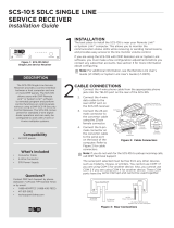
DB25 Connector Pinout
The figure below shows the pin connections of the ETHER-COM DB25 connector. Unlabeled pins are not connected.
Figure C-1: Pinout of Serial Port
25
1
14
13
RX (in) CTS (in)
TX (out) RTS (out) DSR (in)
Ground
DTR (out)
CD (in)
Note: The ETHER-COM DB25 connectors are male. Pinouts for
female DB25 connectors are the opposite of this pinout.
APPENDIX B - TROUBLESHOOTING
APPENDIX C - PINOUTS

Page 16
2841 E. Industrial Drive Springfield, MO 65802-6310 800-641-4282
ETHER-COM Installation/User’s Guide
Modem Wiring
DSR (Data Signal Ready) versus CD (Carrier Detect)
By default, most modems assert CD only during a valid connection. In this case the modem’s CD pin may be wired to the
ETHER-COM’s DSR pin. Alternately, many modems can be configured such that DSR acts like CD. In this case, the modem’s
DSR pin may be wired to the ETHER-COM’s DSR pin. Wiring the modem as described may permit the use of pre-assembled
connectors.
DTR (Data Terminal Ready)
The ETHER-COM normally asserts DTR. When modem control is enabled, the server will de-assert DTR for three seconds
each time the port is logged out and each time a user disconnects from a modem service. The modem must be configured to
hang up and recycle when DTR is de-asserted. If the modem is not configured in this way, sessions may not be properly
disconnected.
Specifications
This appendix lists the power requirements, temperature requirements, altitude limitations, and relative humidity limitations
of the ETHER-COM.
Power Specifications
The ETHER-COM is supplied with a power cube adaptor.
Adapter input voltage: 110 VAC (domestic)
220 VAC (international)
Adapter output voltage: 6 VDC
Operating current: 700mA at 6 Volts
Power consumption: 15 Watts (maximum)
Temperature Limitations
Operating range: 5½ to 50½C (41½ to 122½ F)
Storage range: -40½ to 66½C (-40½ to 151½F)
Maximum temperature
change per hour: 20½C (36½F)
Rapid temperature changes may affect operation. Do not operate the ETHER-COM near heating or cooling
devices, large windows, or doors that open to the outside.
Altitude Limitations
Operating: 2.4 km (8,000 ft)
Storage: 9.1 km (30,000 ft)
If you are operating the ETHER-COM above 2.4 km (8,000 ft), decrease the operating temperature rating by 1.8½C for each
1,000 m (1½F for each 1,000 ft).
Relative Humidity Limitations
Operating range: 10% to 90% (non-condensing) (40% to 60% recommended)
Storage range: 10% to 90% (non-condensing)
APPENDIX D - SPECIFICATIONS
APPENDIX C - PINOUTS

Page 17
2841 E. Industrial Drive Springfield, MO 65802-6310 800-641-4282
ETHER-COM Installation/User’s
Guide
Configuration for use with a DMP 462N or SCS-1 Receiver
This configuration is designed for applications where the Ether-Com server is used as the interface between the DMP SCS-
1 Receiver and an ethernet network and/or the 462N Network Interface Card on an XR200 panel and an ethernet network.
XR200/462N
Connect the ETHER-COM to a terminal configured for 9600 baud, 8 bits, no parity. Connect the ETHER-COM to an
Ethernet network. Apply power to the unit. If the unit passes its power-up diagnostics and completes the boot procedure, the
username> prompt should be displayed.
Enter your name and press the Return key. Become the privileged user. See chapter 4.
Enter the following commands at the Local>> prompt:
1. CHANGE IPADDRESS xxx.xxx.xxx.xxx (where xxx... is the IP address for the unit. Note: This address must be
unique to the network).
2. CHANGE GATEWAY xxx.xxx.xxx.xxx (where xxx... is the IP address for the Gateway or router attached to this LAN
segment).
3. CHANGE BOOTP DISABLED
4. CHANGE RARP DISABLED
5. CHANGE SPEED xxx (where xxx is the baud rate configured on the 462N (300 to 9600 baud)).
6. CHANGE FLOW CONTROL NONE
7. CHANGE DEDICATED TCP xxx.xxx.xxx.xxx:2001U (where xxx... is the IP address of the ETHER-COM connected
to the SCS-1 Receiver).
8. CHANGE AUTOSTART ENABLED
9. SHOW SERVER - Check and confirm the unit IP address and Gateway address. The unit is now ready to be con-
nected to the 462N with the cable provided with the ETHER-COM.
10. SHOW PORT - Check and confirm the speed, flow control, dedicated service, and autostart options are set correctly.
11. LOGOUT
Important Note
Once the ETHER-COM has been configured in this manner, no local access is allowed through the serial port while the unit
is connected to the network. To reconfigure the Ether-Com you must remove power from the unit, disconnect it from the
network, and then reapply power. Press the Enter key within 10 seconds to enter the configuration mode. Enter the command
FLUSH NVR to return the unit to its factory defaults. This erases all options including the IP address.
SCS-1 Receiver
The unit that connects to the SCS-1 Receiver is configured in the same manner with the exception of Dedicated Service.
The CHANGE DEDICATED option will not include any IP address, CHANGE DEDICATED TCP :2001U. This is necessary
because the unit connected to the receiver will need to communicate with many different IP addresses.
APPENDIX E - CONFIGURATION

Page 18
2841 E. Industrial Drive Springfield, MO 65802-6310 800-641-4282
ETHER-COM Installation/User’s Guide
Configuration for use with Remote Access+™ on a PC
This configuration is for applications where the Ether-Com server is used as the ethernet network interface for an IBM
compatible PC on which is installed the DMP Remote Access™ software. The Remote Access program is used as a monitoring
automation system and should be configured for HST Monitoring to allow it to process incoming alarm and system information
from DMP panels installed on the same network.
HST Monitoring
Connect the ETHER-COM to a terminal, or a PC running a terminal communication program, configured for 9600 baud, 8
bits, no parity. Connect the ETHER-COM to an Ethernet network. Apply power to the unit. If the unit passes its power-up
diagnostics and completes the boot procedure, the username> prompt should be displayed.
Enter your name and press the Return key. Become the privileged user. See chapter 4.
Enter the following commands at the Local>> prompt:
1. CHANGE IPADDRESS xxx.xxx.xxx.xxx (where xxx... is the IP address for the unit. Note: This address must be
unique to the network).
2. CHANGE GATEWAY xxx.xxx.xxx.xxx (where xxx... is the IP address for the Gateway or router attached to this LAN
segment).
3. CHANGE BOOTP DISABLED
4. CHANGE RARP DISABLED
5. CHANGE SPEED 9600
6. CHANGE FLOW CONTROL NONE
7. CHANGE DEDICATED TCP: 200IU
8. CHANGE AUTOSTART ENABLED
9. SHOW SERVER - Check and confirm the unit IP address and Gateway address. The unit is now ready to be con-
nected to the PC with a standard serial cable.
10. SHOW PORT - Check and confirm the speed, flow control, dedicated service, and autostart options are set correctly.
11. LOGOUT
Important Note
Once the ETHER-COM has been configured in this manner, no local access is allowed through the serial port while the unit
is connected to the network. To reconfigure the Ether-Com you must remove power from the unit, disconnect it from the
network, and then reapply power. Press the Enter key within 10 seconds to enter the configuration mode. Enter the command
FLUSH NVR to return the unit to its factory defaults. This erases all options including the IP address.
APPENDIX F - CONFIGURATION

Page 19
2841 E. Industrial Drive Springfield, MO 65802-6310 800-641-4282
ETHER-COM Installation/User’s
Guide
Configuration for use with Remote Access+™ on a PC continued
This configuration allows you to connect to DMP panels sharing a common ethernet network for programming and diagnostic
purposes.
Ether-Com™ Programming
Connect the ETHER-COM to a terminal, or a PC running a terminal communication program, configured for 9600 baud, 8
bits, no parity. Connect the ETHER-COM to an Ethernet network. Apply power to the unit. If the unit passes its power-up
diagnostics and completes the boot procedure, the username> prompt should be displayed.
Enter your name and press the Return key. Become the privileged user. See chapter 4.
Enter the following commands at the Local>> prompt:
1. CHANGE IPADDRESS xxx.xxx.xxx.xxx (where xxx... is the IP address for the unit. Note: This address must be
unique to the network).
2. CHANGE GATEWAY xxx.xxx.xxx.xxx (where xxx... is the IP address for the Gateway or router attached to this LAN
segment).
3. CHANGE BOOTP DISABLED
4. CHANGE RARP DISABLED
5. CHANGE SPEED 9600
6. CHANGE FLOW CONTROL NONE
7. CHANGE VERIFY ENABLED
8. CHANGE LOCAL SWITCH }
9. SHOW SERVER - Check and confirm the unit IP address and Gateway address. The unit is now ready to be con-
nected to the PC with a standard serial cable. You must power the unit up without being connected to the network so
the boot prompt will be displayed. Enter the command FLUSH NVR to return the unit to its factory defaults.
Note: This erases all options including the IP address.
10. SHOW PORT - Check and confirm the speed, flow control, dedicated service, and autostart options are set correctly.
11. LOGOUT
Important Note
Once the ETHER-COM has been configured in this manner, no local access is allowed through the serial port while the unit
is connected to the network. To reconfigure the Ether-Com you must remove power from the unit, disconnect it from the
network, and then reapply power. Press the Enter key within 10 seconds to enter the configuration mode. Enter the command
FLUSH NVR to return the unit to its factory defaults. This erases all options including the IP address.
APPENDIX F - CONFIGURATION

A
Altitude limitations ............................ D-2
ARP entry ..................................................
Autobaud ..............................................11
Autostart ...............................................12
B
Baud rate............................................... 11
Boot commands ................................. B-5
Boot prompt..........................................15
Boot troubleshooting ......................... B-2
BOOTP 2-5, 3-2, B-3, B-6
C
Cable, 10BASE-T ............................... 2-4
CD (Carrier Detect) ........................... C-2
Character size ..................................... 4-5
Circuit timer........................................ 4-4
Command set ...................................... 3-6
Configuration
IPX/SPX ...................................... 4-3
LAT 4-4
TCP/IP 4-3
D
DB25 connector......................... 2-1, C-1
Dedicated service................................ 4-7
Displaying current settings ................ B-7
Domain name server........................... 4-3
DSRLogout......................................... 4-6
DTRWait ............................................. 4-6
E
Encapsulation ..................................... 4-3
Error messages................................... B-5
Ether-Com™ Programming .................19
Ethernet address ................................ B-6
Ethernet, connecting to....................... 2-4
Example hardware layout................... 2-3
EZCon 1-4, 2-6
F
Factory defaults ................................. B-7
Flash ROM........................ 1-4, 2-5, B-3
Flow control........................................ 4-6
Flush NVR......................................... B-7
Frame type ..................................1-3, 4-3
G
Gateway4-4
Digital Monitoring Products
2841 E. Industrial Drive Springfield, MO 65802-6310 800-641-4282
H
Hardware address .............................. B-6
Hardware flow control........................ 4-6
Hardware layout example................... 2-3
Host 1-2
Humidity limitations.......................... D-2
HST Monitoring ...................................18
I
Inactivity logout.................................. 4-7
Inactivity timer ................................... 4-7
Internal network number .................... 4-3
Internal Routing.................................. 4-3
IP address......................... 2-6, B-1, B-6
IP Security .......................................... 4-4
IPX (NetWare) ............................1-3, 1-4
IPX/SPX Configuration...................... 4-3
L
LAT 3-5, 4-4
LAT identification............................... 4-4
LEDs 2-2, 2-4, 2-5
Loadfile B-4, B-7
Loadhost .................................... 4-4, B-6
Local prompt ............ 1-2, 3-4, 3-8, B-3
Logouts
General 3-8
Inactivity...................................... 4-7
M
Modem wiring ................................... C-2
Modem control ................................... 4-6
N
Name resolution ................................. 4-3
NetWare1-3, 1-4, 3-4, 4-3
Fileserver .................................... B-6
Node 1-2
NVRAM ............................................ B-7
O
OK LED.....................................2-5, B-2
P
Parity 4-5
Passwords ........................................... 4-1
Ping 2-6, 3-2
Pinouts C-1
Port 7000 ............................................ 3-7
Power specifications .......................... D-1
Power, supplying ....................... 2-1, 2-4
Power-up diagnostics.......................... 2-5
Power-up troubleshooting ................. B-2
Preferred service................................. 4-7
Prompts
Boot 3-6, B-5
Local 1-2, 3-4, B-3
R
RARP 2-5, 3-2, B-3, B-6
Rebooting the ETHER-COM ............ B-6
Remote console port ...................3-1, 3-7
Reset button ........................................ 2-1
RJ45 Ethernet connector .................... 2-1
Rlogin 1-4, 3-5
RTS/CTS............................................. 4-6
S
Serial connector .................................. 2-1
Serial console port .............................. 3-6
Serial device, connecting.................... 2-3
Serial port parameters.................2-4, 4-5
Service 1-2
Service groups .................................... 4-4
Services, preferred & dedicated ......... 4-7
Session 1-2
Set Privileged command ..................... 4-2
Signal checking .................................. 4-6
SNMP 1-3
Software loadfile name...................... B-7
Specifications..................................... D-1
Subnet mask ....................................... 4-3
Superuser privileges ...................3-2, 4-2
T
TCP/IP 4-3, B-1
Technical support............................... A-1
Telnet 1-4
Temperature limitations..................... D-2
TFTP B-4
Troubleshooting
Boot B-2
Error messages ........................... B-5
Power-up .................................... B-2
W
Warranty information ............................. v
Wiring, modem .................................. C-2
/