Page is loading ...

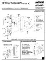
Top Retainer
Latchbolt
Mullio
n
Bottom
retainer
Set screw for
stabilizing mullion
located inside
retainer
Set screw for
stabilizing
the mullion
Dim. “x”
Retainer
Center
line of
latchbolt
Installation Instructions
L980S Lockable Non Fire Rated Mullion
1-800-727-5477 • www.sargentlock.com
A7687C 1/23
Copyright © 2008, 2023, SARGENT Manufacturing Company. All rights reserved. Reproduction in whole or in part without the express
written permission ofSARGENT Manufacturing Company is prohibited. Patent pending and/or patent www.assaabloydss.com/patents.
Pictures shown are for illustration purpose only. Actual product may vary.
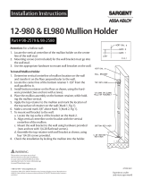
1Install exit devices according to instructions included with the
exit devices before installing mullion. This will ensure the correct
positioning of the mullion between the center cases.
2Center bottom retainer between doors and fasten in place with
screws provided.
3Center top retainer between doors and fasten in place with
screws provided.
4Determine the length of the mullion and cut off the bottom end.
5Place mullion assembly into bottom retainer and slide top of the
mullion into the top retainer until it latches.
(Length of Mullion = dim “x” -3/4”) (1/8” clearance at top)
6To eliminate any rattle remove mullion using the key and adjust set screws in top and bottom retainers.
Do not over tighten set screws.
7Position strike on center line of latch bolt per exit instructions, drill and tap mullion.
8Attach strike with (2) screws through slotted holes. Adjust for proper postion
and tighten screws. Drill and tap the (2) center holes in mullion and install
screws securely (both sides).
Top Retainer
Mullion
Latchbolt
Bottom Retainer
Set screw for
stabilizing
mullion
located inside
retainer

SARGENT
L
ocking arm
Locking
screw
Mullion
latchbolt
Cylinder with
blocking ring
Key way
A7687C 1/23
Copyright © 2008, 2023, SARGENT Manufacturing Company. All rights reserved. Reproduction in whole or in part without the express
written permission ofSARGENT Manufacturing Company is prohibited. Patent pending and/or patent www.assaabloydss.com/patents.
WARNING
This product can expose you to lead
which is known to the state of California
to cause cancer and birth defects or other
reproductive harm. For more information go
to www.P65warnings.ca.gov.
1
Cylinder Installation
Depress latchbolt and hold fully depressed while screwing cylinder into chassis until it bottoms out.
2Unscrew until keyway is at the bottom and the name on the cylinder is straight.
3Tighten locking screw so that the end of the locking arm mates with slot in the cylinder and tighten securely.
Keyway
Cylinder with blocking ring
Mullion latchbolt
Locking Screw
Locking Arm
/


