Bradley LD-5010 Installation guide
- Category
- Sanitary ware
- Type
- Installation guide
This manual is also suitable for

Installation
P.O. Box 309
Menomonee Falls, WI 53052 USA
800 BRADLEY (800 272 3539)
+1 262 251 6000
bradleycorp.com
215-1869 Rev. B; ECN 17-11-004B
© 2017 Bradley
Page 1 of 28 8/24/2017
LD-5010
OmniDeck
™
with WashBar
™
- 5000 Series
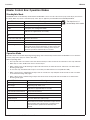
Table of Contents
Pre-Installation Information ................................................2
Supplies Required .............................................................2
Components ...................................................................3-4
Dimensions ...................................................................5-10
Structural Rough-Ins ........................................................11
Plumbing and Electrical Rough-Ins .................................12
Drain Assembly ...............................................................13
WashBar Installation ........................................................13
Aerator Installation ...........................................................14
Attach Soap Motor and Soap Container Bracket ............14
Bowl Mounting .................................................................15
Install P-Trap ....................................................................15
Strainer and Drain Cap ....................................................15
Dryer Motor Assembly ..................................................... 16
Attach Power Line Filter ..................................................17
Control Box and Valve Installation ...................................18
Soap Installation ..............................................................19
Electrical Connections ..................................................... 20
Adjust Temperature with Water Running .........................20
Access Panel ................................................................... 21
Master Control Box .....................................................22-26
Cleaning and Maintenance ......................................... 27-28

LD-5010 Installation
2 8/24/2017 Bradley • 215-1869 Rev. B; ECN 17-11-004B
WARNING
Make sure that all water supply lines have been flushed and then completely turned off before beginning
installation. Debris in supply lines can cause valves to malfunction.
Turn OFF electrical power to the electrical outlets, then unplug all electrical units prior to installation. Electrical
power MUST remain off until installation is complete.
Installer's hardware must be appropriate for wall construction. Wall anchors must have a minimum pull-out
rating of 1,000 pounds.
IMPORTANT
Read this entire installation manual to ensure proper installation. When finished with the installation, file this
manual with the owner or maintenance department. Compliance and conformity to local codes and ordinances
is the responsibility of the installer. Product warranties may be found under “Products” on our Web site at
www.bradleycorp.com.
Separate parts from packaging and make sure all parts are accounted for before discarding any packaging
material. If any parts are missing, do not begin installation until you obtain the missing parts.
For standard height mounting, do not exceed the recommended 33.5" distance from the fixture rim to the
finished floor.
Supplies Required
• 3/8" fasteners and wall anchors for wall bracket (minimum pull-out rating of 1,000 lbs.)
• (4) #10 fasteners and wall anchors for soap tank brackets (minimum pull-out rating of 100 lbs.)
• (4) #10 fasteners and wall anchors for access panel brackets (minimum pull-out rating of 100 lbs.)
• 1/2" hot/cold or tempered stub-out
• 1-1/2" NPT drain stub-out(s)
• (1) 110 volt GFCI protected electrical outlet per bowl (installed per local code).
• (1) Grounding Wire per bowl
• Drill
• Basin Wrench
• Tape Measure
• Phillips Screw Driver
• Flat Head Screw Driver
• Level
• 5/16" nut driver
• 5/16" socket (with or without extension)
• Construction adhesive suitable for solid surface, forming a strong permanent bond.

Installation LD-5010
Bradley • 215-1869 Rev. B; ECN 17-11-004B 8/24/2017 3
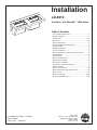
Components
WB-TR1 bowl
Chrome P-trap (S29-094)
Plastic P-trap (269-1697)
Access Panel
(186-1916)
DC Power
Adapter (2x)
(261-147)
Drain Cap
(111-142)
Drain Cap Spacer
(269-2540)
Trough Strainer
(173-041)
Trough Strainer Screw
(160-353)
O-Ring
(125-111)
Drain
Adapter
Packing
Washer
#10-24
Screw
Drain
Adapter
Prepack
(S45-2480)
Master Control Box
(S39-845)
#10 x 3/8" Screw (2x)
(P18-054)
Access Panel Bracket
(140-1172)
#10 Access Panel
Thumb Screw
(160-536)
Access Panel Security
Screw Option
(S45-2880)
Right-Hand Mounting Bracket with
Mounting Strip (S45-2452RH)
Left-hand Mounting Bracket with
Mounting Strip (S45-2452LH)
DC Lead Free Valve
Assembly, Single TMA
(S08-2401TMA)
DC Lead Free Valve
Assembly, Single TL
(S08-2401TL)

LD-5010 Installation
4 8/24/2017 Bradley • 215-1869 Rev. B; ECN 17-11-004B
Components
Control Box Assembly with
Liquid Pump (S52-166)
Control Box Assembly with
Foam Pump (S52-167)
Gallon Jug
(Supplied by Others)
Soap Tank Bracket
(140-1171)
Hose Clamps - 2-1/2" Dia
(269-678)
Flexible PVC
(269-2561A)
Dryer Motor
(S39-844)
Dryer Vibration Pad
4" x 10"
(124-105)
(Not Shown)
Hook and Loop Strap
(269-2574)
Hook and Loop Strap
(not shown)
(269-2574)
Liquid Pump with External
Rubber Sleeve Connection
(269-2518)
Foam Pump with Internal
Press Fit Connection
(269-2519)
Casting ASM. WashBar,
Chrome w/ LED
(S05-214F01)
Union Tube, 1/4" OD
(269-624)
1/4" x 60 Tubing (269-547C)
For Service - 1' Increments (R68-600011)
Elbow, 1/4 x 3.4mm
Hose Barb (145-221)
Gasket WashBar
Deck, Soap Side
(124-101)
Soap Tube
5.5mm OD x 55cm long
(269-2522)
Access Plate ASM,
Soap with Sensor
Printed Circuit Board
(S04-121)
Aerator .50 GPM (S05-175)
Aerator .35 GPM (S05-215)
(Aerators are shipped loose
in bag with red service key)
Nut, WashBar, 1-3/8-18
(110-256)
Washer Ground .25"
QC (230-035)
Gasket, WashBar Deck,
Air Side (124-102)
Screw #4-40 x 1/2 Pan
Mach SS (160-418)
Screw, #4-40 x 1/4 Pan
Mach SS Black Oxide
(160-534)
Access Plate ASM,
Air/Water with Sensor
Printed Cricuit Board
(S04-122)
Union Elbow
(269-2531)
Nut, WashBar,
1-3/8-18
(110-256)

Installation LD-5010
Bradley • 215-1869 Rev. B; ECN 17-11-004B 8/24/2017 5
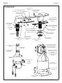
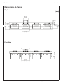
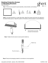
Dimensions - 1-Person
Top View
Front View
(mm)
30"
(762)
20-1/2"
(521)
5"
(127)
11-1/2"
(292)
13-1/2"
(343)
3-1/8"
(79)
11"
(279)
10-3/4"
(273)
5"
(127)
19-1/8"
(485)
22-1/2"
(571)
5"
(127)
21-5/8"
(549)

LD-5010 Installation
6 8/24/2017 Bradley • 215-1869 Rev. B; ECN 17-11-004B
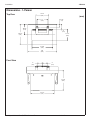
Dimensions - 2-Person
Top View
Front View
(mm)
60"
(1524)
20-1/2"
(521)
11-1/2"
(292)
10-3/4"
(273)
5"
(127)
13-1/2"
(343)
3-1/8"
(79)
11"
(279)
19-1/5"
(485)
5"
(127)
5"
(127)
22-1/2"
(571)
21-5/8"
(549)

Installation LD-5010
Bradley • 215-1869 Rev. B; ECN 17-11-004B 8/24/2017 7
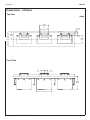
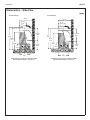
Dimensions - 3-Person
Top View
Front View
(mm)
20-1/2"
(521)
11-1/2"
(292)
10-3/4"
(273)
5"
(127)
13-1/2"
(343)
3-1/8"
(79)
19-1/5"
(485)
5"
(127)
5"
(127)
22-1/2"
(571)
11"
(279)

LD-5010 Installation
8 8/24/2017 Bradley • 215-1869 Rev. B; ECN 17-11-004B
Dimensions - 4-Person
Top View
Front View
(mm)
20-1/2"
(521)
11-1/2"
(292)
10-3/4"
(273)
5"
(127)
13-1/2"
(343)
3-1/8"
(79)
19-1/5"
(485)
5"
(127)
5"
(127)
22-1/2"
(571)
11"
(279)
21-5/8"
(549)

Installation LD-5010
Bradley • 215-1869 Rev. B; ECN 17-11-004B 8/24/2017 9
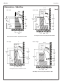
Dimensions – Side View
(mm)
Standard Height
Juvenile Height
Deck depth must be 20-1/2" minimum for ADA,
Enhanced Reach depth is only 20-1/2".
Deck depth must be 20-1/2" minimum for ADA,
Enhanced Reach depth is only 20-1/2"
20-1/2"
(521)
8"
(203)
34"
(864)
33-1/2"
(851)
27"
(686)
9"
(229)
17"
(432)
14-5/16"
(363)
19-3/16"
(488)
10-7/8"
(275)
20-1/2"
(521)
8"
(203)
31"
(787)
30-1/2"
(775)
9"
(229)
17"
(432)
11-5/16"
(363)
19-3/16"
(488)
24"
(610)
10-7/8"
(275)

LD-5010 Installation
10 8/24/2017 Bradley • 215-1869 Rev. B; ECN 17-11-004B
OBC Height
BCBC Height
CSA Height
Quebec Height
Deck depth must be 20-3/4" (527) minimum for OBC
Deck depth must be 22-1/2" (565) minimum for BCBC
Deck depth must be 21" minimum for CSA
Deck depth must be 23-1/2" (597) minimum for QBC
Dimensions – Side View
(mm)
20-3/4"
(527)
8-1/16"
(205)
33-1/16"
(787)
28-15/16"
(735)
13-3/4"
(350)
16-15/16"
(432)
13-7/8"
(352)
19-3/16"
(488)
27"
(685)
11-13/16"
(300)
11-1/8"
(282)
22-1/2"
(565)
9-13/16"
(250)
34-1/16"
(865)
28-15/16"
(735)
27"
(685)
9-13/16"
(250)
19-11/16"
(500)
14-7/8"
(378)
19-3/16"
(488)
7-7/8"
(200)
12-5/8"
(320)
21"
(533)
7-7/8"
(200)
33-7/8"
(860)
29-15/16"
(760)
28-3/8"
(720)
9-1/16"
(230)
16-15/16"
(430)
14-11/16"
(372)
19-3/16"
(488)
7-7/8"
(200)
11-3/8"
(288)
23-1/2"
(597)
11"
(280)
34-1/16"
(865)
26-15/16"
(685)
9-1/16"
(230)
16-15/16"
(430)
14-7/8"
(377)
19-3/16"
(488)
7-7/8"
(200)
13-7/8"
(352)

Installation LD-5010
Bradley • 215-1869 Rev. B; ECN 17-11-004B 8/24/2017 11
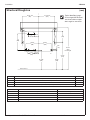
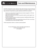
Structural Rough-Ins
(mm)
CODE DESCRIPTION QTY.
A 3/8" wall anchors with a minimum pull-out force of 1,000 lbs. per local codes 2 per bracket
C
Install wall anchor with a minimum pull-out force of 100 lbs. per local codes at locations shown
4
S #10 Wall Anchors for Soap Control Box Bracket 4
S1 #10 Wall Anchors for Soap Tank Bracket (100 lb pull out force) 4
13-1/4" min
(337)
13-1/4" min
(337)
9"
(229)
33-1/2"
(851)
Deck Height
21-3/4"
(552)
15-5/8"
(396)
3/4"
(19)
15-9/16"
(394)
10-3/8"
(264)
3-1/4"
(83)
5-1/2"
(140)
13"
(330)
10-3/8"
(264)
5"
(127)
3-1/2"
(89)
A
A
S S
C
C
S1
S1
A
A
C
C
C
L
Typical OmniDeck rough-
ins for single WB-TR1 bowl
are shown. Other multiple-
bowl rough-ins are similar.
Finished Floor
RIM HEIGHT VERTICAL HEIGHT ADJUSTMENTS FIXTURE STYLE
34" No Adjustment Standard Height, ADA, TAS
31 Subtract 3" Juvenile, ADA and TAS
33-1/16" Subtract 15/16" OBC
34-1/16" Add 1/16" BCBC and QBC
33-7/8" Subtract 1/8" CSA

LD-5010 Installation
12 8/24/2017 Bradley • 215-1869 Rev. B; ECN 17-11-004B
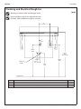
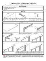
Plumbing and Electrical Rough-Ins
Mounting for Standard, ADA and TAS height shown.
(mm)
CODE DESCRIPTION QTY.
A 1½" NPT Drain, Stub-out 2" from wall 1
H,C
½" Nominal (⁵⁄₈" O.D. Comp.) Hot/Cold supplies, Stub-out 2" from wall
1
E 110V GFI protected electrical outlet (15 amp circuit breaker) 1
C
L
9"
(229)
33-1/2"
(851)
Deck Height
23-3/4"
(603)
E
17-1/2"
(444)
2-1/4"
(57)
1"
(25)
H
C
23-3/4"
(603)
W
1"
(25)
Finished Floor
Typical OmniDeck rough-ins for single WB-TR1 bowl
are shown. Other multiple-bowl rough-ins are similar.
Tempered
Supply

Installation LD-5010
Bradley • 215-1869 Rev. B; ECN 17-11-004B 8/24/2017 13
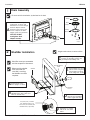
For ease of drain installation, lay the bowl on its back.
1
Drain Assembly
O-Ring
Drain
Adapter
Packing
Washer
#10-24
Screw
Assemble the remaining
components as shown and
thread the four screws through
the drain adapter and into
the basin inserts. Ensure the
screws compress the drain
adapter evenly onto the basin.
A
WashBar Installation
2
Single station shown; 2 station similar.
Assemble WashBar through basin
WashBar holes. Run cables and
tubes on left side only.
B
Secure from underside
with nuts and grounding
washer (right side only).
D
WashBar
Grounding Washer,
.25 QC
Nut, WashBar,
1-3/8-18
Connect grounding wire (supplied by
installer) to grounding washer and
ground per local building code.
C
Position bowl on the
floor, upright, as shown.
A
Soap Tube (Clear), 1/4" Water
Tube, LED Cable (Gray), Soap
Sensor Cable (Shorter Cable) and
Air/Water Cable (Longer Cable)
WashBar comes pre-assembled,
with the exception of the aerator.
Attach flexible PVC dryer
tube to shank using hose
clamp. Tighten to 30-35
in. lbs using 5/16" socket.
E
Attach the 1/4" supply
tube to the 1/4" union
elbow.
F
When attaching flexible
PVC dryer tube, be
sure tube is touching
the WashBar nut when
complete.
NOTICE! Do NOT
overtighten drain
adapter screws.

LD-5010 Installation
14 8/24/2017 Bradley • 215-1869 Rev. B; ECN 17-11-004B
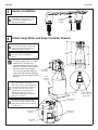
Aerator Installation
3
Red Service Key
Aerator
(0.35 gpm or
0.5 gpm)
Carefully thread the aerator into
the WashBar casting using the red
service key provided. Ensure no
leaks after installation.
A
Attach Soap Motor and Soap Container Bracket
4
Attach soap motor control box and
soap container bracket to wall using
#10 fasteners at locations shown in
Structural Rough-In drawing.
A
Install the soap pump onto gallon
container opening (supplied by
others).
B
The liquid soap pump has a rubber
sleeve that fits over the soap
container opening. The foam soap
pump has an interior white cylinder
that fits into the soap container.
This fit up may be tight. Move the
soap pump laterally while applying
pressure to seat into soap container
opening.
Soap Motor
Control Box
Soap
Container
Bracket
To check soap fitup, slide gallon jug
with soap pump into soap motor
control box. Ensure soap pump flange
is positioned below motor control box
lever and soap control box flange
is positioned in soap pump groove.
Gallon jug should rest on soap
container bracket without soap pump
pulling off of container.
C
Soap Pump
Flange
Motor Control
Box Lever
Once fitup is correct, remove soap
container with pump attached and set
aside. Soap container will be installed
in a later step.
D
Soap Control
Box Flange
Soap Pump
Groove
15-1/2"
(394)
13"
(330)
6-5/8"
(168)
12"
(305)
Liquid soap pump
shown. Foam soap
pump similar.
Soap Supply
Tube

Installation LD-5010
Bradley • 215-1869 Rev. B; ECN 17-11-004B 8/24/2017 15
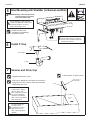
Bowl Mounting with WashBar (to Bracket and Wall)
5
Apply PC-Concrete® injectable repair
and anchoring epoxy (or equal) to
the top of the mounting strips (left-
hand bracket shown).
B
WARNING Backing substrate required for
structural integrity if brackets
aren't secured to a stud.
1 station shown, 2 station similar.
Strainer and Drain Cap
7
Position drain cap over
trough strainer, aligning
tabs into drain. Push
drain cap down until drain
cap is flush with basin.
Grommets should hold
drain cap securely against
drain trough walls.
A
To remove drain cap,
carefully slip flat
screwdriver into left or
right hand corner of
drain cap and gently lift
upwards.
B
WashBar removed for clarity.
Front
Note Angle of
Drain Cap
Drain cap is labeled front and back. Be sure front is
facing the user. Top surface of drain cap should be
sloped away from user.
Install P-Trap
6
Drain Adapter
P-Trap
Secure brackets to wall using 3/8"
fasteners (supplied by installer). See
Structural Rough-Ins section for
bracket mounting locations.
A
Bracket locations and
quantities vary depending
on the deck layout.

LD-5010 Installation
16 8/24/2017 Bradley • 215-1869 Rev. B; ECN 17-11-004B
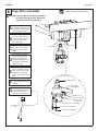
Dryer Motor Assembly
8
Slide the hose clamp onto
the flexible PVC dryer tube
and begin to tighten clamp
so that it does not fall off.
A
Dryer Outlet Nozzle
Dryer Motor
Foam Bumper
Dryer Motor Feet
Power Cord to GFCI Outlet
Dryer Motor, 120V/60Hz
Power Cord to DC Adapter
After assembly, dryer
motor should hang freely.
Secure dryer motor foam
bumper to finished wall,
in-line with the dryer motor
feet.
E
Discard water detector
wire (shipped loose) and
RJ45 connector cable
from motor and discard.
G
Bundle loose cords to
motor using hook and loop
cable tie.
F
Flexible Hose
Hose Clamp
Front View of Motor
CAUTION If dryer motor is not secured properly
to flexible PVC dryer tube, motor may
come lose and detach from tube.
While holding the motor
from the bottom with one
hand, insert dryer outlet
nozzle into the flexible
PVC dryer tube.
B
Tighten hose clamp using
the 5/16" socket wrench.
Tighten clamp to 30-35
in/lbs.
C
Check to be sure motor
is securely attached to
flexible PVC dryer tube
by gently pulling down on
motor. Motor should stay
attached to tube.
D
RJ45 Connector Cable
(unplug from motor
and discard)
1 station shown, 2 station similar.
Water Detector
Wire

Installation LD-5010
Bradley • 215-1869 Rev. B; ECN 17-11-004B 8/24/2017 17
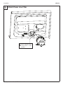
Attach Power Line Filter
9
Secure dryer power line
filter to underside of bowl
using (2) #10 x 1" screws
provided.
A

LD-5010 Installation
18 8/24/2017 Bradley • 215-1869 Rev. B; ECN 17-11-004B
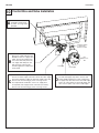
Control Box and Valve Installation
10
Secure control box to
underside of bowl using
(2) #10 x 1/2" long screws
provided.
A
1/4" Water Supply
Outlet with
Compression Nut
Cold Supply
Hot Supply
Cold
Hot
Attach 1/4" supply tube from the
WashBar to the 1/4" supply valve
outlet. Loosen the compression
nut on the valve body. Push the
1/4" supply tube firmly into the
tube connector until it is fully
seated. Tighten the compression
nut by hand.
B
For thermostatic mixing valve installation, secure 1/2" supply
hose to hot water supply valve inlet. Secure the other supply
hose from cold water supply to cold water supply valve inlet.
Secure valve to bowl using (2) #10 x 1/2" long screws.
For tempered line installation, secure 1/2" supply hose
to tempered water supply and TL valve inlet (not shown).
Secure valve to bowl using (2) #10 x 1/2" long screws.
C
3/8"
Compression
Nut
Remove 3/8" compression nut/sleeve from the
hot and cold supply stop valves. Connect 3/8"
end of flexible supply hose to 3/8" compression
on supply stop valve. Ensure hot and cold supply
hoses are connected to hot and cold supply stop
valve. For TL option, only connect cold supply.
D

Installation LD-5010
Bradley • 215-1869 Rev. B; ECN 17-11-004B 8/24/2017 19
Soap Installation
11
The soap system is designed to be used with a standard
U.S. gallon soap container. For accurate low soap
indication, user needs to set soap type (see configuration
mode at the end of this manual on how to set soap type.
Attach soap supply tube from the
WashBar to the top of the soap pump.
A
To manually prime the soap, press
down on the control box lever arm 6
to 8 times.
G
Use the hook and loop strap provided
to secure container to soap bracket.
Feed end of cable tie (smooth side
facing you) through the right side slot
of bracket flange at top. Feed through
left side flange slot and wrap around
jug. Secure with hook and loop end.
D
Ensure that the soap tube is not
kinked. Position hand above soap
motor control box and adjust tube if
needed.
F
Slide gallon jug with soap pump into
soap motor control box. Ensure soap
pump flange is positioned below motor
control box lever and soap control
box flange is positioned in soap pump
groove. Gallon jug should rest on soap
container bracket without soap pump
pulling off of container.
C
Attach soap pump with supply tubes
attached into gallon jug.
B
For ease of soap container
removal, pull tank while rotating
bottom of tank out.
Ensure Soap Pump
Flange is Positioned
Below Control Box Lever
Attach Soap Supply Tube Here
Top Flange
Cable Tie Slot
Soap Container
Bracket
Hook and Loop Strap
Soap Pump
Soap cycle count defaults to liquid soap configuration. If
you have the foam soap option, please see Setting the
Soap Type under Configuration Mode towards the end of
this manual.
Control Box
Flange
Soap Pump
Groove

LD-5010 Installation
20 8/24/2017 Bradley • 215-1869 Rev. B; ECN 17-11-004B
Electrical Connections
12
Air/Water Sensor
Board Connector
(Red) - From
WashBar (Shorter
of 2 Sensor
Cables - Red)
Soap Sensor
Board Connector
- From WashBar
(Longer of 2
Sensor Cables)
LED Board
Connector - From
WashBar
(Gray Cable)
Not Used
Connector Plug
to DC Valve Plug
Female Barrel
Plug to Soap
Motor Control Box
Male Barrel Plug
Connector Plug to
Dryer Motor
(Gray Cable)
Make (3) connections from
the WashBar assembly as
shown (Air/Water Sensor,
Soap Sensor and LED)
A
Make barrel plug and
connector plug connections
as shown.
C
USB for Software
Upgrades
Each WashBar requires the same connections.
After all connections are made,
reference Master Control Box:
System Startup section later in
this manual.
D
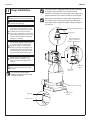
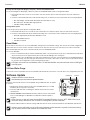
Adjust Temperature with Water Running
H
C
A
Loosen Cap Screw about 1/4" (4-6
turns) and lift up cover (do not
remove).
B
Using cover, turn cartridge gently until
desired water temperature is reached.
Do not turn past stops as this may
damage unit. Push cover down and
tighten screw.
WARNING This valve is NOT factory
preset. Upon installation,
the temperature of this
valve must be checked and
adjusted to ensure delivery
of a safe water temperature.
Water in excess of 110°F
(43°C) may cause scalding.
13
Connect DC power adapter male barrel
plug into master control female barrel
plug. Plug the DC power adapter into
the blower power cord.
B
This End to
Master Control
Box Female Barrel
Plug
DC Power
Adapter
Dryer
Power Cord
Page is loading ...
Page is loading ...
Page is loading ...
Page is loading ...
Page is loading ...
Page is loading ...
Page is loading ...
Page is loading ...
-
 1
1
-
 2
2
-
 3
3
-
 4
4
-
 5
5
-
 6
6
-
 7
7
-
 8
8
-
 9
9
-
 10
10
-
 11
11
-
 12
12
-
 13
13
-
 14
14
-
 15
15
-
 16
16
-
 17
17
-
 18
18
-
 19
19
-
 20
20
-
 21
21
-
 22
22
-
 23
23
-
 24
24
-
 25
25
-
 26
26
-
 27
27
-
 28
28


Bradley LD-5010 Installation guide
- Category
- Sanitary ware
- Type
- Installation guide
- This manual is also suitable for
Ask a question and I''ll find the answer in the document
Finding information in a document is now easier with AI
Related papers
-
Bradley Express Crescent CRS-2/IR/LSD Installation guide
-
-
-
-
-
Bradley Express SS-3N Installation guide
-
-
-
Bradley S53-325 Installation guide
-
Other documents
-
 Ghent DPSC2429-GA Installation guide
-
Blue Sea Systems 1007100 Operating instructions
-
3M Scotch-Brite™ Roloc™ Clean and Strip XT Pro Extra Cut Disc User guide
-
 Flow Wall FSS-MB2412-2S User guide
-
 Urbanest 1200406 Installation guide
-
Alpine 425-WHI-2PK User manual
-
Bartscher 850007 Operating instructions
-
Alpine Industries 426-GRY-2PK Installation guide
-
HQ W3-65021-HQN Datasheet
-
 Stern Classic Automatic Soap Dispenser Installation guide


