Installation SS-3N
Bradley • 215-1493 Rev. K; ECN 17-08-010 5/18/2017 13
Cleaning and Maintenance for Terreon
®
(Bowl and Cover)
Material Description: Terreon is a densified solid surface material composed of bio based resin and is resistant to chemicals,
stains, burns and impact. Surface can be easily repaired with everyday cleansers or fine grit abrasives. Because Terreon is a
unique cast material, its aggregate flow and distribution, and shades of color can vary from product to product creating natural
characteristics.
Routine Cleaning: For regular cleaning, use mild neutral base cleaners.
Stubborn Stains: Remove tough stains with Soft-Scrub
®
and a green Scotch-Brite
®
pad or lightly sand in a circular motion with
240 grit wet/dry sandpaper. The finish can then be renewed with a maroon Scotch-Brite pad.
Scratches: Remove scratches with a green Scotch-Brite pad. The finish can then be renewed with a maroon Scotch-Brite pad.
Hard Water Deposits: Remove hard water deposits with a mild solution of vinegar and water. Always rinse the unit thoroughly
after cleaning.
Restoring the surface:
Use Hope’s
®
Perfect Countertop to refresh and protect the Terreon Solid Surface material. Dark Terreon
colors may require additional care and maintenance. For complete instructions on this additional maintenance, visit bradleycorp.com.
Repair Kits: Terreon repair kits are available. Contact your Bradley representative or distributor for part numbers and pricing.
Repair kits are made to order and have a shelf life of 30 days.
NOTICE! Do not use strong acid or alkaline chemicals and cleaners to clean Terreon. If these chemicals
come in contact with the surface, wipe them off immediately and rinse with soapy water. Avoid
contact with harsh chemicals such as paint remover, bleach, acetone, etc. Avoid contact with hot
pans and objects.
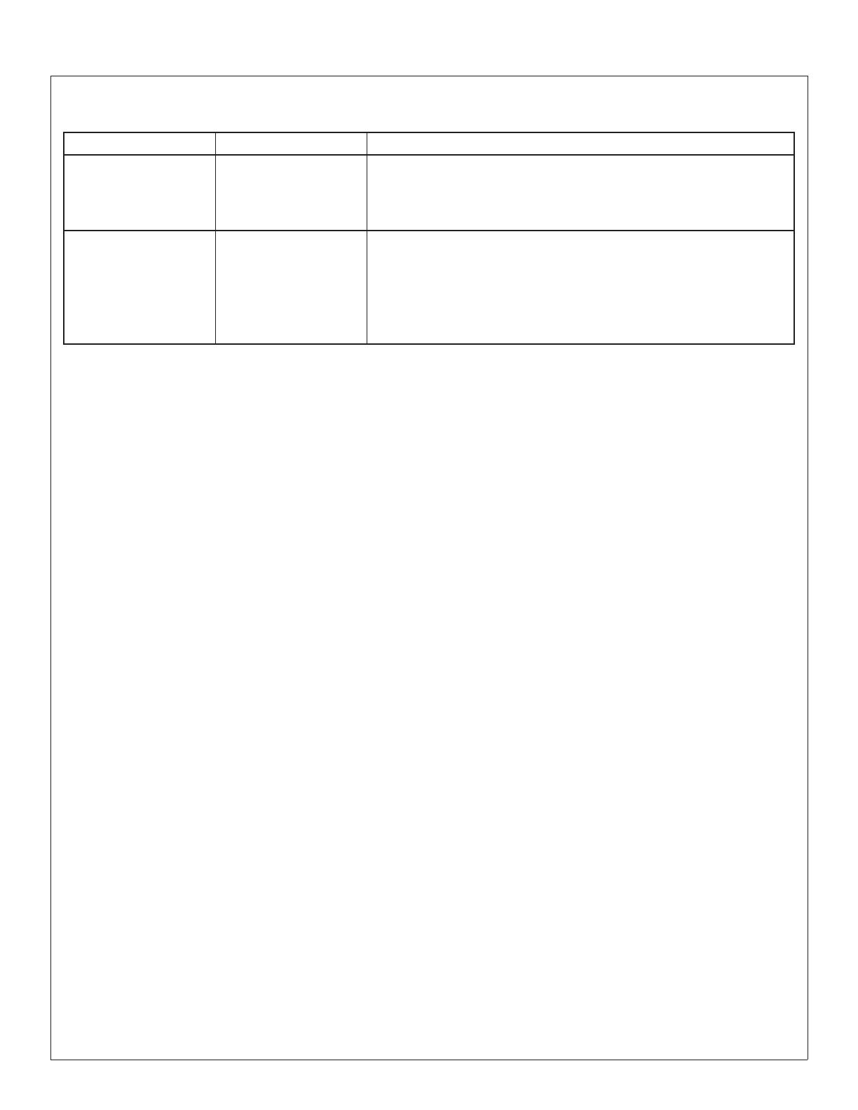
Stop Valve Troubleshooting
Problem Cause Solution
Water dribbles or
does not flow from the
sprayhead.
Stop Valves may not be
functioning properly.
1. Close the stops and inspect the valves that supply water to the
lavatory system.
2. Inspect the stop valves to see that they have been properly
installed.
Sprayhead delivers
ONLY hot OR cold water.
Stop Valves may not be
functioning properly.
1. Close the stops and inspect the valves that supply water to the
lavatory system.
2. Inspect the stop valves to see that they have been properly
installed.
3. Inspect the thermostatic mixing valve for proper installation and
connection to hot and cold supplies.
Brand Names
Use of brand names is intended only to indicate a type of cleaner. This does not constitute an endorsement, nor does the
omission of any brand name cleaner imply inadequacy. Many products named are regional in distribution, and can be found in
local supermarkets, department and hardware stores, or through your cleaning service. It is emphasized that all products should
be used in strict accordance with package instructions.


