Page is loading ...

© UPLIFT Desk • 800-349-3839 • [email protected] • upliftdesk.com 1
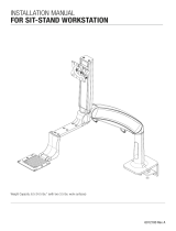
Package Contents
Eneld Dual Monitor Arm
SKU: MON042
Package Contents
Allen Wrenches
(set of two: 4mm, 6mm)
Lower Arm
(qty 2)
Wire Cover
Upper Arm
(qty 2)
Lower Clamp
VESA Plate
(qty 2)
Upper Clamp
M5x12 Screw (M-B) (qty 8)
M5 Washer (M-C) (qty 8)
M4x12 Screw (M-A) (qty 8)
M6x12 Flathead Screw (qty 3)
Flat Wrench
Base
Lower arm
Upper arm
Vesa mount (x1)
Lower base plate
Upper base plate
Bar Handle
Adhesive Pad
Wire Cover
Upper Clamp
Lower Clamp
Base screw (x4)
3mm Allen wrench
L
4mm Allen wrench
M
6mm Allen wrench
N
D5 Washers (x4)
M5x12 bolt (x4)
M4x12 bolt (x4)
O Bolt (x4)
N Bolt (x4)
Base
Lower arm
Upper arm
Vesa mount (x1)
Lower base plate
Upper base plate
Bar Handle
Adhesive Pad
Wire Cover
Upper Clamp
Lower Clamp
Base screw (x4)
3mm Allen wrench
L
4mm Allen wrench
M
6mm Allen wrench
N
D5 Washers (x4)
M5x12 bolt (x4)
M4x12 bolt (x4)
O Bolt (x4)
N Bolt (x4)
Base
Lower arm
Upper arm
Vesa mount (x1)
Lower base plate
Upper base plate
Bar Handle
Adhesive Pad
Wire Cover
Upper Clamp
Lower Clamp
Base screw (x4)
3mm Allen wrench
L
4mm Allen wrench
M
6mm Allen wrench
N
D5 Washers (x4)
M5x12 bolt (x4)
M4x12 bolt (x4)
O Bolt (x4)
N Bolt (x4)
Base
Lower arm
Upper arm
Vesa mount (x1)
Lower base plate
Upper base plate
Bar Handle
Adhesive Pad
Wire Cover
Upper Clamp
Lower Clamp
Base screw (x4)
3mm Allen wrench
L
4mm Allen wrench
M
6mm Allen wrench
N
D5 Washers (x4)
M5x12 bolt (x4)
M4x12 bolt (x4)
O Bolt (x4)
N Bolt (x4)
Base
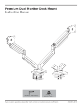
Clamp Method Bolt-Through Method
• Acceptable monitor weight range: 4.4 lb to 19.8 lb (per monitor)
• Recommended monitor size: up to 32” (measured diagonally)
• Desktop thickness compatibility:
• Clamp Method: 0.4”-3.3” thick.
• Bolt-through Method: 0.4”-3.1” thick
There are two ways to attach the Eneld Dual Monitor Arm to your desktop. If you would like to attach it along the back
edge of your desktop, follow the Clamp Method instructions starting on this page. If you prefer to attach it through your
desktop, follow the Bolt-Through Method instructions starting on page 2.
Step 1
Determine your mounting method. There are two
ways to attach the Eneld Dual Monitor Arm to your
desktop:
Clamp Method: If you would like to attach the monitor
arm along the back edge of your desktop, follow the
Clamp Method instructions (Steps 2 - 4).
Bolt-Through Method: If you prefer to attach the
monitor arm through your desktop, skip Steps 2 - 4
and follow the Bolt-Through Method instructions
(Steps 5 - 7).
Step 2 (Clamp Method)
Align the Upper Clamp with the Base in the orienta-
tion shown and attach it using the three M6x12 Flat-
head Screws and the 4mm Allen Wrench.
Clamp Method
Parts for
Bolt-through assembly
Upper Base Plate
Lower Base Plate
Long Bolt
M8 Washer
M8 Nut

© UPLIFT Desk • 800-349-3839 • [email protected] • upliftdesk.com
2
g. 2g. 1
Step 5 (Bolt-Through Method)
Ensure the desktop has a hole between 0.4’’ and 3.1’’
in diameter to use this option.
Using a grommet hole that is already in your desktop
is acceptable, or you can drill a 0.5” diameter hole
anywhere on your desktop.
Bolt-Through Method
Step 3 (Clamp Method)
A. There are two sets of holes in the Upper Clamp to
use for different desktop thicknesses.
• There are two screws pre-installed in the top
two holes of the Upper Clamp. Leave the screws
in those holes if your desktop is between 0.4’’
and 2.1’’ thick (g. 1)
• If your desktop is between 2’’ and 3.3’’ thick, use
the 4mm Allen Wrench to remove the screws
from the top two holes and insert them into the
bottom two holes (g. 2)
B. Use the 4mm Allen Wrench to adjust the two
screws in the Upper Clamp so that there is about
0.25” of thread between the plate and screw
heads.
C. Position the Lower Clamp assembly in the orienta-
tion shown and press it against the Upper Clamp
so the two screws go through the two key slot
holes in the Lower Clamp.
D. Slide the Lower Clamp assembly down so that
the screws are at the top of the key slot holes and
tighten the screws with 4mm Allen Wrench.
Step 4 (Clamp Method)
A. Using the knob screw, adjust the bolt on the bot-
tom of the Lower Clamp so that the opening is
wide enough to accommodate the thickness of
the desktop.
B. Slide the assembly onto the back of the desktop,
then tighten the knob screw to secure the Base to
the desktop.
Step 6 (Bolt-Through Method)
A. From the top of the Upper Base Plate (the side
opposite from the countersunk holes), insert the
Long Bolt through the square hole until the square
shank of the Bolt ts into the Plate’s square hole.
B.
Align the Upper Base Plate with the bottom of the base
in the orientation shown and attach it using the three
M6x12 Flathead Screws and the 4mm Allen Wrench.
0.25”
0.25”
0.25”
0.25”
0.25”
0.25”
0.25”
0.25”
0.4”
3.1”

© UPLIFT Desk • 800-349-3839 • [email protected] • upliftdesk.com 3
Arm Assembly & Monitor Mounting
Step 7 (Bolt-Through Method)
A. Lower the Base assembly to the desktop guiding
the Long Bolt through the hole in the desktop.
B. Slide the Lower Base Plate onto the Long Bolt and
secure it against the desktop with the M8 Washer
and Nut.
C. Tighten the Nut with the Flat Wrench while ensur-
ing the Lower Base Plate straddles the hole.
D. Proceed with the Arm Assembly & Monitor Mount-
ing, Step 8.
Step 8
A. The Base comes with a pre-installed limiting screw
in each of the posts which limit the rotation of each
arm to 180 degrees.
If you want to limit the rota-
tion of the arms to 180 degrees, leave these screws
installed and use the 4mm Allen Wrench to ensure
they are tight (be careful not to overtighten).
B. If you want the arms to rotate a full 360 degrees,
remove the screws with the 4mm Allen Wrench.
•
We recommend saving these screws in case you
decide to limit the rotation of the arms in the future.
Step 9
Slide each of the Lower Arms onto the posts of the
Base until they are fully seated and tighten the set
screws at the back of each Lower Arm with the at-
head end of the 4mm Allen Wrench (or a small at
head screwdriver). This will secure the Lower Arms to
the Base and keep them from becoming separated
during adjustment.

© UPLIFT Desk • 800-349-3839 • [email protected] • upliftdesk.com
4
Step 11
Reminder: The acceptable monitor weight range for
each of the Eneld Dual Monitor Arms is 4.4 lb to 19.8
lb per arm.
A. Lay your monitor face down on a clean surface or
a towel to prevent damage to your screen.
B. Test the M4x12 and M5x12 Screws in your moni-
tor’s screw holes to determine which is the right
size for your monitor.
C. Line up the holes of the VESA Plate with the holes
on your monitor, orienting the VESA Plate as
shown, with the VESA Plate’s knob pointing to-
ward the top of the monitor.
D. Attach the VESA Plate to the monitor using the
selected screws with the M5 Washers.
E. Repeat with the second monitor.
top
Step 10
Warning, Pinch Point: Pay attention! When handling
the Upper Arms, keep hands and ngers clear of the
Upper Arm’s pivot location when moving, installing,
and making adjustments to the Eneld Monitor Arm.
A. Slide the post of each of the Upper Arms into the
hole at the top end of each of the Lower Arms un-
til they are fully seated.
B. Tighten the set screws on the front of each of the
Lower Arms with the at-head end of the provid-
ed 4mm Allen Wrench (or a small at head screw-
driver). This will prevent the Upper Arms from
becoming separated from the Lower Arms during
adjustment.
Step 12
A. Make sure the knob on the VESA Plate is in the
“Unlock” position, perpendicular to the monitor.
B. Slide the VESA Plate into the slot shown in the Up-
per Arm.
C. Once the VESA Plate is inserted all the way into
the Upper Arm, turn the knob on the VESA Plate
to the “Lock” position, parallel to the monitor.
D. Pull up slightly on your monitor to make sure it is
locked securely in place.
E. Repeat with the second monitor.

© UPLIFT Desk • 800-349-3839 • [email protected] • upliftdesk.com 5
Step 13
A. Move a monitor to any position and release it. If
the monitor does not drift up or down, the arm is
properly counterbalanced.
B. If the monitor does not remain where you po-
sitioned it, you will need to adjust the tension of
the spring to properly support the weight of your
monitor using the 6mm Allen Wrench on the ten-
sion adjustment screw (located at the back end
of the Upper Arm). View how much the spring is
tensioned via the tension indicator on top of the
Upper Arm.
Caution: To prevent damage to the tension indicator,
never adjust the counterbalance screw so that the red
indicator line moves past the “+” or “-” symbols.
•
If the monitor drifted down, hold the Upper Arm
in a horizontal position and use the 6mm Allen
Wrench to turn the adjustment screw so that the
tension indicator moves toward the “+” symbol
until the monitor remains in place when you let go.
• If the monitor drifted upward, turn the adjust-
ment screw so that the tension indicator moves
towards the “-” symbol until the monitor remains
in place when you let go.
C. Repeat with the second monitor arm.
Step 14
A. You can rotate the monitors to be in either portrait
or landscape orientation.
B. If the monitor does not hold in place when rotat-
ed, tighten the screws shown with a Phillips Head
screwdriver to keep the monitor in position.
C. Repeat with the second monitor.
If the arm drops,
If the arm rises,
If the arm drops,
If the arm rises,
If the arm drops,
If the arm rises,
If the arm drops,
If the arm rises,
Step 15
A. To adjust the front and back tilt of your monitor,
loosen the socket head screw on the side of the
Upper Arm where shown with the 4mm Allen
Wrench.
B. Once the monitor is at your preferred viewing an-
gle, re-tighten the screw with the Allen Wrench to
hold the monitor in place.
C. Repeat with the second monitor.

© UPLIFT Desk • 800-349-3839 • [email protected] • upliftdesk.com
6
Step 16
A. To use the arm’s wire management, rst remove
the built-in wire covers.
B. There are two wire covers on each arm, one lo-
cated under the Upper Arm and the other under
the Lower Arm. They are removed by gripping the
sides of the cover and sliding it forward (toward
the monitor) to unlock and remove. Be careful not
to pull down on the cover, doing so may damage
the covers.
C. Run your cables up and under each section of the
monitor arm and replace the covers the opposite
way that they were removed.
Step 17
A. If you have selected the Clamp Method, you can
now snap the Wire Cover onto the back of the Up-
per Clamp on the Base as shown and insert your
monitor cables through the integrated clips.
B. In addition to holding the cables in place, there are
convenient holes to store the Allen Wrenches for
future adjustment needs.
C. The Wire Cover adds 0.75” to the back of the mon-
itor arm. If your desk is close to a wall or cubicle,
or has a privacy panel attached to the back of the
desktop, there may not be enough space available
to attach the Wire Cover.

© UPLIFT Desk • 800-349-3839 • [email protected] • upliftdesk.com 7
Monitor Tilt
Each Monitor can tilt at the VESA mount forward or
backward within a range of 80° (+/-40°).
Height Adjustment
The center of the VESA mount can go as high as 18.5”
and as low as 8.7’’ from the desktop.
8.7”
18.5”
Monitor Swivel
Each Monitor can swivel 180° (+/-90°) at the hinge at
the top of the Upper Arm.
Monitor Rotation
Each Monitor can rotate at the VESA mount 360°
allowing landscape or portrait viewing.
Upper Arm Swivel
Each Upper Arm can swivel 180° (+/-90°).
Lower Arm Swivel
Each Lower Arm can swivel a full 360°, depending on
monitor size, monitor orientation, and the location of
the other arm.
Each Lower Arm can also be set to allow only a range
of 180° (See Step 8 in the “Arm Assembly & Monitor
Mounting” section for adjustment details.)
We do not recommend swiveling the Monitors past
the back of the desk as this may cause instability.
Adjustment Information

© UPLIFT Desk • 800-349-3839 • [email protected] • upliftdesk.com
8
Copyright Notice: These instructions are a component of this accessory. These instructions are part of the scope of delivery, even if the item is resold. These instructions are also available on the UPLIFT Desk website: uplift-
desk.com. Excerpts or copies may not be forwarded to third parties or used in any other published form without the prior written consent of UPLIFT Desk. These instructions are subject to United States copyright law.
©
CAUTION: Read all instructions before assembly. Failure to assemble or operate properly may
result in damage or personal injury. Retain manual for future reference.
CAUTION: Max monitor weight is 19.8 lbs per arm. Using a monitor over 19.8 lbs could result in
instability causing possible injury.
CAUTION: Do not overtighten screws. Overtightening may cause damage to your equipment.
CAUTION: Leave enough slack in the cables to allow the monitor arms to move freely.
WARNING: Ensure the desktop is strong enough to support the combined weight of the moni-
tor arms and attached equipment.
WARNING: Pinch point: Keep ngers clear of Upper Arm’s hinge when installing and making
adjustments.
WARNING:
The arms will be in tension and will spring up quickly when attached equipment is re-
moved. Do not remove equipment unless the arms have rst been raised to their highest position.
CAUTION: Do not use on hollow core tables or desktops.
CAUTIONS & WARNINGS
!
!
!
!
!
!
!
!
!
AI-MON042-1.1
/