Page is loading ...

www.ScanGauge.com
SGDQS101
5) Learn How to Save Fuel With ScanGauge
The easiest way to learn to improve your fuel economy is to have real-time feedback about
how your driving style effects overall fuel use. ScanGauge can provide both Miles Per Gallon
(MPG) as well as Average Fuel Economy (AVG) in real-time to help you adjust your driving
style to reach maximum fuel economy.
Start Learning to Save Fuel!
With your gauges set, your ScanGauge is now ready to provide real-time feedback about your
fuel usage as you drive. This will allow you to see what adjustments in your driving style can
be made to actually raise or lower your Average Fuel Economy (AVG).
Your goal is to bring up your AVG
reading as high as possible. To do this,
try and adjust your driving style so that
your Miles Per Gallon (MPG) reading is
equal to or higher than your AVG. You
can also use the Gallons/Liters Per
Hour (GPH/LPH) to gauge how much fuel your vehicle will use each hour of driving. The Trip
Fuel Cost (TFC) gauge will show you the total cost of the fuel used. You can think of the TFC
gauge as a taxi meter.
Using these real-time gauges, you can experiment with different driving styles, or even different
driving routes, to reduce your fuel cost.
Set Your Gauges
Use the function buttons next to each gauge
position to select the following gauges:
AVG Average Fuel Economy
MPG Mile Per Gallon
GPH/LPH Gallons/Liters Per Hour
TFC Trip Fuel Cost
Push the function buttons to
cycle through the available Digital Gauges.
<SCAN
<TRIP
GAUGE>
MORE>
20.5AVG 1.2GPH
9.20TFC25.2MPG
Home Screen
20.5AVG 1.2GPH
9.20TFC25.2MPG
20.5AVG 1.2GPH
9.20TFC25.2MPG
Quick Start Guide
Plugs into the J1939 or J1708 diagnostic connector already
built into most 1987 or Newer Diesel Pusher Motor Homes,
RV’s and Large Diesel Over-The-Road Trucks
3) Fuel Level and Cost Adjustments
The FILLUP function allows you adjust and
enter the fuel level and cost values to help
ScanGauge maintain accurate TO EMPTY
and FUEL COST computations.
Initial Setup
To set the tank level initially, access the
FILLUP screen and use the upper left and
right function buttons to adjust the “TANK=”
value to what you estimate is in the tank.
Using the FILLUP Screen
Use the FILLUP screen each time you put
fuel in the tank. Adjust the number shown
in the top line using the upper left and right
function buttons until the number matches
the amount of fuel you put in the tank.
You can increase the number in 10 gallon/
liter steps and decrease in 1 gallon/liter
steps.
If you’re tank is full, press the function
button next to “+10” until the “TANK=” value
is the same as the tank capacity.
Fuel Cost Screen
When you’re done adjusting the fuel,
press the NEXT button to access the Fuel
Cost Screen. Use the upper left and right
function buttons to adjust the fuel cost, then
press SAVE.
4) Using Your ScanGauge
Your ScanGauge features an easy-
to-use menu-driven design. Pushing
the button next to each selection will
display that information. Pushing the
HOME button will take you back to the
Home Screen at anytime.
<SCAN
<TRIP
GAUGE>
MORE>
Push the HOME button to return to
the Home Screen at anytime.
GAUGE
Use the built-in Digital Gauges
The function buttons next to each gauge allow you
to select and display up to 4 gauges at a time.
1937RPM
16.2MPG
55MPH
3.40GPH
Push the function buttons to cycle through
the available digital gauges.
SCAN
Turn off the Check Engine Lamp
When you vehicle’s computer detects a
problem, it may store a trouble code. The
ScanGauge gives you the ability to read and
clear these trouble codes. ScanGauge will
provide a Code ID and Failure Mode for
each saved trouble code.
Visit ScanGauge.com for an explanation of
known trouble codes.
TRIP
Using the Trip Computers
ScanGauge stores up to 4 sets of trip data and the Performance Monitor. For instructions
on using the Performance Monitor, please refer to the ScanGauge User Manual.
Push to cycle through the available Trip Computers.
Push to cycle through the available trip data.
Displays the data stored for the currently selected Trip Computer
The currently selected Trip Computer
< >
<CURRENT RESET>
65 MPH MAX
Push the function button next to CLEAR to clear the code
Selected Code
Code ID Failure mode
Number of Occurrences
1 STORED CODES
<CODES CLEAR>
ID
110
FM
11
#
<1
CNT
01>
•If you fill up your fuel tank with your ve-
hicle on an incline, it can have an effect
on the amount of fuel the pump can dis-
pense into your tank.
•When filling your tank, let the pump shut
off automatically. Do not top off.
•To maintain the most accurate “TO EMP-
TY” information, it is best to fill the tank
to its capacity
Helpful Hints
<SCAN
<TRIP
GAUGE>
MORE>
<SETUP
<DISPLAY
MORE>
FILLUP>
0
NEXT>Tank= 85
<-1 +10>
Fuel Cost
<
SAVE>
>$4.10
Push the SAVE button to complete the FILLUP process
and reset the TRIP parameters related to fuel.
FILLUP Screen
Fuel Cost Screen

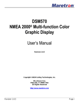
2) Set Up Your ScanGauge
Your new ScanGauge must first be set up so
that it may report accurate information about
your vehicle.
To access the Basic Setup Options, follow
the sequence shown to the right. For more
detailed setup instructions and a complete
explanation of each of the setup parameters,
please refer to the ScanGauge User Manual.
Use the lower buttons to adjust the
currently selected setup parameter
Use the upper buttons to move to the next or
previous setup parameter
Displays the currently selected setup parameter
Package Contents
• ScanGauge
• 6-ft J1939/J1708 Cable
• Velcro
®
Strips
• Quick Start Guide
Front
A. Function/Selection Button
B. Function/Selection Button
C. Function/Selection Button
D. Function/Selection Button
E. Home Button
F. LCD Display Screen
Back
G. J1939/J1708 Connection Plug
Side
H. Optional J1939/J1708 Connection
Plug or unit daisy chain interface
Front Side
Back
A
B
C
D
E
H
G
F
ScanGauge Layout
HOME Screen
<SCAN
<TRIP
GAUGE>
MORE>
<SETUP
<DISPLAY
MORE>
FILLUP>
< >
< >
DISTANCE
MILES
Setup Parameter Display Options
Distance Units DISTANCE Miles, Kilometers
Fuel Units FUEL UNITS Gallons, Liters
Temperature Units TEMP UNITS Fahrenheit(˚F),Celsius(˚C)
Pressure Units PRESSURE UNITS PSI, KPA, MM, IN
Tank Size TANK SIZE Adjustable in 1 Gallon/Liter Increments
Currency type CURRENCY
$, £, ¥,
元 ,€
Advanced Settings ADV SETTINGS For an explanation of the Advanced Setting Options,
please refer to the user manual and ScanGauge.com
5. Connect the small end of the cable
Plug the small end of the cable into the back or side of the
ScanGauge.
6. Turn the vehicle on.
Start your vehicle or turn the ignition to the ON position.
Plug the ScanGauge Plug Into The Diagnostic Connector.
While inserting in the plug, you may have to rotate to the plug to align the connector pins.
Once the pins are aligned, push firmly on the plug to complete the connection.
Once connected with the vehicle running or the ignition in the ON position, your ScanGauge
will display the Connecting Screen, and then quickly switch to the Home Screen.
When the Home Screen is displayed, your ScanGauge is connected and has established
communication with your vehicle’s computer.
Connecting...
<TRIP MORE>
Connecting Screen
<SCAN
<TRIP
GAUGE>
MORE>
Home Screen
Up to 10
seconds
7. Proceed to setup.
If it does not stop saying “Connecting...” or the screen goes blank after 60 seconds,
refer to Troubleshooting section in the ScanGauge User Manual.
Small end of the cable
connects to your ScanGauge.
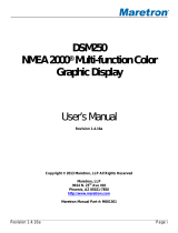
1) Quick Start Installation
1. Locate the Diagnostic Connector
The connector is generally located under
the dash at the fire wall on the driver
side and is usually protected by a plastic
cover. To remove the protective cover,
you must push the cover while turning
counter clockwise, then pull to remove it.
2. Determine Plug Type
The universal plug
included with your
ScanGauge is compatible
with both the J1939 (9pin)
and J1708 (6-pin)
diagnostic port. Match the
end of the plug to the
connector, but do not plug
it in at THIS time.
3. Locate a Place For The ScanGauge.
You can use the sticky-back Velcro
®
supplied with the ScanGauge to attach it to the
location you have chosen.
DO NOT mount the ScanGauge over an air bag cover where it could be
propelled by a deploying airbag.
4. Route The Cable.
Route the cable from the ScanGauge to your vehicle’s diagnostic connector. Be sure
Keep the cord from interfering with the pedals or operating controls of the vehicle.
6-pin connects to vehicles
that use the J1708 protocol
9-pin connects to vehicles
that use the J1939 protocol
Typical J1939/J1708 protective cover

2) Set Up Your ScanGauge
Your new ScanGauge must first be set up so
that it may report accurate information about
your vehicle.
To access the Basic Setup Options, follow
the sequence shown to the right. For more
detailed setup instructions and a complete
explanation of each of the setup parameters,
please refer to the ScanGauge User Manual.
Use the lower buttons to adjust the
currently selected setup parameter
Use the upper buttons to move to the next or
previous setup parameter
Displays the currently selected setup parameter
Package Contents
• ScanGauge
• 6-ft J1939/J1708 Cable
• Velcro
®
Strips
• Quick Start Guide
Front
A. Function/Selection Button
B. Function/Selection Button
C. Function/Selection Button
D. Function/Selection Button
E. Home Button
F. LCD Display Screen
Back
G. J1939/J1708 Connection Plug
Side
H. Optional J1939/J1708 Connection
Plug or unit daisy chain interface
Front Side
Back
A
B
C
D
E
H
G
F
ScanGauge Layout
HOME Screen
<SCAN
<TRIP
GAUGE>
MORE>
<SETUP
<DISPLAY
MORE>
FILLUP>
< >
< >
DISTANCE
MILES
Setup Parameter Display Options
Distance Units DISTANCE Miles, Kilometers
Fuel Units FUEL UNITS Gallons, Liters
Temperature Units TEMP UNITS Fahrenheit(˚F),Celsius(˚C)
Pressure Units PRESSURE UNITS PSI, KPA, MM, IN
Tank Size TANK SIZE Adjustable in 1 Gallon/Liter Increments
Currency type CURRENCY
$, £, ¥,
元 ,€
Advanced Settings ADV SETTINGS For an explanation of the Advanced Setting Options,
please refer to the user manual and ScanGauge.com
5. Connect the small end of the cable
Plug the small end of the cable into the back or side of the
ScanGauge.
6. Turn the vehicle on.
Start your vehicle or turn the ignition to the ON position.
Plug the ScanGauge Plug Into The Diagnostic Connector.
While inserting in the plug, you may have to rotate to the plug to align the connector pins.
Once the pins are aligned, push firmly on the plug to complete the connection.
Once connected with the vehicle running or the ignition in the ON position, your ScanGauge
will display the Connecting Screen, and then quickly switch to the Home Screen.
When the Home Screen is displayed, your ScanGauge is connected and has established
communication with your vehicle’s computer.
Connecting...
<TRIP MORE>
Connecting Screen
<SCAN
<TRIP
GAUGE>
MORE>
Home Screen
Up to 10
seconds
7. Proceed to setup.
If it does not stop saying “Connecting...” or the screen goes blank after 60 seconds,
refer to Troubleshooting section in the ScanGauge User Manual.
Small end of the cable
connects to your ScanGauge.
1) Quick Start Installation
1. Locate the Diagnostic Connector
The connector is generally located under
the dash at the fire wall on the driver
side and is usually protected by a plastic
cover. To remove the protective cover,
you must push the cover while turning
counter clockwise, then pull to remove it.
2. Determine Plug Type
The universal plug
included with your
ScanGauge is compatible
with both the J1939 (9pin)
and J1708 (6-pin)
diagnostic port. Match the
end of the plug to the
connector, but do not plug
it in at THIS time.
3. Locate a Place For The ScanGauge.
You can use the sticky-back Velcro
®
supplied with the ScanGauge to attach it to the
location you have chosen.
DO NOT mount the ScanGauge over an air bag cover where it could be
propelled by a deploying airbag.
4. Route The Cable.
Route the cable from the ScanGauge to your vehicle’s diagnostic connector. Be sure
Keep the cord from interfering with the pedals or operating controls of the vehicle.
6-pin connects to vehicles
that use the J1708 protocol
9-pin connects to vehicles
that use the J1939 protocol
Typical J1939/J1708 protective cover

www.ScanGauge.com
SGDQS101
5) Learn How to Save Fuel With ScanGauge
The easiest way to learn to improve your fuel economy is to have real-time feedback about
how your driving style effects overall fuel use. ScanGauge can provide both Miles Per Gallon
(MPG) as well as Average Fuel Economy (AVG) in real-time to help you adjust your driving
style to reach maximum fuel economy.
Start Learning to Save Fuel!
With your gauges set, your ScanGauge is now ready to provide real-time feedback about your
fuel usage as you drive. This will allow you to see what adjustments in your driving style can
be made to actually raise or lower your Average Fuel Economy (AVG).
Your goal is to bring up your AVG
reading as high as possible. To do this,
try and adjust your driving style so that
your Miles Per Gallon (MPG) reading is
equal to or higher than your AVG. You
can also use the Gallons/Liters Per
Hour (GPH/LPH) to gauge how much fuel your vehicle will use each hour of driving. The Trip
Fuel Cost (TFC) gauge will show you the total cost of the fuel used. You can think of the TFC
gauge as a taxi meter.
Using these real-time gauges, you can experiment with different driving styles, or even different
driving routes, to reduce your fuel cost.
Set Your Gauges
Use the function buttons next to each gauge
position to select the following gauges:
AVG Average Fuel Economy
MPG Mile Per Gallon
GPH/LPH Gallons/Liters Per Hour
TFC Trip Fuel Cost
Push the function buttons to
cycle through the available Digital Gauges.
<SCAN
<TRIP
GAUGE>
MORE>
20.5AVG 1.2GPH
9.20TFC25.2MPG
Home Screen
20.5AVG 1.2GPH
9.20TFC25.2MPG
20.5AVG 1.2GPH
9.20TFC25.2MPG
Quick Start Guide
Plugs into the J1939 or J1708 diagnostic connector already
built into most 1987 or Newer Diesel Pusher Motor Homes,
RV’s and Large Diesel Over-The-Road Trucks
3) Fuel Level and Cost Adjustments
The FILLUP function allows you adjust and
enter the fuel level and cost values to help
ScanGauge maintain accurate TO EMPTY
and FUEL COST computations.
Initial Setup
To set the tank level initially, access the
FILLUP screen and use the upper left and
right function buttons to adjust the “TANK=”
value to what you estimate is in the tank.
Using the FILLUP Screen
Use the FILLUP screen each time you put
fuel in the tank. Adjust the number shown
in the top line using the upper left and right
function buttons until the number matches
the amount of fuel you put in the tank.
You can increase the number in 10 gallon/
liter steps and decrease in 1 gallon/liter
steps.
If you’re tank is full, press the function
button next to “+10” until the “TANK=” value
is the same as the tank capacity.
Fuel Cost Screen
When you’re done adjusting the fuel,
press the NEXT button to access the Fuel
Cost Screen. Use the upper left and right
function buttons to adjust the fuel cost, then
press SAVE.
4) Using Your ScanGauge
Your ScanGauge features an easy-
to-use menu-driven design. Pushing
the button next to each selection will
display that information. Pushing the
HOME button will take you back to the
Home Screen at anytime.
<SCAN
<TRIP
GAUGE>
MORE>
Push the HOME button to return to
the Home Screen at anytime.
GAUGE
Use the built-in Digital Gauges
The function buttons next to each gauge allow you
to select and display up to 4 gauges at a time.
1937RPM
16.2MPG
55MPH
3.40GPH
Push the function buttons to cycle through
the available digital gauges.
SCAN
Turn off the Check Engine Lamp
When you vehicle’s computer detects a
problem, it may store a trouble code. The
ScanGauge gives you the ability to read and
clear these trouble codes. ScanGauge will
provide a Code ID and Failure Mode for
each saved trouble code.
Visit ScanGauge.com for an explanation of
known trouble codes.
TRIP
Using the Trip Computers
ScanGauge stores up to 4 sets of trip data and the Performance Monitor. For instructions
on using the Performance Monitor, please refer to the ScanGauge User Manual.
Push to cycle through the available Trip Computers.
Push to cycle through the available trip data.
Displays the data stored for the currently selected Trip Computer
The currently selected Trip Computer
< >
<CURRENT RESET>
65 MPH MAX
Push the function button next to CLEAR to clear the code
Selected Code
Code ID Failure mode
Number of Occurrences
1 STORED CODES
<CODES CLEAR>
ID
110
FM
11
#
<1
CNT
01>
•If you fill up your fuel tank with your ve-
hicle on an incline, it can have an effect
on the amount of fuel the pump can dis-
pense into your tank.
•When filling your tank, let the pump shut
off automatically. Do not top off.
•To maintain the most accurate “TO EMP-
TY” information, it is best to fill the tank
to its capacity
Helpful Hints
<SCAN
<TRIP
GAUGE>
MORE>
<SETUP
<DISPLAY
MORE>
FILLUP>
0
NEXT>Tank= 85
<-1 +10>
Fuel Cost
<
SAVE>
>$4.10
Push the SAVE button to complete the FILLUP process
and reset the TRIP parameters related to fuel.
FILLUP Screen
Fuel Cost Screen
/